

Tele Web Controller
Telecontrol Module through the WEB
USER MANUAL
grifo
®
ITALIAN TECHNOLOGY
http://www.grifo.it http://www.grifo.com
Tel. +39 051 892.052 (a. r.) FAX: +39 051 893.661
Tele Web Controller
, GPC®, grifo®, are trade marks of grifo
Via dell' Artigiano, 8/6
40016 San Giorgio di Piano
(Bologna) ITALY
E-mail: grifo@grifo.it
Rel. 5.00 Edition 27 October 2004
®

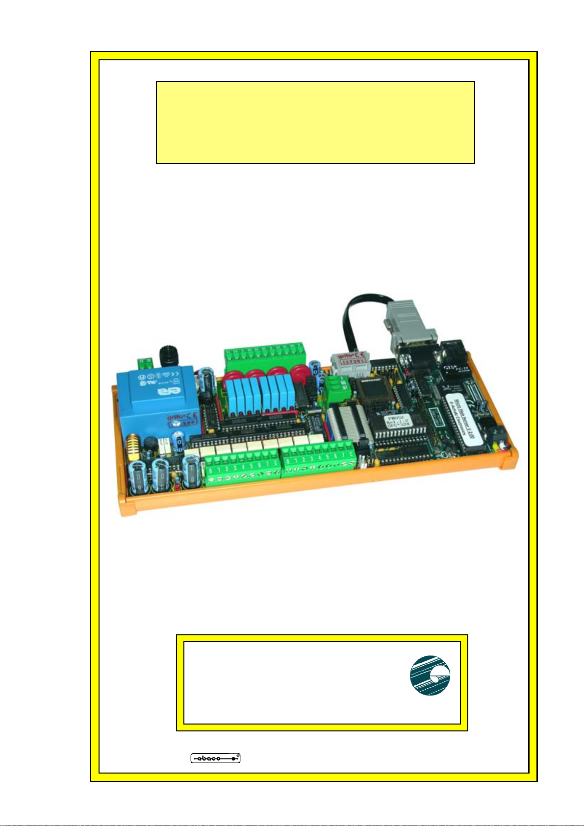
Tele Web Controller
Telecontrol Module through the WEB
USER MANUAL
Can be driven through Internet using a normal Web Browser (e. g.
Internet Explorer, Netscape, ecc.) from anywhere in the world.
Access to all the on-board resouces through Password protected Web
pages. Can manage up to 32 Optocoupled Inputs and 24 Outputs
buffered by transistor or relay, visualized by LEDs on board. Each
signal has its own identification Label, that the user can change via
Web. Signals status is reported by graphics on the Web page. Optional
Web page to manage a Real Time Clock backed with Lithium battery.
Optional Web page to manage a Data Logger that can save data in
Excel compatible format. Optional Web page to manage eventual
Black Outs date and time memorization (available only matched with
real time clock). Optional Web page to manage Analog Inputs.
Connection to internet thorugh on-board Ethernet interface. IP
address can be changed dynamilically, even when the server is
working. Wide range of power supply. Development system provided
with IDE. Powerful programming language PCode to optimize CGI
Scripts and control directly all the hardware interfaces and all the
protocols supported. Supported protocols: TCP/IP, BOOTP, SMTP,
HTTP, PING, UDP. Wide range of example programs. PicoWeb
development software can be used with Win95/98/Win2k and XP.
Complete documentation in PDF format that explains every detail
about instalaltion, development and finalization of application program.
grifo
®
ITALIAN TECHNOLOGY
http://www.grifo.it http://www.grifo.com
Tel. +39 051 892.052 (a. r.) FAX: +39 051 893.661
Tele Web Controller
, GPC®, grifo®, are trade marks of grifo
Via dell' Artigiano, 8/6
40016 San Giorgio di Piano
(Bologna) ITALY
E-mail: grifo@grifo.it
Rel. 5.00 Edition 27 October 2004
®
DOCUMENTATION COPYRIGHT BY grifo® , ALL RIGHTS RESER VED
No part of this document may be reproduced, transmitted, transcribed, stored in a
retrieval system, or translated into any language or computer language, in any form or
by any means, either electronic, mechanical, magnetic, optical, chemical, manual, or
otherwise, without the prior written consent of grifo
®
.
IMPORTANT
Although all the information contained herein have been carefully verified, grifo
assumes no responsability for errors that might appear in this document, or for damage
to things or persons resulting from technical errors, omission and improper use of this
manual and of the related software and hardware.
®
grifo
reserves the right to change the contents and form of this document, as well as
the features and specification of its products at any time, without prior notice, to obtain
always the best product.
For specific informations on the components mounted on the card, please refer to the
Data Book of the builder or second sources.
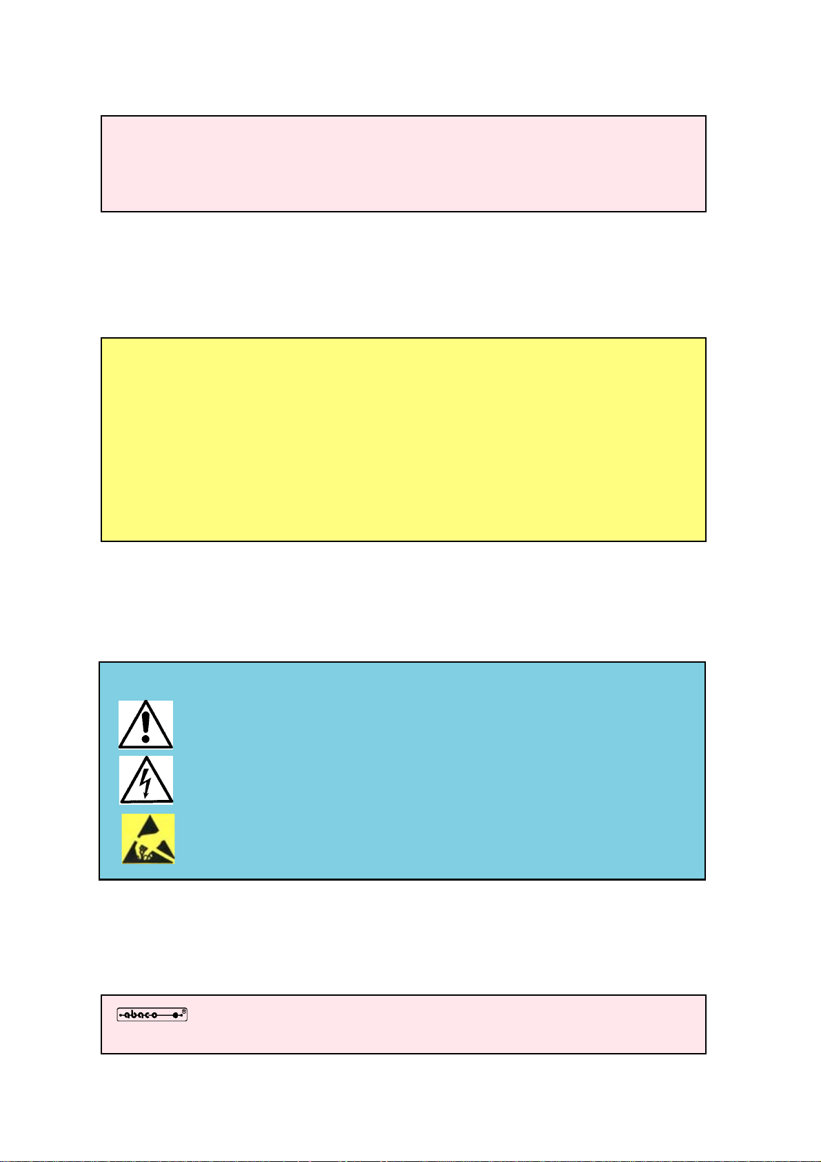
SYMBOLS DESCRIPTION
In the manual could appear the following symbols:
Attention: Generic danger
®
Attention: High voltage
Attention: ESD sensitive device
Trade Marks
, GPC®, grifo® : are trade marks of grifo®.
Other Product and Company names listed, are trade marks of their respective companies.
ITALIAN TECHNOLOGY grifo
®
GENERAL INDEX
INTRODUCTION ........................................................................................................................ 1
FIRMWARE VERSION .............................................................................................................. 3
GENERAL INFORMATION ...................................................................................................... 4
INTERNET INTERFACE ...................................................................................................... 6
OUTPUT SECTION OF ZBR ................................................................................................ 6
OUTPUT SECTION OF ZBT ................................................................................................ 6
INPUT SECTION OF ZBT AND ZBR .................................................................................. 6
POWER SUPPLY SECTION ................................................................................................. 6
TECHNICAL FEATURES .......................................................................................................... 8
GENERAL FEATURES .......................................................................................................... 8
PHYSICAL FEATURES......................................................................................................... 8
ELECTRIC FEATURES......................................................................................................... 9
INSTALLATION ........................................................................................................................ 10
MATERIAL REQUIRED ..................................................................................................... 10
POWER SUPPLY .................................................................................................................. 10
SOFTWARE INSTALLATION ............................................................................................ 12
LOW LEVEL CONFIGURATION...................................................................................... 12
ZBX MAPPING ADDRESS............................................................................................. 15
HIGH LEVEL CONFIGURATION..................................................................................... 16
UTILIZATION ........................................................................................................................... 17
LOGIN .................................................................................................................................... 17
OUTPUT COMMANDS ....................................................................................................... 18
INPUT COMMANDS............................................................................................................ 18
LABELS MANAGEMENT .................................................................................................. 20
REAL TIME CLOCK MANAGEMENT (OPTIONAL) ................................................... 20
DATA LOGGER MANAGEMENT (OPTIONAL) ............................................................ 20
ANALOG INPUTS MANAGEMENT (OPTIONAL) ........................................................ 22
PERSONALIZATIONS ............................................................................................................. 23
PERSONALIZATION OF ICONS....................................................................................... 24
PERSONALIZATION OF HTML PAGES ......................................................................... 24
APPENDIX A: ALPHABETICAL INDEX ............................................................................ A-1
GMB HR168 & GMM AC0 Rel. 3.00
Page I
grifo
®
ITALIAN TECHNOLOGY
FIGURE INDEX
FIGURE 1: BLOCKS DIAGRAM ............................................................................................................ 5
FIGURE 2: PHOTO OF TELE WEB ...................................................................................................... 7
FIGURE 3: SNAPSHOT OF MICRO WEB SERVER ............................................................................... 11
FIGURE 4: SNAPSHOT OF ZBR 168 ................................................................................................ 1 1
FIGURE 5: MICRO WEB SERVER COMPLETE DELIVERY.................................................................... 13
FIGURE 6: LOW LEVEL CONFIGURATION .......................................................................................... 14
FIGURE 7: ZBX MAPPING ADDRESS.................................................................................................. 15
FIGURE 8: SNAPSHOT OF A GPC® 324D......................................................................................... 15
FIGURE 9: LOGIN ........................................................................................................................... 17
FIGURE 10: COMMANDS PAGE OF ZBX 168..................................................................................... 19
FIGURE 11: LABELS MANAGEMENT ................................................................................................. 19
FIGURE 12: CHANGE SIGNALS NAMES.............................................................................................. 21
Page II
GMB HR168 & GMM AC0 Rel. 3.00
ITALIAN TECHNOLOGY grifo
®
INTRODUCTION
The use of these devices has turned - IN EXCLUSIVE WAY - to specialized personnel.
This device is not a safe component as defined in directive 98-37/CE.
Pins of Modules are not provided with any kind of ESD protection. They are connected directly to
their respective pins of microcontroller. Modules are affected by electrostatic discharges.
Personnel who handles Modules is invited to take all necessary precautions to avoid possible
damages caused by electrostatic discharges.
The purpose of this handbook is to give the necessary information to the cognizant and sure use of
the products. They are the result of a continual and systematic elaboration of data and technical tests
saved and validated from the manufacturer, related to the inside modes of certainty and quality of
the information.
The reported data are destined- IN EXCLUSIVE WAY- to specialized users, that can interact with
the devices in safety conditions for the persons, for the machine and for the enviroment, impersonating
an elementary diagnostic of breakdowns and of malfunction conditions by performing simple
functional verify operations , in the height respect of the actual safety and health norms.
The informations for the installation, the assemblage, the dismantlement, the handling, the adjustment,
the reparation and the contingent accessories, devices etc. installation are destined - and then
executable - always and in exclusive way from specialized warned and educated personnel, or
directly from the TECHNICAL AUTHORIZED ASSISTANCE, in the height respect of the
manufacturer recommendations and the actual safety and health norms.
The devices can't be used outside a box. The user must always insert the cards in a container that
rispect the actual safety normative. The protection of this container is not threshold to the only
atmospheric agents, but specially to mechanic, electric, magnetic, etc. ones.
To be on good terms with the products, is necessary guarantee legibility and conservation of the
manual, also for future references. In case of deterioration or more easily for technical updates,
consult the AUTHORIZED TECHNICAL ASSISTANCE directly.
Tele Web Controller Rel. 5.00
Page 1

grifo
®
ITALIAN TECHNOLOGY
To prevent problems during card utilization, it is a good practice to read carefully all the informations
of this manual. After this reading, the user can use the general index and the alphabetical index,
respectly at the begining and at the end of the manual, to find information in a faster and more easy
way.
Page 2
Tele Web Controller Rel. 5.00
ITALIAN TECHNOLOGY grifo
®
FIRMWARE VERSION
The present handbook is reported to the firmware installed on Tele-Web.
The firmware name is Tele Web Controller, so this manual describers version 1.0 of Tele Web
Controller.
In addition, this manual describes the basic version of the firmware, that is the version without the
several options like Real Time Clock, data logger, analog inputs, etc.
The working of the several options is described in specific manuals delivered only when the option
itself is purchased.
Tele Web Controller Rel. 5.00
Page 3
grifo
®
ITALIAN TECHNOLOGY
GENERAL INFORMATION
Tele-Web by grifo® is a hardware structre that allows to drive through Internet an Input/Output
peripheral module type grifo® ZBR or ZBT using a commin Web Browser.
Just assigning Tele-Web an IP address makes possible to reach it from anywhere in the world through
the network, regardless of the distance.
The module is made of three components enclosed in a plastic container that allows to mount on
standard Omega rail DIN 46277-1 and 46277-3.
Tele-Web can be optionally provided with a Real Time Clock capable to manage date and time, and
that can memorize timestamps of eventual black outs.
In addition, local SRAM can be used as a circular stack to make a data logger (optional), that can
memorize events (e.g. status of inputs and outputs, etc.) with timestamp at a regolable frequency and
even save the memory content to the PC in a Excel compatible format.
There is also an option to feature eight analog inputs, that can be read through the Web interface and
can be manage by the data logger.
Peripheral modules are provided with relays outputs (ZBR) or NPN transistor outputs (ZBT) in a
variable number according to the model, and optocoupled inputs, also these in a variable number
according to the model.
Overall features of union Tele-Web are:
- Can be driven through Internet using a normal Web Browser (e. g. Internet Explorer,
Netscape, ecc.) from anywhere in the world.
- Access to all the on-board resouces through Password protected Web pages.
- Can manage up to 32 optocoupled inputs and 24 outputs buffered by transistor or relay,
visualized by LEDs on board.
- Each signal has its own identification Label, that the user can change via Web. Signals
status is reported by graphics on the Web page.
- Optional Web page to manage a real time clock backed with Lithium battery.
- Optional Web page to manage a Data Logger that can save data in Excel compatible
format. - Optional Web page to manage eventual Black Outs date and time memorization
(available only matched with real time clock).
- Optional Web page to manage Analog Inputs. Connection to internet thorugh on-board
Ethernet interface.
- IP address can be changed dynamilically, even when the server is working.
- Wide range of power supply. Development system provided with IDE.
- Powerful programming language PCode to optimize CGI Scripts and control directly all
the hardware interfaces and all the protocols supported.
- Supported protocols: TCP/IP, BOOTP, SMTP, HTTP, PING, UDP. Wide range of
example programs.
- PicoWeb development software can be used with Win95/98/Win2k and XP.
- Complete documentation in PDF format that explains every detail about instalaltion,
development and finalization of application program.
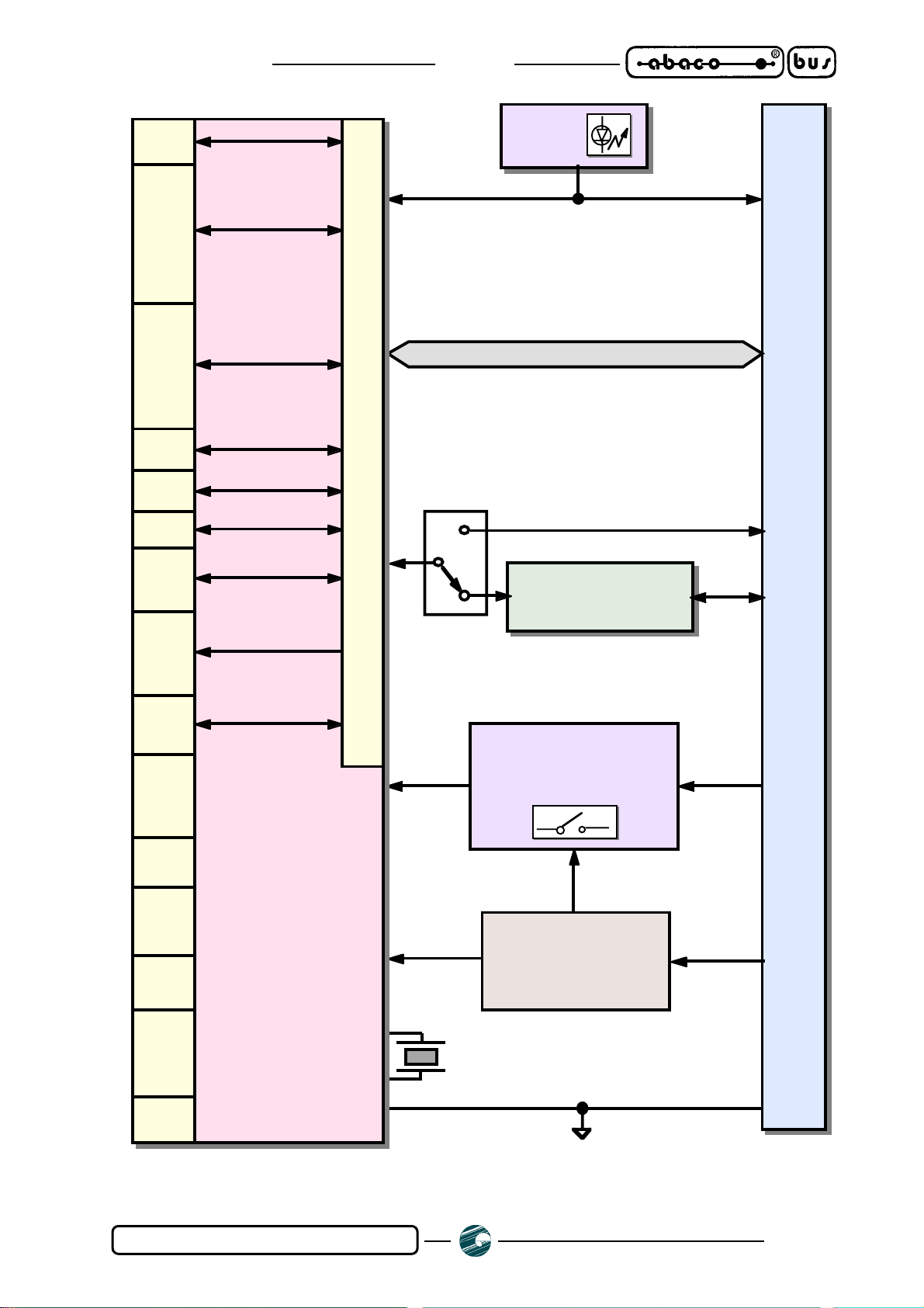
Here follows a description of the board's functional blocks, with an indication of the operations
performed by each one. To easily locate such section on verify their connections please refer to figure
1.
Page 4
Tele Web Controller Rel. 5.00
ITALIAN TECHNOLOGY grifo
®
6 Lines
CCU
7 Lines
ANALOG
COMPARATOR
2 Lines
COUNTER
PWM, TIMER
2 Lines
I2C
2 Lines
INT
4 Lines
SPI
2 Lines
UART
LED
1 signals
20 signals
Internal MUX
2 signals
(TTL serial line)
RS 232 DRIVER
protection ±15 kV
KEYPAD
I/O
PORT
DOG
WATCH
RTC
8 KB
FLASH
RAM
768 B
512 B
EEPROM
8 Lines
23 Lines
CPU
28 pins socket CN1
WORKING MODE
SELECTOR
(RUN/DEBUG)
WIDE RANGE
POWER SUPPLY
SECTION
2.6 ÷ 20 Vdc
P89LPC932
CLK
Tele Web Controller Rel. 5.00
FIGURE 1: BLOCKS DIAGRAM
Page 5

grifo
®
ITALIAN TECHNOLOGY
INTERNET INTERFACE
Internet interface is module Micro Web Server, a real HTTP server based on the resources of a
microcontroller and capable to connect to any local network or router through the Ethernet interface.
This module features several on board resources, for a complete description please refer to the Micro
Web Server.
In detail, RS 232 interface of Micro Web Server is used to communicate to GPC® control card and
to reach the resources of other peripheral modules.
OUTPUT SECTION OF ZBR
This section can feature 4, 8 ,16 or 32 latched output signals, according to the model ordered.
Each output signal is visualized through a LED and controls a 3 A relay, normally open, provided
with MOV 24 Vac noise suppressor.
These signals can be completely driven by the icons on the commands Web page, which also show
the outputs status using a different color.
Clicking on the icon of a signal complements its status.
OUTPUT SECTION OF ZBT
This section can feature 4, 8 ,16 or 32 latched output signals, according to the model ordered.
Each output signal is galvanically isolated, visualized through a LED and controls a not continuous
4 A Open Collector 45 Vdc Darlington Transistor, provided with suppression diode.
These signals can be completely driven by the icons on the commands Web page, which also show
the outputs status using a different color.
Clicking on the icon of a signal complements its status.
INPUT SECTION OF ZBT AND ZBR
This section can feature 8, 16, 24 or 32 input signals, according to the model ordered.
Each input signal is galvanically isolated by type NPN optocouplers and visualized through a LED.
Above mentioned optocouplers must be supplied through a tension +Vopto generated by on board
supply section.
Different status of each input is indicated using different colors.
POWER SUPPLY SECTION
Tele-Web features an efficent power supply circuitery that can accept a wide range of input tensions
and generates the required +5 Vdc voltage to supply output and logic sections in every load condition
and also generates the +Vopto voltage required by the Input optocouplers.
Please refer to ZBx manual for further information.
Page 6
Tele Web Controller Rel. 5.00

ITALIAN TECHNOLOGY grifo
®
FIGURE 2: PHOTO OF TELE WEB
Tele Web Controller Rel. 5.00
Page 7

grifo
®
ITALIAN TECHNOLOGY
TECHNICAL FEATURES
GENERAL FEATURES
On board resources: 1 Ethernet interface 10 Mbit/sec
from 4 to 24 digital transistor or relays outputs
from 8 to 32 optocoupled inputs
1 Real Time Clock (optional)
8 analog inputs for A/D converter (optional)
Memories: 2 KBytes FLASH EPROM for code (on TWC)
502 Bytes RAM for user data (on TWC)
502 Bytes EEPROM for user data (on TWC)
32 KBytes serial EEPROM for code and HTML (on TWC)
24 KBytes RAM for data logger (optional)
CPU: on GPC®, depends on the model ordered (*)
on TWC, Atmel 90S8515
Clock frequency: on GPC®, depends on the model ordered
on TWC, 8 MHz
PHYSICAL FEATURES
Size: 72 x 155 x 109 mm + length of ZBx (**)
Weight: 260 g + weigth of ZBx (**)
Connectors: CON1: plug 8 ways 90 degreeses for Ethernet 10BaseT
X3: D-type 9 ways 90 degreeses for RS 232
CN3A: D-type 9 ways 90 degreeses for RS 232
CN3B: D-type 9 ways 90 degreeses for RS 232
several quick release screw terminal connector (**)
Temperature range: from 0 to 50 centigrad degreeses
Relative humidty: 20% up to 90% (without condense)
(*) For further information, please refer to manual of GPC® ordered
(**) For further information, please refer to manual of ZBx ordered
Page 8
Tele Web Controller Rel. 5.00

ITALIAN TECHNOLOGY grifo
®
ELECTRIC FEATURES
Power supply: depends on ZBx ordered (**)
Current consumption: 5 mA + GPC® consumption (*) + ZBX consumption (**)
Analog inputs range: optional feature, depends on GPC® ordered (*)
Analog inputs impedance: optional feature, depends on GPC® ordered (*)
(*) For further information, please refer to manual of GPC® ordered
(**) For further information, please refer to manual of ZBx ordered
Tele Web Controller Rel. 5.00
Page 9

grifo
®
ITALIAN TECHNOLOGY
INSTALLATION
This chapter describes the hardware and software structure and all the steps to take for connecting
it to the netword, configure the PC and become operational.
MATERIAL REQUIRED
Tele-Web is made of three modules, all included in delivery:
-Micro Web Server; this modules is the interface to Ethernet network, in addition it runs the
TCP/IP stack and the HTTP server, it also stores HTML pages and images
- GPC®; this is the bridge between Micro Web Server and peripheral module, it runs the proper
telecontrol firmware (read the inputs, sets the outputs, etc.)
-ZBR/ZBT; this is the peripheral module featuring optocoupled inputs and relay or transistor
NPN (or PNP) outputs in a variable number, according to the model
This additional material not included in delivery is also required:
- Power supply cable
- 10BaseT type 5 Ethernet cable (straight or crosslink, ask the netword administrator)
- Serial line plug cable to connect the PC (grifo® listing code CCR.plug9F)
POWER SUPPLY
To supply the structure, it is enough to connect CN2 of ZBx peripheral module to the power supply
source.
According to the ZBx model and its configuration, power supply source can be quite different.
Please refer to ZBx manuals for further information.
Page 10
Tele Web Controller Rel. 5.00

ITALIAN TECHNOLOGY grifo
FIGURE 3: SNAPSHOT OF MICRO WEB SERVER
®
FIGURE 4: SNAPSHOT OF ZBR 168
Tele Web Controller Rel. 5.00
Page 11

grifo
®
ITALIAN TECHNOLOGY
SOFTWARE INSTALLATION
Tele-Web includes the complete delivery of Micro Web Server, shown in figure 5.
This delivery includes the Micro Web Server development CD and the sources of Tele Web Controler
firmware (TWC11.c, TWC11.mak, TWC11.pwp, IP plus all the files with *.htm and *.gif extension).
To install the basic developmnet system, it is enough to unzip the content of file pwdev.zip, that can
be found in the Micro Web Server development CD, into a folder.
NOTE: The resulting pathname must not contain space characters.
Example: unzip into the folder C:\pwdev\ is OK.
unzip into the folder C:\Web Software\ is wrong.
In the rest of the manual, the selected folder for software installation is C:\pwdev\.
After unzipping, to complete the installation, the following commands must be typed in a DOS
window or in the commands prompt:
C:>set PWDEV=C:\PWDEV
C:>set PATH=%PATH%;%PWDEV%\bin
Whenever the DOS window or the commands prompt is closed, the previous commands must be
typed again.
For greater comfort, the commands can be written in a batch file.
LOW LEVEL CONFIGURATION
Tele-Web is delivered already configured and ready to work.
The low level configuratin allows to specify:
-Which ZBR/ZBT peripheral module is used
- The password to access the system
The final user may want to change the low level configuration to modify the sytem password.
To change other elements of the low level configuration may lead to system malfunctions.
Please remark that any change to the configuration is immediatly reversible, except the labels
deletion.
Page 12
Tele Web Controller Rel. 5.00

ITALIAN TECHNOLOGY grifo
®
FIGURE 5: MICRO WEB SERVER COMPLETE DELIVERY
Tele Web Controller Rel. 5.00
Page 13

grifo
®
ITALIAN TECHNOLOGY
TO ENTER THE LOW LEVEL CONFIGURATION:
1. Connect the serial line of Tele-Web (connector plug CN3A of GPC® module) to a terminal
emulator or to a PC disconnecting the serial cable and connecting a plug serial cable (code of
grifo® listing CCR.plug9F)
2. On the PC, start a terminal emulator and configure it for 19200 Baud, 8 bit of data, 1 stop bit,
no parity
3. Switch off supply of Tele-Web
4. Enable low level configuration (see next table)
5. Supply Tele-Web
6. From the screen that appears on terminal emulator, select A
7. Type old password
8. Type new password
9. Exit from menu
10. Switch off supply of Tele-Web
11. Enable normal working mode (see next table)
12. Disconnect the plug cable to the PC, reconnect the cable already present before and supply the
Tele-Web
GPC®
CARD
Enable configuration mode Enable normal working mode
Page 14
GPC®
324D
J1 Open J1 Connected
FIGURE 6: LOW LEVEL CONFIGURATION
Tele Web Controller Rel. 5.00

ITALIAN TECHNOLOGY grifo
®
ZBX MAPPING ADDRESS
To make the ZBx module reachable from the tele control firmware it is essential that its address on
ABACO® I/O BUS is the correct one for the GPC® module used.
For further information about ABACO® I/O BUS and about mapping addresses please refer to the
manuals of GPC® and ZBx modules used.
Table of correct addresses is:
GPC®
CARD
GPC®
324D
Base Address
of ZBx
JAddr Jumpers group
00H All jumpers connected
FIGURE 7: ZBX MAPPING ADDRESS
FIGURE 8: SNAPSHOT OF A GPC® 324D
Tele Web Controller Rel. 5.00
Page 15

grifo
®
ITALIAN TECHNOLOGY
HIGH LEVEL CONFIGURATION
Before proceeding here, assure to have taken all the steps described in the paragraph “Software
Installation”.
High level configuration allows to set the IP address of Web interface.
In order to to this, it is essential to connect CON1 of Micro Web Server to the Ethernet local network
through an appropriate cable and obtain a free IP address.
If specialized personnell is managing the network, ask the network administrator.
IP addres is assigned executin the SETIP command in the DOS window or command prompt of a
PC connected to the same network of Tele-Web and changing the content of the file called IP in the
sources folder of Tele Web Controller.
For example, if the free IP obtained is 192.168.168.123, the command to type is:
SETIP 0:1:2:3:4:5 192.168.168.123
While in the file called IP just replace “192.168.168.123” to the address already present.
In the same DOS window or command prompt, to make the Tele-Web visible to the PC, type:
ROUTE ADD 192.168.168.123 <Address of PC>
Being, like in the previous example, the address of Tele-Web 192.168.168.123.
To obtain the address of PC, you may execute the utility winipcfg and find the address of Ethernet
adapter or ask the netword administrator.
This latter command must be retyped whenever the DOS window or a command prompt is closed.
After doing this, the command:
PING 192.168.168.123
should receive a response from the Tele-Web.
In this case, the system is ready for working.
Page 16
Tele Web Controller Rel. 5.00

ITALIAN TECHNOLOGY grifo
®
UTILIZATION
LOGIN
Before any other operation, server authentication is required (login).
Assiming 192.168.168.123 as the IP assigned to the Tele-Web, run the preferred browser (e.g.
Internet Explorer, Opera, Netscape, etc.) and type in the addres box:
http://192.168.168.123.
By default, no passowrd is set in the system as it is delivered.
Tele-Web responds with the page shown in figure 9, type the password (if present) in the specific
test obx or press immediatly the button if no password is set.
NOTE: For further information about how to set the password, please refer to paragraph “LOW
LEVEL CONFIGURATION”.
If the (optional) password it typed correctly, Tele-Web enables the commands page, from which it
is possible to control all the features of the application described in the paragraph “GENERAL
INFORMATION”.
If the password is not typed correctly, the Tele-Web enters in a idle mode for about one minute,
during which any command is ignored.
This way, illegal access attempts are heavily obstacolated.
Tele Web Controller Rel. 5.00
FIGURE 9: LOGIN
Page 17

grifo
®
ITALIAN TECHNOLOGY
OUTPUT COMMANDS
Entering the commands page, it is possible to control the status of transistor or relays outputs and
optocoupled inputs of ZBR/ZBT module.
Commands page is shown in figure 10, it is automatically updated every 5 seconds.
If the peripheral module installed is not ZBR/ZBT 168, you may see a different number of inputs and
outputs respect to figure 10.
Each signal features a 31 characters long label printed near the icon that shows the signal status.
When delivered, Tele-Web has all the labels set to a null string, to set them please refer to paragraph
“LABELS MANAGEMENT”.
When an output is enabled (relay contact closed or transistor conducting), this fact is indicated
painting in red its label and showing the image stored in the file called “on.gif”.
By default, the image shows the writing “ON”.
When an output is disabled (relay contact open or transistor not conducting), it is indicated showing
the image stored in the file called “off.gif”.
By default, the image shows the writing “OFF”.
To modify the images “on.gif” and “off.gif” please refer to paragraph “PERSONALIZATIONS”.
To complement the status of an output, it is enough to click on the corresponding icon.
So, clicking on the icon of an output enabled, this will be disabled, and viceversa.
INPUT COMMANDS
Entering the commands page, it is possible to control the status of transistor or relays outputs and
optocoupled inputs of ZBR/ZBT module.
Commands page is shown in figure 10, it is automatically updated every 5 seconds.
If the peripheral module installed is not ZBR/ZBT 168, you may see a different number of inputs and
outputs respect to figure 10.
Each signal features a 31 characters long label printed near the icon that shows the signal status.
When delivered, Tele-Web has all the labels set to a null string, to set them please refer to paragraph
“LABELS MANAGEMENT”.
When an optocoupled input is enabled (contact closed), this fact is indicated painting in green or
yellow (whether the bit belongs to a high byte or not) its label and showing the image stored in the
file called “on.gif”.
By default, the image shows the writing “ON”.
When an input is disabled (contact open), it is indicated showing the image stored in the file called
“off.gif”.
By default, the image shows the writing “OFF”.
To modify the images “on.gif” and “off.gif” please refer to paragraph “PERSONALIZATIONS”.
Page 18
Tele Web Controller Rel. 5.00

ITALIAN TECHNOLOGY grifo
®
FIGURE 10: COMMANDS PAGE OF ZBX 168
FIGURE 11: LABELS MANAGEMENT
Tele Web Controller Rel. 5.00
Page 19

grifo
®
ITALIAN TECHNOLOGY
LABELS MANAGEMENT
Clicking the link “Change signals names” you may access the signals names management page.
Modules ZBR/ZBT of grifo® feature up to 24 relays or transistor outputs and up to 32 optocoupled
inputs.
The page shows all the 56 signals and their names even if the hardware used does not feature them
because the firmware manages all the names in any case.
To change the name of a signal, just click on it with the mouse (as in figure 12), write the new name
in the textbox and pres sthe button.
The result will be immediatly visible in this page and in the commands page.
REAL TIME CLOCK MANAGEMENT (OPTIONAL)
An optional version of grifo® Tele-Web features a Real Time Clock backed by a Lithium battery
and capable to manage day, month, year, hour, minutes and seconds.
Managenent of time is performed through a comfortable specific Web page available only for who
orders this option and described in detail in a specific manual.
Shortly, the above mentioned Web page allows to read and set date and time and to save or load such
settings to/from a file on the PC.
DATA LOGGER MANAGEMENT (OPTIONAL)
An optional version of grifo® Tele-Web features a data logger that uses the GPC® module local
memory backed by a Lithium battery.
This option can be ordered together with the previous one, to make possible to store a timestamp
matched with other data.
Managenent of data logger and ring buffer memory content is performed through a comfortable
specific Web page available only for who orders this option and described in detail in a specific
manual.
Shortly, the above mentioned Web page allows to get and set the sampling frequency and the
presence of a timestamp, to reset or to read the content of the memory and to save or load such settings
to/from a file on the PC.
In detail, content of memory can be saved in a Excel compatible format, with cell names decideable
by the user.
Page 20
Tele Web Controller Rel. 5.00

ITALIAN TECHNOLOGY grifo
®
FIGURE 12: CHANGE SIGNALS NAMES
Tele Web Controller Rel. 5.00
Page 21

grifo
®
ITALIAN TECHNOLOGY
ANALOG INPUTS MANAGEMENT (OPTIONAL)
An optional version of grifo® Tele-Web features eight analog inputs.
Managenent of analog inputs is performed through a comfortable specific Web page available only
for who orders this option and described in detail in a specific manual.
Shortly, the above mentioned Web page allows to read the inputs, to enable or disable the saving of
the inputs to the (optional) ring buffer memory and to save the contente of this memory in a Excel
compatible format, with cell names decideable by the user.
Page 22
Tele Web Controller Rel. 5.00

ITALIAN TECHNOLOGY grifo
®
PERSONALIZATIONS
To personalize the Tele-Web, a good knowledge of C programming language, of Micro Web Server
scripting language PCode and grifo® hardware is required.
If you want a custom firmware in short times, please contact grifo® directly through our Web sites
http://www.grifo.it or http://www.grifo.com.
Before continuing, instructions descibed in paragraphs “SOFTWARE INSTALLATION” and
“HIGH LEVEL CONFIGURATION” must be followed.
To make any kind of changes to the content of HTML pages or to the behaviour of firmware it is
essential to recompile the software project.
Software project is made of two modules:
-GPC® software module: it is written in C using the compiler µC/51; this part of firmware
receivs commands through the GPC® RS 232 serial line (connector CN3A) and manages
outputs, inputs and all other features
-Micro Web Server software modul: it is written in PCode and compiled using the sofware
development tools of Micro Web Server (please refer to chapter “SOFTWARE
INSTALLATION”); it manages the Internet interface of the system, user commands and Web
response pages
The compilation procedure is beyond the purposes of this manual, pleare refer to Micro Web Server
specific documentation for further information.
The user can easily change some graphic elements of the project, following paragraphs give some
information about this purpose.
Changing the behaviour of the firmware is more complex and requires a deep study of the project
and of the development system, in specific of the following files:
-PDF document pwproj.pdf, in sub-folder /docs of Micro Web Server installation folder
-PDF document pw1_pcode.pdf, in sub-folder /docs of Micro Web Server installation folder
- Source code of Micro Web Server software module: TWC11.pwp
- Source code of GPC® software module: TWC11.c
The first two files contain detailed instructions on how to make a Micro Wev Server software project
and to write PCode scripts.
Other two files contain several comments that explain how the modules work, allowing to understand
and so to change their behaviour.
Further information about compiler µC/51 can be found at: http://www.wickenhaeuser.de.
Further information about Micro Web Server firmware development system can be found at:
http://www.picoweb.net and http://www.achatz.nl.
Tele Web Controller Rel. 5.00
Page 23

grifo
®
ITALIAN TECHNOLOGY
PERSONALIZATION OF ICONS
Tele-Web, in the basic version without options, uses three icons:
1. To show the status ON of an input or an output, the corresponding image is on.gif
2. To show the status OFF of an input or an output, the corresponding image is off.gif
3. To show that an input or an output is not available, the corresponding image is na.gif
To personalize them, just replace these images with the ones you want without changing their
names, and to recompile the project.
PERSONALIZATION OF HTML PAGES
Tele-Web, in the basic version without options, uses three Web pages:
1. TWCMain.htm for login
2. TWCCommands.htm for commands management
3. TWCLabels.htm for labels management
All the elements of HTML language (tags) can be changed by an HTML experienced user, without
changing the files names.
In specific, name enclose in back-quotes (for example: `list_lables.cgi`) are required for the project
correct working and must never be changed.
For further information, please refer to PDF documents pwproj.pdf and pw1_pcode.pdf, in subfolder
/docs of Micro Web Server installation folder.
Page 24
Tele Web Controller Rel. 5.00

ITALIAN TECHNOLOGY grifo
®
APPENDIX A: ALPHABETICAL INDEX
SYMBOLS
+VOPTO 6
10BASET 10
A
A/D CONVERTER, OPTIONAL 8
ANALOG INPUTS 9
ANALOG INPUTS MANAGEMENT (OPTIONAL) 22
C
CLOCK 8
CONNECTORS 8
CPU 8
CURRENT CONSUMPTION 9
D
DARLINGTON 6
DATA LOGGER MANAGEMENT (OPTIONAL) 20
DATA LOGGER, OPTIONAL 8
E
EEPROM 8
EPROM 8
ETHERNET 6, 8, 10
G
GPC®10
H
HIGH LEVEL CONFIGURATION 16
HTTP 6
I
INPUT 6
INPUT COMMANDS 18
INTERNET 6
IP ADDRESS 16
GMB HR168 & GMM AC0 Rel. 5.00
Page A-1

L
LABELS MANAGEMENT 20
LED 6
LOGIN 17
LOW LEVEL CONFIGURATION 12
M
MICRO WEB SERVER 6, 10
MOV 6
N
NPN 6, 10
O
OPEN COLLECTOR 6
OPTOCOUPLERS 6
OUTPUT 6
OUTPUT COMMANDS 18
grifo
®
ITALIAN TECHNOLOGY
P
PASSWORD 12, 14, 17
PERSONALIZATION OF HTML PAGES 24
PERSONALIZATION OF ICONS 24
PERSONALIZATIONS 23
PNP 10
POWER SUPPLY 6, 10
R
RAM 8
REAL TIME CLOCK MANAGEMENT (OPTIONAL) 20
REAL TIME CLOCK, OPTIONAL 8
RELATIVE HUMIDTY 8
RELAY 6, 8
RESOURCES 8
S
SERIAL EEPROM 8
SETIP, COMMAND 16
SIZE 8
SOFTWARE 12
Page A-2
GMB HR168 & GMM AC0 Rel. 5.00

ITALIAN TECHNOLOGY grifo
T
TEMPERATURE RANGE 8
TRANSISTOR 6, 8
V
VERSION 3
W
WEIGHT 8
Z
ZBR 6, 10, 18
ZBT 6, 10, 18
®
GMB HR168 & GMM AC0 Rel. 5.00
Page A-3

grifo
®
ITALIAN TECHNOLOGY
Page A-4
GMB HR168 & GMM AC0 Rel. 5.00
 Loading...