

Page 1

www.Griffin-Stands.com
Crank Up Truss
Stand
www.Griffin-Stands.com
www.Griffin-Stands.com
Griffin™ stands and accessories are manufactured
in several innovative factories responsible for
developing products that address the newest
needs and trends of the current market. We take
pride in the Griffin™ brand and endeavor to be on
the forefront of the musical stands and musical
and lighting accessoriesmarket.
Performance Issue, Uneven or Unstable- Make
sure all nuts and bolts are tight on the product. If they
are, then loosen all nuts and bolts 1 full turn counterclockwise, then go back and tighten each bolt only ½
turn tight. Then do a final tighten turn for another ½
turn tight. Next, Make sure there are not any missing
nuts or bolts. Third, ensure all parts on the product
are not broken or defective. Finally, Re-read the
assembly instructions or watch the product
demonstration video to ensure you have correctly
assembled or are using the product properly with
factory specifications.
Missing Parts- The pictures, videos and images
shown in this manual might have changed style or
count due to the product being redesigned. So in rare
cases the part may no longer be included or of a
different style. However, if you think you are missing
a part that is necessary to the assembly and use of
your product, then first carefully double check all
packaging for any parts you think are missing. Some
parts might be hiding in the packaging or loose in an
inner box.
User Manual
M od e l # L K 35 3
Griffin | 11408 Hwy 64 W, Tyler, TX 75704 |
info@griffin-stands.com | www.Griffin-
Stands.com
For current product specifications, please to go
www.griffin-stands.com and type the model number
into the search bar. Locate the product listing to view
the current factory specifications.
Thank you for purchasing the Griffin Crank Up Truss
Stand. Your product comes with a 1 year factory
warranty from purchase date. Please read all
assembly instructions prior to assembling your new
cart. Pictures that may aid in assembly can be found
by going to www.griffin-stands.com and typing LK353
into the search bar.
Page 2
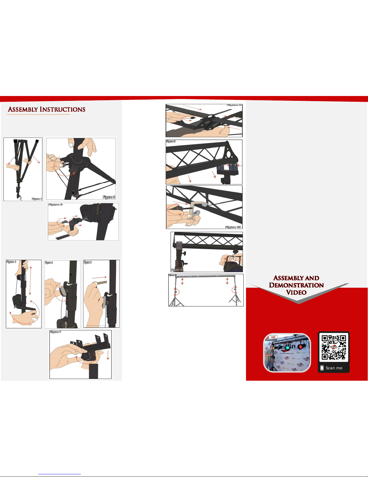
Step 3 – Turn the handle to crank up the system, tighten
the knob and insert the locking pin through the hole to
secure the height of the stand, see Figure 4, 5 and 6.
Step 4 – At the
top of the stand,
slide in the T-
adapter and
tighten the knob
to secure the
adapter on top
(See Figure 7) and
set aside.
Step 1 – Take the stand and turn it upside down to have
more leverage in spreading the legs. Spread the legs
approximately 36” (91.5cm) apart. (See Figure 1) Turn the
knob tight near thebase to secure the legs. (See Figure 2)
Step 5 – Take the
trusses and
connect each
with the bolts
provided as
shown in Figure
8. Once the
trusses are
connected and
securely fastened
slide each end on
the T-adapters of
the stand (See
Figure 9).
Step 6 – Figure
10 and 11 shows
how to mount
the c-clamps
provided and
how to mount
light fixtures.
Please scan the QR Code below for the product
demonstration video. Or go to the URL shown here and find
the product video. www.Griffin-Stands.com/Videos
Step 2 – Take the
handle and insert it
through the bolt
beside the cranks
and secure with a
wing nut as shown
in Figure 3.
Step 7 – To raise
the truss, crank the
handles. It is very
important to raise
the truss evenly on
both sides. This is
much easier done
with two people. If
you are doing this
by yourself, do not
raise more than
one inch per side at
a time. Place the
safety pins in place
and tighten the set
knob located on the
upper pulley
assembly. The
holes for the safety
pin are located on
the shaft directly
above the knob.
As a general rule the higher the height of the system, the
less stable the stand will be and less weight can be
mounted. Additionally, spread the legs wider for a more
secure and balanced stand especially if the stand will be
carrying heavy items. The wider the legs are the more
stable the stand will be. Also, make sure that the weight is
evenly distributed throughout the stand system. Heavier
equipment loads need to be installed near the tripod
stand, while lighter ones can be mounted on the middle
truss or further away from the tripod stand. If your system
is a 3-truss section setup, then always keep the weight
load of the middle truss limited to only 50% of the weight
that is on connecting trusses. This would mean your
middle truss will only half ½ of the weight on it as the
connecting trusses. After you have mounted your
equipment, always check the stability of the weight load.
Step 9 - To lower the stand, loosen the knob and push
down on the post and turn the handle counter clockwise.
Depending on how often you raise and lower the stand
and/or open and close the tripods some maintenance is
required. Periodically lightly grease the sprockets located
on the on the crank assembly using petroleum jelly or
other lightweight grease. Also, periodically check and
tighten the nuts and bolts located on the tripod section.
How often depends on how much you open and close the
tripod. Failure to do this important maintenance step may
result in the loss of a bolt which will cause a dangerous
condition that may cause injury to yourself or others. If
the post that lifts the truss squeaks you can use a
lightweight spray lubricant such as WD40 .
Step 8 - For safety reasons,
please always make sure to test
the stability and safety of the
product before use. Double
check all nuts and bolts, knobs
and connectors, make sure that
these are tight and securely
fastened before use of your
product. Test the product under
light use or light loads the first
time to confirm assembly and
structure of the product is
correct.
 Loading...