

Page 1

www.Griffin-Stands.com
Rackmount
Road Case
www.Griffin-Stands.com
www.Griffin-Stands.com
Griffin™ stands and accessories are manufactured
in several innovative factories responsible for
developing products that address the newest
needs and trends of the current market. We take
pride in the Griffin™ brand and endeavor to be on
the forefront of the musical stands and musical
and lighting accessoriesmarket.
Performance Issue, Uneven or Unstable- Make
sure all nuts and bolts are tight on the product. If they
are, then loosen all nuts and bolts 1 full turn counterclockwise, then go back and tighten each bolt only ½
turn tight. Then do a final tighten turn for another ½
turn tight. Next, Make sure there are not any missing
nuts or bolts. Third, ensure all parts on the product
are not broken or defective. Finally, Re-read the
assembly instructions or watch the product
demonstration video to ensure you have correctly
assembled or are using the product properly with
factory specifications.
Missing Parts- The pictures, videos and images
shown in this manual might have changed style or
count due to the product being redesigned. So in rare
cases the part may no longer be included or of a
different style. However, if you think you are missing
a part that is necessary to the assembly and use of
your product, then first carefully double check all
packaging for any parts you think are missing. Some
parts might be hiding in the packaging or loose in an
inner box.
User Manual
M od e l # DE Q 0 2
Griffin | 11408 Hwy 64 W, Tyler, TX 75704 |
info@griffin-stands.com | www.Griffin-
Stands.com
For current product specifications, please to go
www.griffin-stands.com and type the model number
into the search bar. Locate the product listing to view
the current factory specifications.
Thank you for purchasing the Griffin Rackmount Road
Case. Your product comes with a 1 year factory
warranty from purchase date. Please read all
assembly instructions prior to assembling your new
cart. Pictures that may aid in assembly can be found
by going to www.griffin-stands.com and typing DEQ02
into the search bar.
Page 2
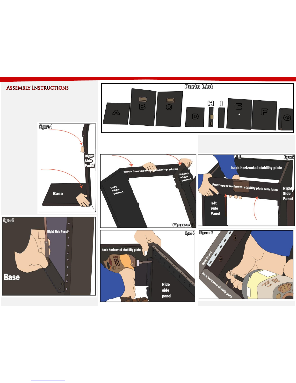
Step 2 – Take Back Horizontal Plate (Part I) and place it on
the top of the assembly done in Step 1 and screw together
(See Figure 3 and 4)
Step 1 – As shown in
Figure 1, take the
base (Part A) and
Right Side Panel (Part
C). Connect the panel
on the side of the
base perpendicularly
and screw down (See
Figure 2) Do the
same thing by taking
the Left side Panel
(Part B) and
connecting over to
the other side.
Parts List
A. Base F. Front Panel
B. Left Side Panel G. Lid
C. Right Side Panel H. Front Upper Horizontal Plate
D. Shelf I. Back Horizontal Plate
E. Back Panel
Step 3 – Now, take Front Upper Horizontal Plate (Part H)
and connect in front of the stand screw in together on
the corners (See Figure 5 and 6)
Page 3

Step 6 – Figure 11 shows how to place the wheels.
Place the metal plate inside (opposite side of the caster
wheels) and align the wheels outside. There should be
a pre-drilled hole that will guide you to secure the
wheels with bolts, nuts and washers.
Please scan the QR Code below for the product
demonstration video. Or go to the URL shown here and find
the product video. www.Griffin-Stands.com/Videos
Step 4 – Get the lid (Part G) and place on top. Behind the
lid (Part G) are the hinges that is attached to Back
Horizontal Plate (Part I) using a screw as shown in Figure
7. Now in between Back Horizontal Plate (Part I) and the
side panels screw in the L-Brackets for a more secure
back horizontal plate. (See Figure 8). Attach the four “L”
brackets. The front “L” brackets should be attached 1”
(2.5cm) from the top. The back “L” brackets should be
attached 2” (5cm) from the top.
Step 5 – Turn the stand to the side, at the base (Part A)
measure and divide to three sections. Measuring from
the front, the leading edge of the bracket closest to the
front should be 6” (15.2cm) and the leading edge of the
bracket closest to the back should be 13” (33cm). This is
where you will drill and screw in the L-Brackets. Do the
same step on the other side as seen on Figure 9. Also,
while the stand laying on one side you can install the
chrome corner brackets as shownin Figure 10.
Step 7 – Place the middle shelf (Part D) inside. There is a
support tab inside the stand where the shelf rests.
(Refer to Figure 12)
Page 4

Please scan the QR Code below for the product
demonstration video. Or go to the URL shown here and find
the product video. www.Griffin-Stands.com/Videos
Step 8 – Now take Back Panel (Part E) and place it on the
back of the stand. This is secured by a Velcro (See Figure
13). And do the same thing for Front Panel (Part F). For
the Front Panel (Part F), make sure that the ribbon is
flipped outside so that removing the front panel is easy.
Step 9 – Figure 14 shows how to lock and unlock the top
lid. The top lid can be removed if you tilt it all the way to
the back. It can be removed from the hinges by design.
Step 10 - For safety reasons, please always make sure to
test the stability and safety of the product before use.
Double check all nuts and bolts, knobs and connectors,
make sure that these are tight and securely fastened
before use of your product. Test the product under light
use or light loads the first time to confirm assembly and
structure of the product is correct.
Your rack case has many great features. Let’s talk about
a couple. To use the locking latch, simply turn the knob
on the bottom half of the latch counter clockwise until
the latch is fully extended. Then push the latch forward
until the latch goes into the slot on the upper half of the
latch found on the lid. Then turn the knob clockwise to
hold it in place. It even comes with a place you can put a
lock on your case. The front panel and back panel can be
removed for easy access to your equipment. The back
panel even has a hole for running your cables through
for a nicer and neater looking setup.
Please note that if your mixer is smaller than the minimum
capacity of the top shelf, you will need a wider rack ears to
be able to mount your mixer. Place heavy equipment at
the bottom and lighter equipment at the top. See Figure
15 for how a mixer should look like installed.
Two of your casters have locking wheels. To use the locks,
simply push down on the “brake” that sticks out from the
wheel. To release the “brake” just pull up on it. This is a
great feature that you’ll be using often. Your DEQ-02
comes with pre-installed rack mount brackets and the
screws to install your equipment. Use the included screws
to attach the “wings” of your rack mount equipment to the
rack rails. The top will hold a “flat” or “slider” sound board.
 Loading...