

Page 1

www.Griffin-Stands.com
Studio
Microphone
Boom Stand
www.Griffin-Stands.com
www.Griffin-Stands.com
Griffin™ stands and accessories are manufactured
in several innovative factories responsible for
developing products that address the newest
needs and trends of the current market. We take
pride in the Griffin™ brand and endeavor to be on
the forefront of the musical stands and musical
and lighting accessoriesmarket.
Performance Issue, Uneven or Unstable- Make
sure all nuts and bolts are tight on the product. If they
are, then loosen all nuts and bolts 1 full turn counterclockwise, then go back and tighten each bolt only ½
turn tight. Then do a final tighten turn for another ½
turn tight. Next, Make sure there are not any missing
nuts or bolts. Third, ensure all parts on the product
are not broken or defective. Finally, Re-read the
assembly instructions or watch the product
demonstration video to ensure you have correctly
assembled or are using the product properly with
factory specifications.
Missing Parts- The pictures, videos and images
shown in this manual might have changed style or
count due to the product being redesigned. So in rare
cases the part may no longer be included or of a
different style. However, if you think you are missing
a part that is necessary to the assembly and use of
your product, then first carefully double check all
packaging for any parts you think are missing. Some
parts might be hiding in the packaging or loose in an
inner box.
User Manual
M od e l # A PS T 01
Griffin | 11408 Hwy 64 W, Tyler, TX 75704 |
info@griffin-stands.com | www.Griffin-
Stands.com
For current product specifications, please to go
www.griffin-stands.com and type the model number
into the search bar. Locate the product listing to view
the current factory specifications.
Thank you for purchasing the Griffin Studio
Microphone Boom Stand. Your product comes with a
1 year factory warranty from purchase date. Please
read all assembly instructions prior to assembling
your new cart. Pictures that may aid in assembly can
be found by going to www.griffin-stands.com and
typing APST01 into the search bar.
Page 2
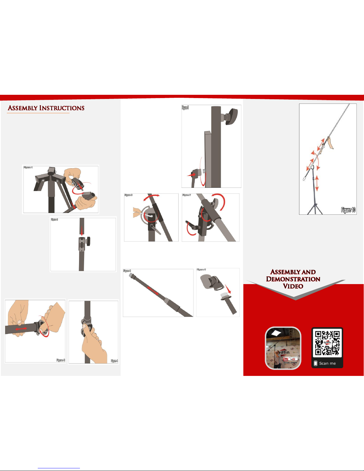
Step 4 – With the boom
pipe assembled, place it on
top of the stand assembly
by screwing it in together
with the turn knob as
shown in Figure 5 and 6.
With this assembled, the
turn knob controls the
angle of the boom pipe and
the knob on the boom pipe
can be loosened to adjust
the length of the boom.
(See Figure 7)
Step 1 – Take the stand and turn it upside down,
spread the legs. By doing this you will have more
leverage in spreading the legs wide. While the stand is
upside down take the wheels and screw on the bottom
of each leg. (See Figure 1). Make to screw in tightly by
using a wrench and even with all three wheels so the
stand wont wobble and willnot be leaning to one side.
Step 2 – Turn the
stand right side up
and slide the middle
pipe through the
middle. Secure this
by turning the knob
on the shaft. (See
Figure 2)
Step 5 - Take the tip of the boom pipe (extension) and
insert through the pipe of the boom, this will allow you to
mount the mic. Just screw in the mic handle at the tip as
shown in Figure 8.
Please scan the QR Code below for the product
demonstration video. Or go to the URL shown here and find
the product video. www.Griffin-Stands.com/Videos
Step 3 – Take the boom pipe and unscrew the knob so
that the boom pipe can be adjusted through as shown in
Figure 3. Tighten the knob back to secure (See Figure 4).
To ensure stability make sure the front of the boom is
placed over a leg of the tripod. This type of microphone
boom stand comes with a counter weight. If your stand is
wobbly or unstable, make sure that the legs are spread
wide or adjust the boom arm the opposite way and bring
down the height.
Step 6 – Figure 9 above shows how to screw in the
microphone clip. Use a microphone clip or shock mount
to mount your microphones.
Step 7 – Figure 10 shows the adjusting points of the
stand. The main stand has a handle to adjust the stands
height, the turn knob adjusts the angle, the knob near
the turn knob allows you to pull and push the main boom
pipe and near the top is an extending boom pipe as well.
Step 8 – For safety
reasons, please always
make sure to test the
stability and safety of the
product before use.
Double check all nuts and
bolts, knobs and
connectors, make sure
that these are tight and
securely fastened before
use of your product. Test
the product under light
use or light loads the first
time to confirm assembly
and structure of the
product is correct.
 Loading...