

Page 1

www.Griffin-Stands.com
Telescoping
Microphone
Stand
www.Griffin-Stands.com
www.Griffin-Stands.com
Griffin™ stands and accessories are manufactured
in several innovative factories responsible for
developing products that address the newest
needs and trends of the current market. We take
pride in the Griffin™ brand and endeavor to be on
the forefront of the musical stands and musical
and lighting accessoriesmarket.
Performance Issue, Uneven or Unstable- Make
sure all nuts and bolts are tight on the product. If they
are, then loosen all nuts and bolts 1 full turn counterclockwise, then go back and tighten each bolt only ½
turn tight. Then do a final tighten turn for another ½
turn tight. Next, Make sure there are not any missing
nuts or bolts. Third, ensure all parts on the product
are not broken or defective. Finally, Re-read the
assembly instructions or watch the product
demonstration video to ensure you have correctly
assembled or are using the product properly with
factory specifications.
Missing Parts- The pictures, videos and images
shown in this manual might have changed style or
count due to the product being redesigned. So in rare
cases the part may no longer be included or of a
different style. However, if you think you are missing
a part that is necessary to the assembly and use of
your product, then first carefully double check all
packaging for any parts you think are missing. Some
parts might be hiding in the packaging or loose in an
inner box.
Use r Manu al
M od e l # A P 3 6 14 / AP 3 6 0 7
Griffin | 11408 Hwy 64 W, Tyler, TX 75704 |
info@griffin-stands.com | www.Griffin-
Stands.com
For current product specifications, please to go
www.griffin-stands.com and type the model number
into the search bar. Locate the product listing to view
the current factory specifications.
Thank you for purchasing the Griffin Telescoping
Microphone Stand. Your product comes with a 1 year
factory warranty from purchase date. Please read all
assembly instructions prior to assembling your new
cart. Pictures that may aid in assembly can be found
by going to www.griffin-stands.com and typing
AP3614 / AP3607 into the search bar.
Page 2
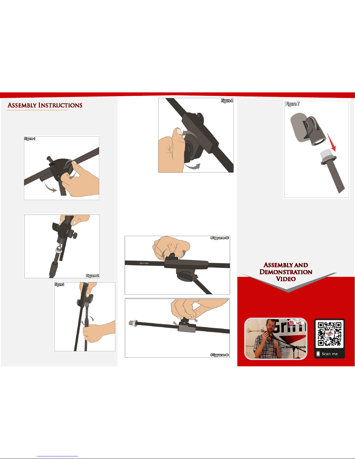
Step 4 – Loosen
the knob shown
in Figure 4 to
adjust the angle
of the boom
pipe.
Step 6 – Figure 7
shows how to screw
in the microphone
clip. Use a
microphone clip or
shock mount to
mount your
microphone.
Step 1 – Loosen the knob at the base by turning it
clockwise as shown on Figure 1. Expand and spread the
legs and tighten the knob to hold thelegs in place.
Step 2 – Take the boom arm, insert it in the top shaft
of the stand and screw it fully (see Figure 2).
Step 3 – To adjust the
height of the stand,
simply loosen the
hand knob near the
connection of the
boom piece then
adjust up or down the
inner pipe to your
preference and tighten
to hold in place (see
Figure 3).
Step 5 - To adjust the boom, loosen the knob located on
the left side of the boom and pull or push the boom
forward or backward, the tighten the knob to hold in
place as shown in Figure 5. This Microphone Stand has
an additional telescoping boom located near the
microphone. To extend or retract, loosen the knob
directly behind the microphone clip and extend or retract
the boom (See Figure 6). Tighten the knob to hold it in
place.
Please scan the QR Code below for the product
demonstration video. Or go to the URL shown here and find
the product video. www.Griffin-Stands.com/Videos
Step 7 – For safety reasons, please always make sure to
test the stability and safety of the product before use.
Double check all nuts and bolts, knobs and connectors,
make sure that these are tight and securely fastened
before use of your product. Test the product under light
use or light loads the first time to confirm assembly and
structure of the product is correct.
 Loading...