

Griffco Valve HP-Series User Manual

Griffco Valve Inc.
6010 N. Bailey Ave., Suite 1B
Amherst, NY 14226
Phone: 1 716 835-0891
Fax: 1 716 835-0893
HP-Series
Instruction
Manual
High Pressure Relief Valves
Call: 1 - 800 - GRIFFCO Website: www griffcovalve.com
INSG-2002-R0513 Revision Date: 05/06/13
INTRODUCTION
Y-STRAINER
GRIFFCO
CYLINDER
GRIFFCO BACK
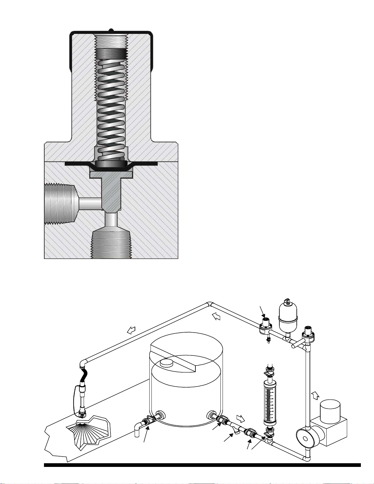
TYPICAL INSTALLATION
Griffco piston / diaphragm pressure relief
valves are designed to protect chemical feed
systems from over pressure damage caused
by defective equipment or a blockage in the
chemical feed line. Robust construction
ensures reliability in the rigorous service of
municipal and industrial applications. Wetted
materials include 316 SS, A 20 and Hast. C.
Available sizes: 1/4”, 3/8”,1/2”, 3/4" and 1”
OPERATION:
Griffco high pressure relief valves operate
when the pressure in the chemical system
exceeds the preset pressure of the valve.
The piston is held against the valve seat by
an internal spring. When the preset pressure
is exceeded the piston is forced up and the
chemical flows out the relief port, to drain or
back to the chemical tank. The valves are
pre-set on request, however they are field
adjustable from 350 - 2000 psi via the
adjustment screw. The relief valve should be
set approximately 10% higher than the
system operating pressure.
HP RELIEF VALVE
INJECTION
VALVE
DRAIN
VALVE
CHEMICAL
CONTAINER
SHUT OFF VALVE
ISOLATING BALL VALVES
PRESSURE VALVE
PULSATION
DAMPENER
GRIFFCO PRESSURE
RELIEF VALVE
RELIEF PORT
CALIBRATION
CHEMICAL
FEED PUMP
 Loading...