

Griffco Valve CC PVC User Manual
Griffco Valve Inc.
6010 N. Bailey Ave, Ste 1B
Amherst, NY 14226 USA
Phone: 1 800-474-3326
Fax: 1 716-835-0893
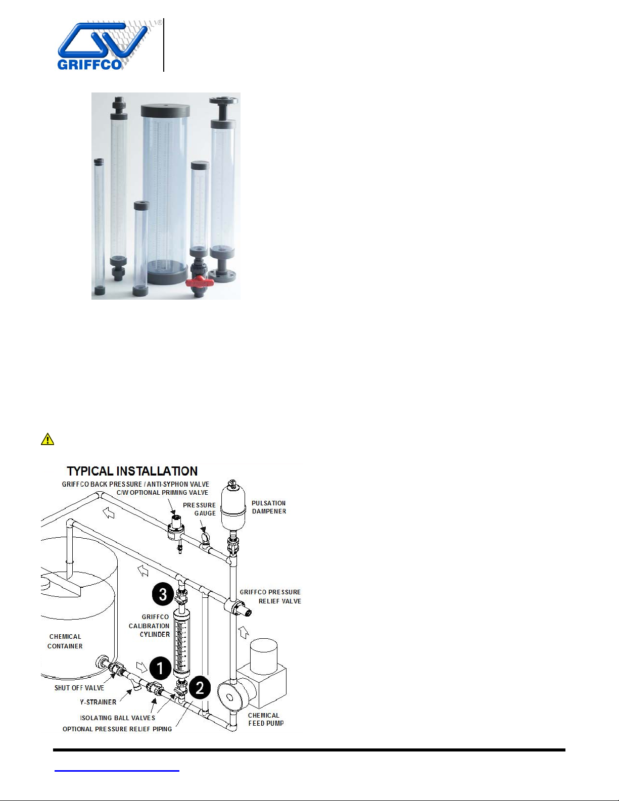
Installation Instructions:
Install the calibration cylinder in the suction line
before the chemical metering pump. Ensure that the
cylinder is vertical and level. For Sealed and EZClean configurations, two (2) isolating valves are
typically installed as per the drawing below. The top
of the cylinder should be vented back to the top of
the chemical container or to drain. The cylinder must
never be pressurized above 15 psi.
Caution! Max. cylinder pressure is 15 psi.
PVC CALIBRATION CYLINDERS
Installation & Operation Manual
Operating Instructions:
There are two (2) methods for using the calibration
cylinder, measuring volume or flow rate.
Method 1 – Volumetric. Any drawdown time may
be used: (Using the mL Scale)
1. Open isolating valves 1 and 2 to fill the cylinder to
the top mark on the scale (0 mL). Valve 3 is open
for venting.
2. Close isolating valve 1 from the tank on the suction
line. Leave isolating valves 2 and 3 on the
calibration cylinder open. Note the top needs to be
open to vent.
3. Turn on the chemical feed pump for a measured
drawdown time (seconds). Turn off the pump or
close valve 2 (first) and open valve 1 from the tank.
The volume displaced from the cylinder can be
read on the left side of the cylinder scale in mL. If
not starting at zero, subtract the starting reading
from the final reading.
4. To convert the mL reading into LPH or GPH use
one of the following two formulas:
LPH = 3.6 x [mL] ÷ Time (sec)
GPH = 0.951 x [mL] ÷ Time (sec)
5. If the reading is not the desired flow rate, adjust the
pump speed or stroke setting and repeat steps 1-4
until the correct flow rate is achieved.
6. Close valves 2 and 3 for normal system operation
and drain, or empty column.
Method 2 - Flow Rate, capacity based on 30 sec
drawdown time: (Using the USGPH scale)
1. Open isolating valves 1 and 2 to fill the cylinder to
the top mark on the scale (0 USGPH). Valve 3 is
open for venting.
2. Close isolating valve 1 from the tank on the suction
line. Leave isolating valves 2 and 3 on the
calibration cylinder open. Note the top needs to be
open to vent.
3. Turn on the chemical feed pump for 30 seconds.
Turn off the pump or close valve 2 (first) and open
valve 1 from the tank. The USGPH reading is on
the right side of the cylinder label. If not starting at
zero, subtract the starting reading from the final
reading.
4. If the reading is not the desired rate of flow adjust
the pump volume and repeat the process until the
correct rate of flow is achieved.
5. Close valves 2 and 3 for normal system operation
and drain, or empty column.
www.griffcovalve.com CALL 1 - 800 - GRIFFCO Bulletin # INSCC-5000-2014
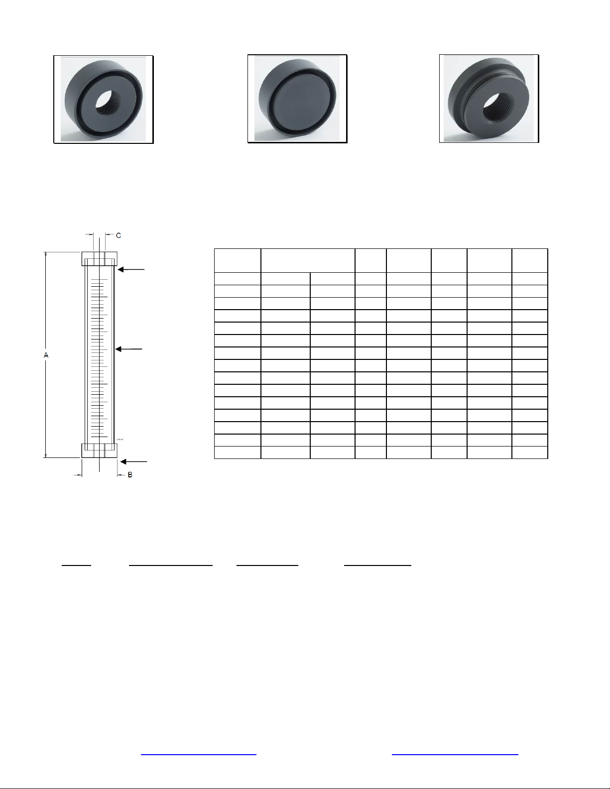
Description of models:
p
,
Sealed:
Top is glued to cylinder and contains a
vent or overflow connection. (FNPT).
Used in applications where there is a
positive suction head and a permanent
installation is desired.
Loose Cap: (Avail. up to 20,000 mL)
Top is loose and does not have a
connection in the top. Dust cover only.
Used in applications where there is no
positive suction head and the cylinder
must be filled from the top.
EZ-Clean: (Avail. 100 – 7000 mL
only)
Top is sealed with an O-ring and has a
vent connection, but removable for
easy cleaning. Used in applications
where frequent cleaning is required
such as polymer, alum, ferric chloride
or chlorine.
Top End
Ca
Clear PVC
Cylinder
Bottom
End Cap
Capacity
(mL) ◊
100
200
300
500
1,000
2,000
3,000
4,000
5,000
7,000
10,000
15,000
20,000
30,000
40,000
▲ Max Flow and gph scale are based on 30 second drawdown * Reference only
◊ For 60 sec draw down
Max Flow ▲
(USgph) (lph)
Scale
(mL)
Scale ▲
(gph)
A
(in)
3.17 12 1 .1 11 1.5 1/2
6.34 24 1 .1 19 1.5 1/2
9.51 36 5 .2 13 2.2 1/2
15.85 60 5 .2 13 2.5 3/4
31.70 120 5 .2 22 2.5 3/4
63.40 240 10 1 20 3.7 1
95.10 360 10 1 17 4.9 1 1/2
126.8 480 10 1 37 3.7 1
158.5 600 10 1 28 4.9 1 1/2
221.9 840 10 1 38 4.9 1 1/2
317.0 1200 100 5 25 6.95 2
475.5 1800 100 5 36 6.95 2
634.0 2400 100 5 47 6.95 2
952.0 3600 200 10 65* 9.5* 4
1,268.0 4800 200 10 77.5* 9.5* 4
double capacityin mL or flow size
Codes for Ordering PVC Calibration Cylinders:
B
(in)
C
(in)
CC □□□□ □ □ □
1 2 3 4
1 = Size 2 = Top End Cap Style 3 = Connections 4 = Oring Material
(Top Cap Only) (Union & EZ end cap orings)
0100 – 100 mL Blank – Sealed Blank – Threaded Blank – FKM (Viton
0200 – 200 mL L – Loose
0300 – 300 mL EZ – EZ Clean
0500 – 500 mL U – Union
1000 – 1000 mL
2000 – 2000 mL
3000 – 3000 mL
4000 – 4000 mL
5000 – 5000 mL
7000 – 7000 mL
10000 – 10000 mL
15000 – 15000 mL
20000 – 20000 mL
30000 – 30000 mL
40000 – 40000 mL
(up to 20000mL) S – Socket E - EPDM
(up to 7000mL) F – Flanged
(PTFE Encapsulated
or FFKM are available
upon request)
®
)
Website: www.griffcovalve.com email: sales@griffcovalve.com
 Loading...