

Grifco U-Drive GUDK-RSO-H053M, GUD-MK-07, GSB-600, U-Drive GUDK-RSO-H073M, GUD-H053M Instruction Manual
...
Chamberlain Australia Pty Ltd
PO Box 1446, Lane Cove
NSW 1595, Australia
Phone toll free 1800 474 326
D-M-RSO-040A 06/11/18
Chamberlain New Zealand Ltd
PO Box 100-221
North Shore 0745, New Zealand
Phone toll free 0800 653 667
THIS OPERATOR IS TO BE INSTALLED AND SERVICED BY A TRAINED TECHNICIAN ONLY
Compatible with GLMe2 eDrive +2.0 Wall Control
INSTRUCTION MANUAL
U-Drive
Operator for Non Spring-Balanced
Roller Shutters
www.grifco.com.au
www.grifco.co.nz
2
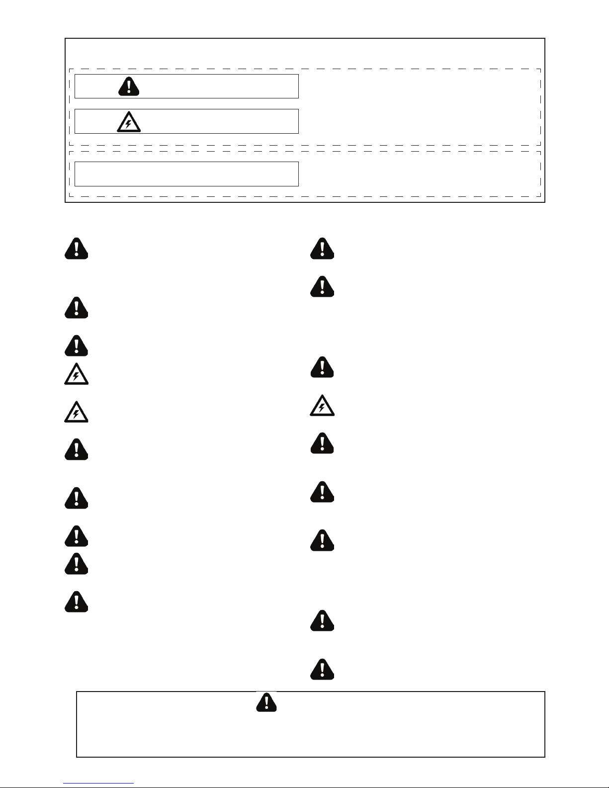
WARNING:
Important safety instructions
It is important for the safety of persons to follow all instructions.
SAVE these instructions
WARNING
CAUTION
WARNING
This commercial door operator has been designed and tested to offer safe service provided it is installed, operated, maintained and
tested in strict accordance with the instructions and warnings contained in this manual.
Mechanical
Electrical
When you see these Safety Symbols and Signal Words on the
following pages, they will alert you to the possibility of serious
injury or death if you do not comply with the warnings that
accompany them. The hazard may come from something
mechanical or from electric shock.
When you see this Signal Word on the following pages, it will
alert you to the possibility of damage to your commercial door
and/or the commercial door operator if you do not comply with
the cautionary statements that accompany it.
THESE ARE IMPORTANT SAFETY INSTRUCTIONS. FOLLOW ALL INSTRUCTIONS AS INCORRECT
INSTALLATION CAN LEAD TO SEVERE INJURY OR DEATH
Keep commercial door maintained. Sticking or binding
doors must be repaired. Commercial doors, brackets and
their hardware are under extreme tension and can cause
serious personal injury. Do not attempt to loosen, move or
adjust them. Call for commercial door service.
Where applicable, permanently fasten all supplied labels
adjacent to the wall control as a convenient reference and
reminder of safe operating procedures.
Disengage all existing commercial door locks to avoid
damage to commercial door. Install the control (or any
additional push buttons) in a location where the commercial
door is visible during operation . Do not allow children to
operate push button(s) or remote control(s). Serious personal
injury from a closing commercial door may result from misuse
of the opener.
Activate opener only when the door is in full view, free of
obstructions and opener is properly adjusted. No one should
enter or leave the building while the door is in motion.
An electrician must disconnect electric power to the
commercial door opener and control before making repairs or
removing covers.
The actuating member of a biased-off switch is to be located
within direct sight of the door but away from moving parts.
Unless it is key operated, it is to be installed at a minimum
height of 1500mm and not accessible to the public.
Make sure that people who install, maintain or operate the
door follow these instructions. Keep these instructions in a
safe place so that you can refer to them quickly when you
need to.
This appliance is not intended for use by persons (including
children) with reduced physical, sensory or mental
capabilities, or lack of experience and knowledge, unless
they have been given supervision or instruction concerning
use of the appliance by a person responsible for their safety.
Children should be supervised to ensure that they do not play
with the appliance.
If the opener is installed at a height less than 2.5 meters
from floor level or any other level from which the unit can
be accessed (eg mezzanine) the installer is responsible to fit
guards to the opener to prevent access to the chain drive.
Ensure that the temperature range marked on the operator is
suitable for the location. Ensure that entrapment due to the
opening movement of the of the driven part is avoided.
Unbalanced roller shutter doors require a Suitable AntiDrop device to catch the door in the event a a failure of
the drive system., such as the GRIFCO GSB-600.
Do not wear rings, watches or loose clothing while
installing or servicing a commercial door opener.
To avoid serious personal injury from entanglement,
remove all ropes connected to the commercial door
before installing the door control.
Installation and wiring must be in compliance with your
local building and electrical codes. Connect the power
supply cord only to properly earthed mains if applicable.
Moisture and water can destroy the electronic components.
Make sure under all circumstances that water moisture or
storage moisture cannot penetrate the electronics. The
same applies for openings and cable entries.
After the installation a final test of the full function of the
system and the full function of the safety devices must
be done.
When operating a biased-off switch, make sure that other
persons are kept away.
The opener cannot be used with a driven part
incorporating a wicket door (unless the opener cannot be
operated with the wicket door open).
Motor may become hot during operation. Appropriate
clearance and/or shielding should be supplied by the
installer to ensure any cabling, wiring and/or other items
cannot come in contact with the motor. If temperature
rise exceeds 50°C all fixed wiring insulation must be
protected, for example, by insulating sleeving having an
appropriate temperature rating.

3
SAFETY INSTRUCTIONS ............................................................................................. 2
TYPICAL INSTALLATION ............................................................................................. 4
SPECIFICATIONS ..................................................................................................... 5-9
Specifications Table ..................................................................................................................... 5
Dimensions ................................................................................................................................... 6
Contents .......................................................................................................................................7
Selection Guide ........................................................................................................................ 8-9
INSTALLATION ..................................................................................................... 10-17
Install Wall Brackets ...................................................................................................................10
Install Door Drum .......................................................................................................................10
Install Flange Bearing ................................................................................................................10
Install Safety Brake Angle .......................................................................................................... 11
Install Safety Brake ....................................................................................................................11
Select Mounting Configuration .................................................................................................. 12
Select In-Board or Out-Board Mounting Configuration ........................................................... 13
Install Operator Mounting Plate ................................................................................................13
Mount Operator to Wall Bracket ...............................................................................................14
Install Sprocket...........................................................................................................................14
Install Drive Chain ......................................................................................................................15
Electrical Installation ............................................................................................................ 16-17
COMMISSIONING ................................................................................................. 18-19
Setting Limits .............................................................................................................................. 18
Manual Setting of Door Position ...............................................................................................19
MAINTENANCE ......................................................................................................... 20
TROUBLESHOOTING ............................................................................................ 21-22
CHAMBERLAIN LIMITED WARRANTY ....................................................................... 24
TABLE OF CONTENTS
The U-Drive can be operated with a standard
GLMe2 Series controller, or one of our standard
reversing starters. The mechanical limit system
and high torque output make this an ideal solution
for high-cycle non spring-balanced roller shutters
and grilles.
This manual details the mechanical installation of
the U-Drive system and safety brake. For all other
electrical connections please refer to the
respective controller’s manual.
4
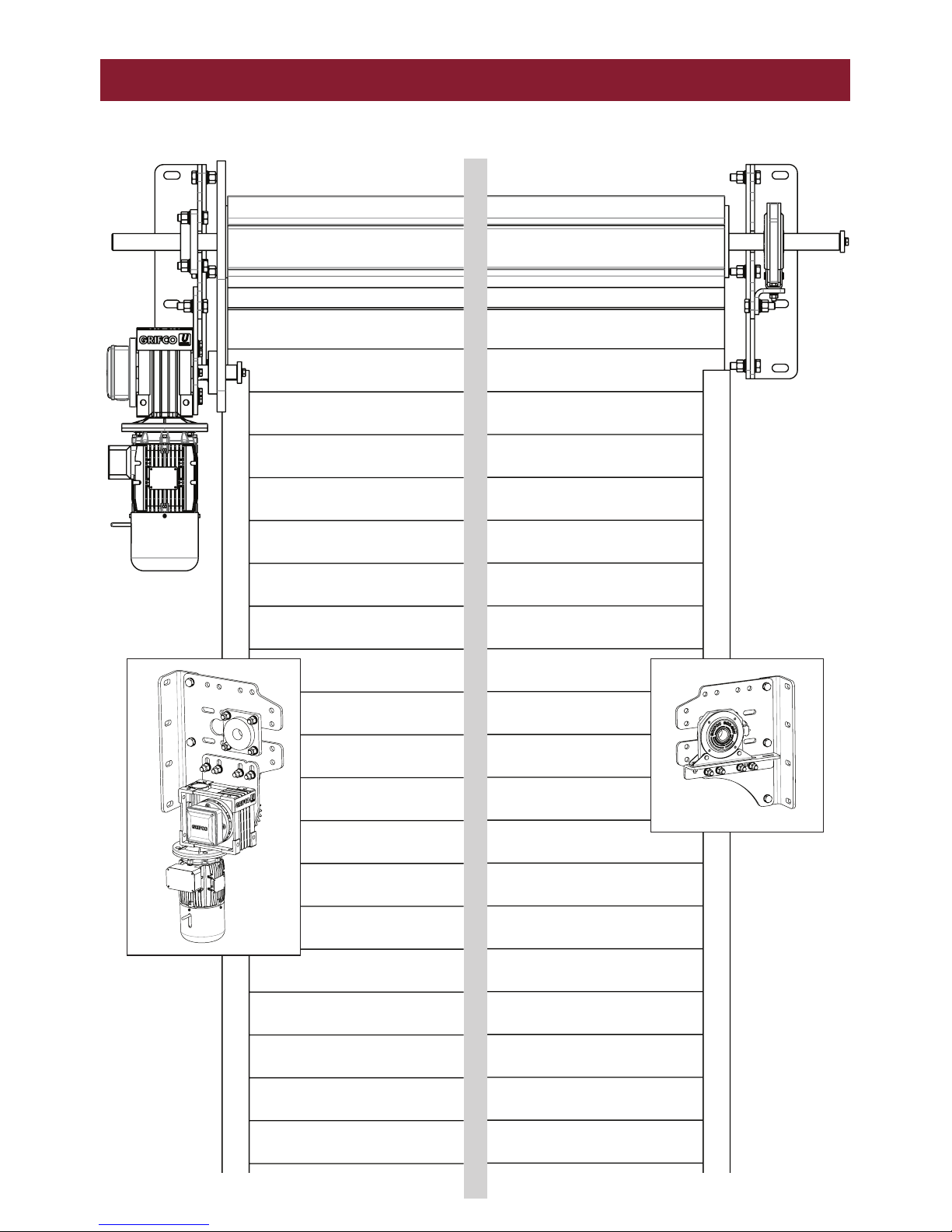
TYPICAL INSTALLATION
INSTALLATION OF GUDK-RSO-H073M SHOWN

5
SPECIFICATIONS
* Note: Door size indication only based on standard door weights and dimensions, it remains the
responsibility of the installer to confirm maximum drum torque and system mass before installation.
GUD-H053M
GUD-MK-05
GUD-H073M
GUD-MK-07
Peak Opener Torque 180 Nm 260 Nm
Peak Drum Torque 600 Nm 600 Nm
Max Bracket capacity (Pair) 574 kg 800 Kg
Power 0.5 Hp 0.75 Hp
Full Load Current 1.8 A 2 A
Volts (AC) 415 V 415V
Phase 3 3
Max safety brake speed 16 rpm 16 rpm
Output shaft speed 14 rpm 14 rpm
Limits 2 x N/C Micro Switch 2 x N/C Micro Switch
Rated Load 110N.m @ RUN TIME = 7.6min 183N.m @ RUN TIME = 10min
Drive Sprocket supplied 25T 12B 25T 12B
6
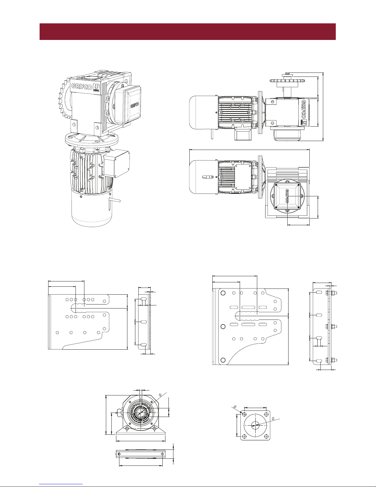
SPECIFICATIONS
GUD-H053M / GUD-H073M
GUD-MK-05
GSB-600 FLANGE BEARING
GUD-MK-07
554
104
104
322
130 99.5
180 MIN
180 320
292 MAX
120
10
150 150 150
70
20
180 MIN
180 320
292 MAX
120
10
150 150 150
70
20
180 MIN
90 270
236 MAX
150 150
20
35
80
8
110
200
250
40
12
43.3
220
46
40
19
112
112
40
19
112
112

7
SPECIFICATIONS
CONTENTS
GUD-H053M
A. Motor and gearbox assy with limits and output shaft
B. 25T sprocket
C. Operator mounting plate
D. Drive chain 12B (Not shown)
E. Operator fastener kit (Not shown)
F. Manual (Not shown)
GUD-H073M
A. Motor and gearbox assy with limits and output shaft
B. 25T sprocket
C. Operator mounting plate
D. Drive chain 12B (Not shown)
E. Operator fastener kit (Not shown)
F. Manual (Not shown)
GUDK-RSO-H073M - COMPLETE CONTENTS
GUDK-RSO-H053M - COMPLETE CONTENTS
GUD-MK-05
A. Wall bracket LH
B. Wall bracket RH
C. Safety brake angle
D. Flange bearing
E. Flange bearing fastener kit (Not shown)
F. Safety brake fastener kit (Not shown)
G. Wall bracket fastener kit (Not shown)
GSB-600
Safety Brake
GSB-600
Safety Brake
GUD-MK-07
A. Wall angle x 2
B. Wall bracket x 2
C. Safety brake angle
D. Flange Bearing
E. Flange Bearing Fastener kit (Not shown)
F. Safety Brake Fastener kit (Not shown)
G. Wall Bracket Fastener kit (Not shown)
A.
A.
B.
B.
C.
C.
C.
C.
A.
A.
B.
B.
D.
D.
8
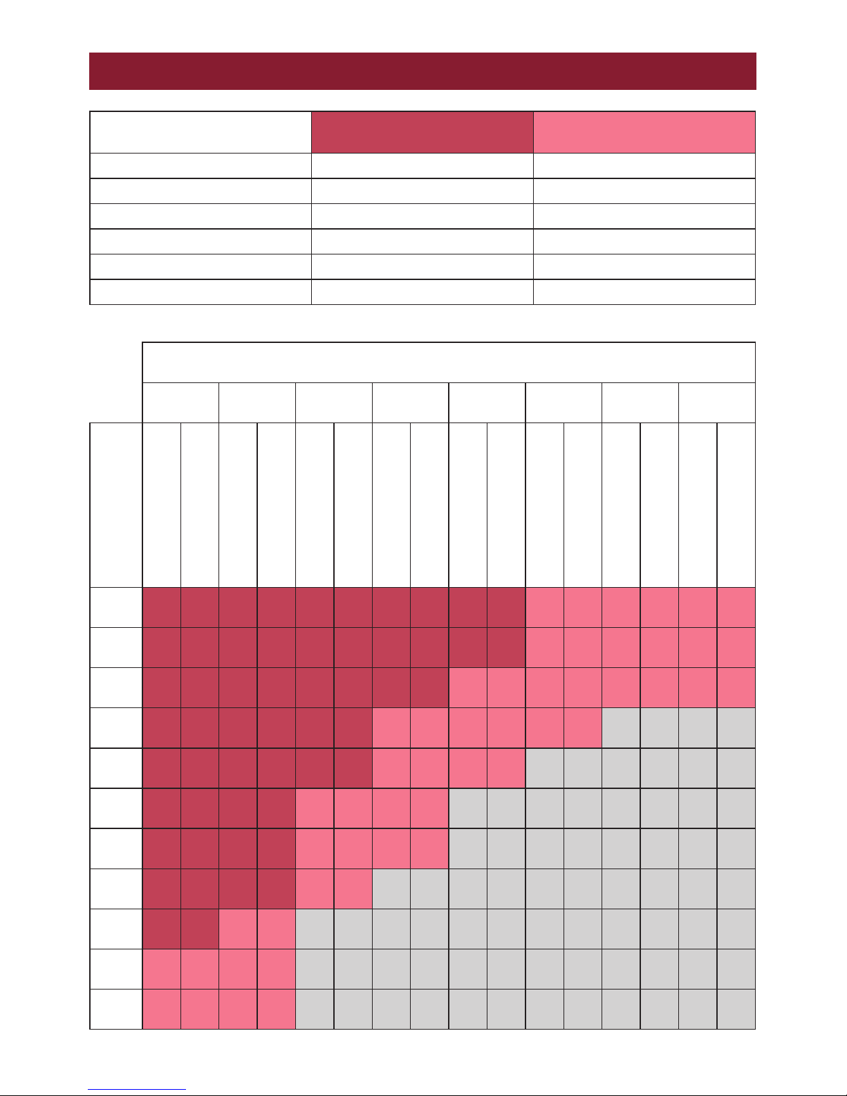
SELECTION GUIDE 60% DUTY
Door Height (Drum Axis to Floor)
2.5m 3m 3.5m 4m 4.5m 5m 5.5m 6m
Door Width
Drum Sprocket Teeth
Drum Speed Rpm
Drum Sprocket Teeth
Drum Speed Rpm
Drum Sprocket Teeth
Drum Speed Rpm
Drum Sprocket Teeth
Drum Speed Rpm
Drum Sprocket Teeth
Drum Speed Rpm
Drum Sprocket Teeth
Drum Speed Rpm
Drum Sprocket Teeth
Drum Speed Rpm
Drum Sprocket Teeth
Drum Speed Rpm
3m 35 10.0 35 10.0 35 10.0 35 10.0 35 10.0 35 10.0 36 9.7 40 8.8
3.5m 35 10.0 35 10.0 35 10.0 35 10.0 40 8.8 37 9.5 42 8.3 46 7.6
4m 35 10.0 35 10.0 35 10.0 40 8.8 37 9.5 42 8.3 47 7.4 54 6.5
4.5m 35 10.0 35 10.0 40 8.8 37 9.5 42 8.3 47 7.4 N/A N/A N/A N/A
5m 35 10.0 38 9.2 44 8.0 41 8.5 46 7.6 N/A N/A N/A N/A N/A N/A
5.5m 35 10.0 41 8.5 39 9.0 45 7.8 N/A N/A N/A N/A N/A N/A N/A N/A
6m 38 9.2 45 7.8 43 8.1 50 7.0 N/A N/A N/A N/A N/A N/A N/A N/A
6.5m 41 8.5 50 7.0 46 7.6 N/A N/A N/A N/A N/A N/A N/A N/A N/A N/A
7m 44 8.0 43 8.1 N/A N/A N/A N/A N/A N/A N/A N/A N/A N/A N/A N/A
7.5m 38 9.2 46 7.6 N/A N/A N/A N/A N/A N/A N/A N/A N/A N/A N/A N/A
8m 41 8.5 50 7.0 N/A N/A N/A N/A N/A N/A N/A N/A N/A N/A N/A N/A
60% DUTY GUD-H053M
GUD-MK-05
GUD-H073M
GUD-MK-07
Drum Diameter 168 mm 168 mm
Curtain Mass 14 kg/m2 14 kg/m2
Max System Mass 574 KG 800 KG
Max Door Size 20 m2 24 m2
Max Torque 180 Nm 220 Nm
Max Cycle Time 60s 60s
 Loading...