

Grifco GSD-SDO, GSD-R2.4M, GSD-R3.6M, GSD-RKIT Instruction Manual
Model GSD-SDO
Chamberlain Australia Pty Ltd
Unit 1, 75 Epping Rd North Ryde NSW 2113
Ph: 1800 638 234
www.grifco.com.au
Ref: 01-38727D
• THIS OPERATOR IS TO BE INSTALLED AND SERVICED BY A TRAINED TECHNICIAN ONLY
• This operator is compatible with Security+ 2.0® accessories
OPERATOR
REQUIRES GRIFCO
MONITORED ENTRAPMENT
PROTECTION
OPERATOR
REQUIRES GRIFCO
MONITORED ENTRAPMENT
PROTECTION
Commercial Sectional Door Operator
With Integral Battery Back Up
GSD-SDO
DC Operator
GSD-R2.4M
Rail for 2.4m Door
GSD-R3.6M
Rail for 3.6m Door
GSD-RKIT
Hardware Kit for
Custom Rail Length
up to 6m
INSTRUCTION MANUAL
2
WARNING:
Important safety instructions
It is important for the safety of persons to follow all instructions.
SAVE these instructions
WARNING
CAUTION
WARNING
This commercial door operator has been designed and tested to offer safe service provided it is installed, operated, maintained and tested
in strict accordance with the instructions and warnings contained in this manual.
Mechanical
Electrical
When you see these Safety Symbols and Signal Words on the
following pages, they will alert you to the possibility of serious
injury or death if you do not comply with the warnings that
accompany them. The hazard may come from something
mechanical or from electric shock.
When you see this Signal Word on the following pages, it will alert
you to the possibility of damage to your commercial door and/or
the commercial door operator if you do not comply with the
cautionary statements that accompany it.
Keep commercial door balanced. Sticking or binding doors must be
repaired. Commercial doors, door springs, pulleys, brackets and their
hardware are under extreme tension and can cause serious personal
injury. Do not attempt to loosen, move or adjust them. Call for commercial
door service.
Permanently fasten all supplied labels adjacent to the wall control as a
convenient reference and reminder of safe operating procedures.
Activate operator only when the door is in full view, free of obstructions
and operator is properly adjusted. No one should enter or leave the
building while the door is in motion.
An electrician must disconnect electric power to the commercial door
operator before making repairs or removing covers.
The actuating member of a biased-off switch is to be located within direct
sight of the door but away from moving parts. Unless it is key operated, it
is to be installed at a minimum height of 1500mm and not accessible to
the public.
Make sure that people who install, maintain or operate the door follow
these instructions. Keep these instructions in a safe place so that you can
refer to them quickly when you need to.
This appliance is not intended for use by persons (including children) with
reduced physical, sensory or mental capabilities, or lack of experience and
knowledge, unless they have been given supervision or instruction
concerning use of the appliance by a person responsible for their safety.
Children should be supervised to ensure that they do not play with the
appliance.
If the operator is installed at a height less than 2.5 metres from floor level
or any other level from which the operator can be accessed (eg
mezzanine) the installer is responsible to fit guards to the operator to
prevent access to the chain drive.
Use the commercial door operator for its intended purpose. The GSDSDO S-Drive operator is designed lifting spring-balanced sectional doors.
Disengage all existing commercial door locks to avoid damage to
commercial door. Install the wall control (or any additional push buttons) in
a location where the commercial door is visible during operation . Do not
allow children to operate push button(s) or remote transmitter(s). Serious
personal injury from a closing commercial door may result from misuse of
the operator.
Do not wear rings, watches or loose clothing while installing or servicing a
commercial door operator.
To avoid serious personal injury from entanglement, remove all ropes
connected to the commercial door before installing the door operator.
After the installation a final test of the full function of the system and the
full function of the safety devices must be done.
When operating a biased-off switch, make sure that other persons are
kept away.
The operator cannot be used with a driven part incorporating a wicket
door (unless the operator cannot be operated with the wicket door open).
Motor may become hot during operation. Appropriate clearance and/or
shielding should be supplied by the installer to ensure any cabling, wiring
and/or other items cannot come in contact with the motor. If temperature
rise exceeds 50°C all fixed wiring insulation must be protected, for
example, by insulating sleeving having an appropriate temperature rating.
THESE ARE IMPORTANT SAFETY INSTRUCTIONS. FOLLOW ALL INSTRUCTIONS AS INCORRECT
INSTALLATION CAN LEAD TO SEVERE INJURY OR DEATH
Installation and wiring must be in compliance with your local building and
electrical codes. Connect the power supply cord only to properly earthed
mains. If the supply cord is damaged, it must be replaced by the
manufacturer, its service agent or similarly qualified persons in order to
avoid a hazard.
Moisture and water can destroy the electronic components. Make sure
under all circumstances that water moisture or storage moisture cannot
penetrate the electronics. The same applies for openings and cable
entries.
SAFETY SYMBOL AND SIGNAL WORD REVIEW
3
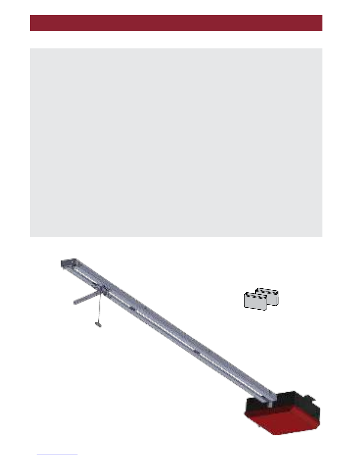
CARTON INVENTORY
GSD-SDO DC Operator
GSD-R2.4M 2.4 m Rail
GSD-R3.6M 3.6 m Rail
GSD-RKIT Rail Kit for Custom Length
(6m max)
Battery 12 Vdc 7AH (2)
INTRODUCTION
CONTENTS
NOT SHOWN:
Door Bracket
J-Bar
Fasteners
Documentation Packet
Chain
SAFETY
SAFETY SYMBOL AND SIGNAL WORD REVIEW ..................... 2
INTRODUCTION 3
CARTON INVENTORY ................................................................ 3
OPERATOR SPECIFICATIONS ................................................... 4
OPERATOR OVERVIEW ............................................................. 5
CONTROL BOARD OVERVIEW .................................................. 6
EXPANSION BOARD OVERVIEW ............................................... 7
INSTALLATION 8
CONNECT RAIL TO OPERATOR ............................................... 8
MOUNT THE OPERATOR .......................................................... 8
ELECTRICAL CONNECTION AND DOOR ATTACHMENT .......... 9
CONNECT BATTERIES .............................................................. 9
DISCONNECT BATTERIES ......................................................... 9
COMMISSIONING 10
LIMIT SETTING......................................................................... 10
TYPES OF MONITORED ENTRAPMENT PROTECTION ........... 11
SELECTION OF ENTRAPMENT PROTECTION SYSTEM ......... 11
COMMISSIONING ENTRAPMENT PROTECTION SYSTEMS ... 12
FORCE SETTING AND FINE ADJUSTMENT............................. 13
TYPES OF SECURITY +2.0 TRANSMITTERS ........................... 14
COMMISSIONING REMOTE TRANSMITTERS ......................... 15
ACCESSORY WIRING ............................................................ 17
CONNECTING ACCESS CONTROL ACCESSORIES ............... 17
CONNECTING EXTERNAL CONTROL DEVICES ...................... 17
MISECLLANEOUS WIRING ...................................................... 18
OPERATION 18
RESET BUTTON ...................................................................... 18
OPERATOR ALARM ................................................................. 19
MANUAL DISCONNECT........................................................... 19
EXPANSION BOARD 20
AUXILIARY RELAYS ................................................................. 20
WIRING ACCESSORIES TO THE EXPANSION BOARD ........... 21
MAINTENANCE 22
MAINTENANCE CHART ........................................................... 22
BATTERY MAINTENANCE ....................................................... 22
TROUBLESHOOTING 23
VIEWING DIAGNOSTIC CODES ............................................... 23
DIAGNOSTIC CODES CHART .................................................. 25
CONTROL BOARD LEDS ......................................................... 27
TROUBLESHOOTING CHART .................................................. 28
SERVICE AND REPAIR PARTS ................................................ 30
WIRING DIAGRAM 31
CHAMBERLAIN LIMITED WARRANTY 32
4
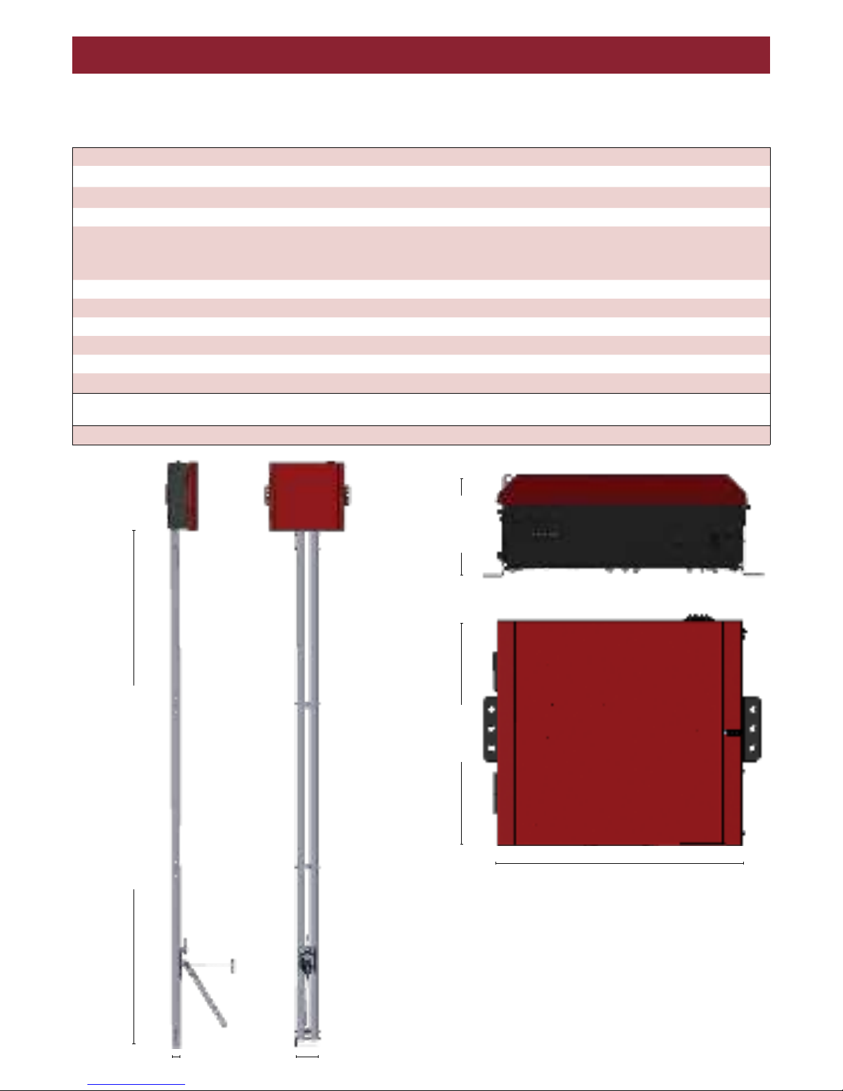
OPERATOR SPECIFICATIONS
Main AC Power Supply 230-240 VAC 50Hz, 400W
Rated Load (R/T) 270N (Continuous)
System Operating Voltage 24 VDC Transformer Run / Battery Backup
Accessory Power 24 VDC, 500 mA max. for ON and SW (switched)
Maximum Door Heights (Rail Part No.) 2.4m (GSD-R2.4M)
3.6m (GSD-R3.6M)
6.0m (GSD-RKIT - rail angle not supplied)
Maximum Door Weight 315.5 kg balanced door
Maximum Door Area 26m²
Travel Speed 20cm per second
Maximum Duty Cycle Continuous
Operating Temperature +5°C to +40°C
Expansion Board Included
Compliance AS/NZS 60335-1
AS/NZS 60335-2-103
Usage Indoor Use Only
INTRODUCTION
2.4 m Rail GSD-R2.4M: 3,380 mm
3.6 m Rail GSD-R3.6M : 4,580 mm
146 mm
490 mm
445 mm 200 mm
50 mm
5
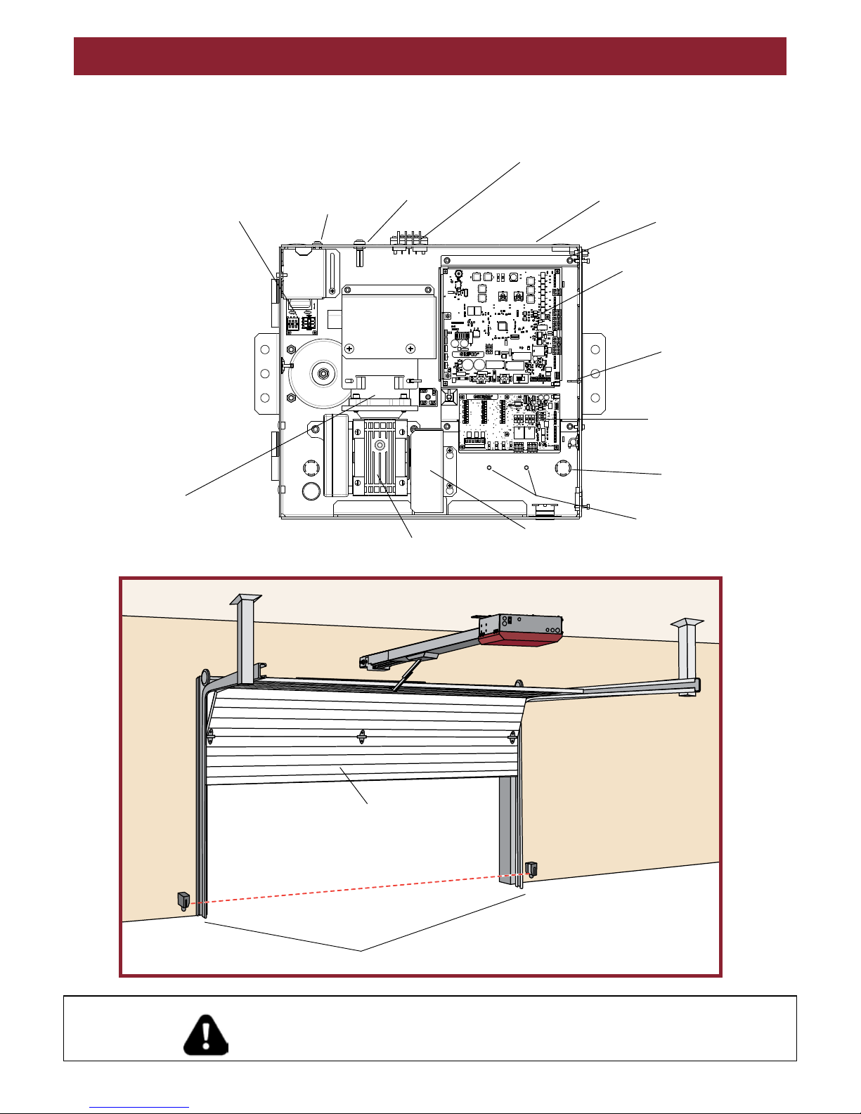
EXPANSION
BOARD
CONDUIT ENTRY /
EXIT TOP OF
OPERATOR
GSD-STAR1000EVO
MOUNTING
(NOT INCLUDED)
LOCKABLE LID
CHAIN GUARD
MOTOR
GEAR BOX
CONTROL BOARD
CONDUIT ENTRY / EXIT
REAR OF OPERATOR
ANTENNA CONNECTION
RESET BUTTON
ACCESS CONTROL DEVICE
EXTERNAL TERMINAL BLOCK
AC POWER
SWITCH
EMI BOARD
INTRODUCTION
PE Beams (Sold Separately)
Make sure the door opens and closes smoothly.
Door should stay in the open position when
springs are properly balanced.
WARNING
Always wear protective gloves and eye protection when changing
the battery or working around the battery compartment.
OPERATOR OVERVIEW
6
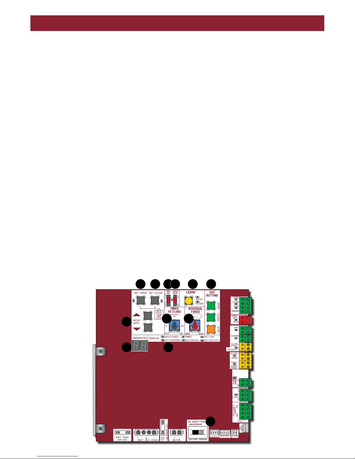
CONTROL BOARD OVERVIEW
1. SET OPEN Button: The SET OPEN button sets the OPEN limit. See Adjust Limits section
2. SET CLOSE Button: The SET CLOSE button sets the CLOSE limit. See Adjust Limits section.
3. MOVE GATE Buttons: The MOVE GATE buttons will either open or close the door when the operator is in Limit setting mode.
See Adjust Limits section
4. BATT FAIL:
• When AC power is OFF and battery voltage is critically low the door will latch at a limit until AC power is restored or Batteries
voltage increases
• Option select switch set to OPEN forces door to automatically open and then latch at the OPEN limit until AC power is restored or
battery voltage increases
• Option select switch set to CLOSE forces door to latch at CLOSE limit if at CLOSE limit or on next CLOSE Command until AC
power restored or battery voltage increases
• Constant pressure on a hard command input overrides to open or close the gate/door
• Critically low battery is less than 23V
5. BIPART DELAY Switch: Not used in this application, ensure switch remains in OFF position
6. LEARN Button: The LEARN button is for programming remote transmitters and the network.
7. TIMER-TO-CLOSE dial: The TIMER-TO-CLOSE (TTC) dial can be set to automatically close the door after a specified time period.
The TTC is factory set to OFF. If the TTC is set to the OFF position, then the door will remain open until the operator receives another
command from a control. Rotate the TIMER-TO-CLOSE dial to the desired setting. The range is 0 to 180 seconds, 0 seconds is OFF
NOTE: Any radio command, single button control, or CLOSE command on the control board prior to the TTC expiring will close the
door. The TTC is reset by any signals from the open controls, loops, close edges, and close photoelectric sensors (IR’s)
8. REVERSAL FORCE dial: The REVERSAL FORCE dial adjusts the force. See Force Adjustment section
9. TEST BUTTONS: The TEST BUTTONS will operate the door (OPEN, STOP and CLOSE)
10. STATUS LEDs: The STATUS LEDs indicate the status of the operator. See Status LED Chart in the Troubleshooting section
11. Diagnostic Code Display: The diagnostic code display will show the operator type, firmware version, and diagnostic codes. The
operator type will display as "Gd" followed by a "24" which indicates the operator type as GSD-SDO. The firmware version will show
after the operator type, example "1.2"
12. BACKDRIVE Switch: MUST BE set to SECURE
1 2 4 5 6
7 8
9
10
12
11
3
INTRODUCTION
7
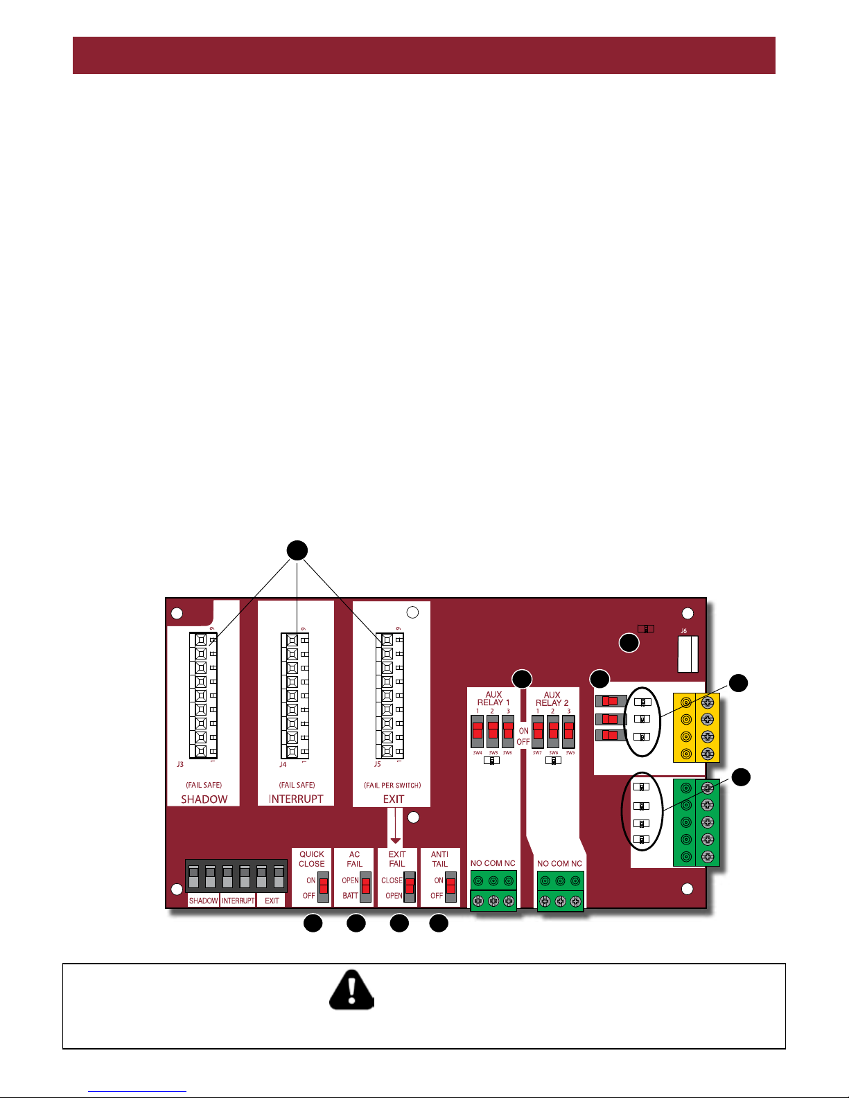
EXPANSION BOARD OVERVIEW
SBC
OPN
CLS
STP
COM
EYE
ONLY
EYE/
EDGE
EYE/
EDGE
COM
1
2
3
OPEN
CLOSE
TO MAIN
BOARD
POWER
10
1 2 3 4
5 6
7
9
8
1 QUICK CLOSE Switch:
OFF: No change to the door's normal operation.
ON: When CLOSE EYES/Interrupt loop is deactivated it causes
an opening or a stopped door to close (ignores the Timer-to Close).
2 AC FAIL Switch:
OPEN: Loss of AC power will cause the door to open
approximately 15 seconds after AC power fail and remain OPEN
until AC power is restored (enabling the Timer-to-Close).
BATT: With loss of AC power, door will remain in present position
and operator is powered from batteries.
3 EXIT LOOP FAIL Switch:
OPEN: if the EXIT plug-in loop detector detects a fault, then
the door will open and remain open until fault is cleared.
CLOSE: The plug-in EXIT loop detector faults are ignored (EXIT
loop is faulted and inoperative
4 ANTI-TAIL Switch:
OFF: When CLOSE EYES/Interrupt loop is activated it causes a
closing door to stop and reverse.
ON: When CLOSE EYES/Interrupt loop is activated it causes a
closing door to pause. Once the vehicle is clear the door will
continue to close.
5 AUX RELAY Switches: Set the AUX RELAY switches as need-
ed to obtain the desired function as shown on pages 20-21.
6 EYE/EDGE Switches: Set the EYE/EDGE switches as needed
to obtain the desired OPEN or CLOSE functionality.
7 1, 2, and 3 LEDs: LEDs indicating the status of the EYE/EDGE
inputs. Also used to check the firmware version of the expansion
board:
1. Locate the 1, 2, and 3 LEDs on the expansion board.
2. Disconnect AC/DC power to the main control board for 15
seconds.
3. Connect power. The 1, 2, and 3 LEDs will flash in sequence
until the main control board firmware revision is displayed.
When the green POWER LED glows solid the LED 1 will flash
the version number, then stop, then the LED 2 will flash the
revision number (for example: For version 5.1 when the green
POWER LED is solid the LED 1 will flash 5 times, then stop,
then the LED 2 will flash once).
8 MAIN BOARD Input: Input Connection for the main board
connector.
9 Input LEDs: LEDs indicating the status of the SBC, OPN, CLS,
and STP inputs.
10 Loop Detector Inputs: Inputs for the Plug-In Loop Detectors
WARNING
To AVOID damaging the circuit board, relays or accessories, DO NOT connect more than 42 Vdc (32 Vac) to the
AUX relay contact terminal blocks.
INTRODUCTION
8
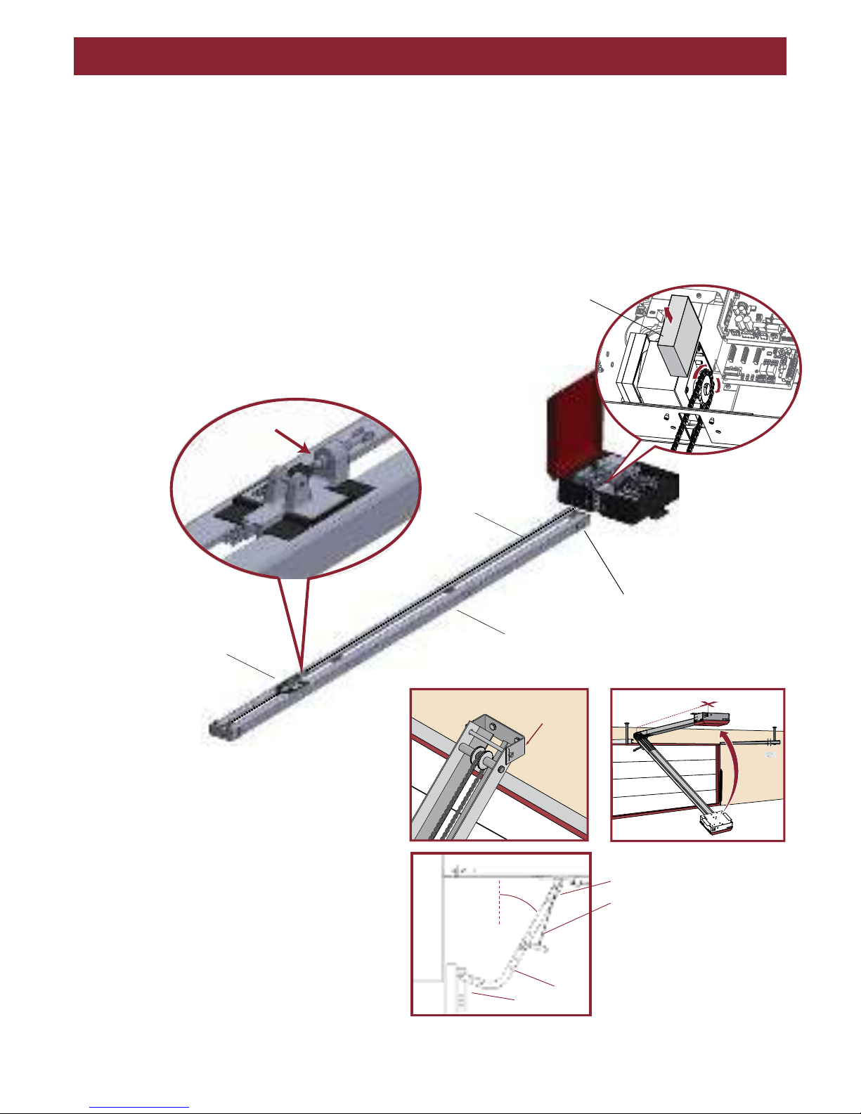
Chain Guard
Trolley
Rail
Chain
STEP 1
CONNECT RAIL TO OPERATOR
BEFORE INSTALLATION, ENSURE THE OPERATOR IS SUITABLE FOR THE TYPE AND SIZE OF THE DOOR. ENSURE THE
TEMPERATURE RANGE MARKED ON THE OPERATOR IS SUITABLE FOR THE LOCATION OF THE INSTALLATION.
ENSURE THAT THE DRIVEN PART IS IN GOOD MECHANICAL CONDITION, CORRECTLY BALANCED
AND OPENS AND CLOSES PROPERLY.
INSTALLATION
1
2/7
4
6
3
5
STEP 2
MOUNT THE OPERATOR
1. With the door closed, mark the centre of the door on the
wall above the door
2. Open the door and mark the centre of the door on the
ceiling. Ensure height of the rail has the correct clearance
with the door in the open position (see diagram right)
3. Close the door, mount the header bracket and rail
assembly to the wall. Make sure the header bracket is in
the centre of the door opening
4. Lift the operator and align with the centre mark on the
ceiling. Temporarily support the operator
5. Attach operator to ceiling using lateral mounting brackets.
Ensure at least 1 fixing on either side of the operator
6. Attach the door bracket to the door
7. Attach the push arm to the trolley, test emergency release
rope is operational. Attach the J-bar to the push arm
8. Attached J-bar to door bracket after following STEP 3 on
the next page
Header Bracket
J-bar
20°
Door Bracket
Push Arm
NOTE: U-shape bracket
with square holes
indicates the end of the
rail that connects to
the operator.
Emergency Release Rope
NOTE: Trolley can not be
moved independantly of chain.
For attaching the J-bar to the
door bracket, trolley needs to
be positioned by using the
operator. Follos STEP 3 on the
next page.
NOTE: Lateral mounting plates are provided with multiple holes.
Alternate holes to the installation can be used to temporarily suspend
the operator (with ropes, hooks etc not provided) during mounting.
1. Position the operator and rail as shown below
2. Open the cover and remove the chain guard
3. Secure the rail to the operator with the square-neck bolts and Nylock nuts provided.
NOTE - Do not use washers with these nuts
4. Cut the cable ties securing the chain
(The trolley should be approximately 1m from the end of the rail)
5. Remove tensioner nut (shown as (6) below) and wrap the chain around the
output sprocket
6. Reconnect the tensioner nut and tighten until chain hangs approx 10mm
below horizontal
7. Replace chain guard
9
STEP 3
ELECTRICAL CONNECTION AND DOOR ATTACHMENT
STEP 4
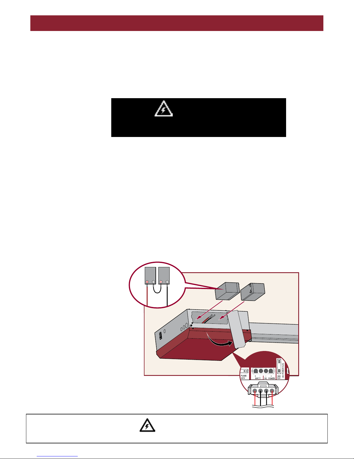
CONNECT BATTERIES
DISCONNECTING BATTERIES
Connect the operator to the mains power supply using the pre-connected mains plug to a 10A general power outlet
NOTE: After electrical connection, J-bar can be attached to door bracket by activating the operator. Press the "MOVE
GATE" buttons to position the trolley / J-bar assembly so it can be attached to the door bracket. Push arm should be
approx 20° from vertical
The batteries are charged in the circuit by the integrated transformer. The batteries are for battery backup
1. SEE WARNING! Unplug the J15 plug labelled BATT on the control board by squeezing the plug and pulling it from the control
board. This disconnects the ac/dc power to the control board
2. Loosen the screws on the battery cover and rotate out of the way
3. Connect the red wire to the positive (+) terminal on one battery and connect the black wire to the negative (-) terminal
on the other battery
4. Connect the black jumper (included with the batteries) between the positive (+) terminal of one battery to the
negative (-) terminal of the other battery
5. Insert the batteries as shown
6. Reattach the battery cover
7. Insert the J15 plug back into the control board. This will power up the control board. NOTE: You may see a
small spark when plugging the J15 plug into the board
8. Turn ON AC power at the wall switch
9. Turn ON the AC power switch on the rear of the operator
1. Turn OFF the AC power switch on the rear of
the operator
2. Turn OFF the power at the wall switch
3. SEE WARNING Remove the J15 plug from the
control board
4. Loosen the screws on the battery cover and
rotate out of the way
5. Carefully remove batteries and disconnect all
wires from the battery terminals
6. Dispose of used batteries responsibly
7. Follow instructions above to connect new
batteries
OPERATOR WILL NOT FUNCTION WITHOUT
GRIFCO BATTERIES CONNECTED
INSTALLATION
Black jumper
provided with
batteries
Black Wire (-)
Red Wire (+)
J15 Plug
1/7
9
2/6
3
4
5
WARNING
Batteries are supplied charged. When batteries are connected the operator is fully functional without AC power connected.
NOTE: Batteries are supplied fully charged.
They are automatically charged when
operator is connected to mains power.
WARNING
FAILURE TO DISCONNECT J15 PLUG LABELLED BATT WILL RESULT
IN POTENTIAL SHOCK HAZARD (FOLLOW STEP 4, POINT 1)
10
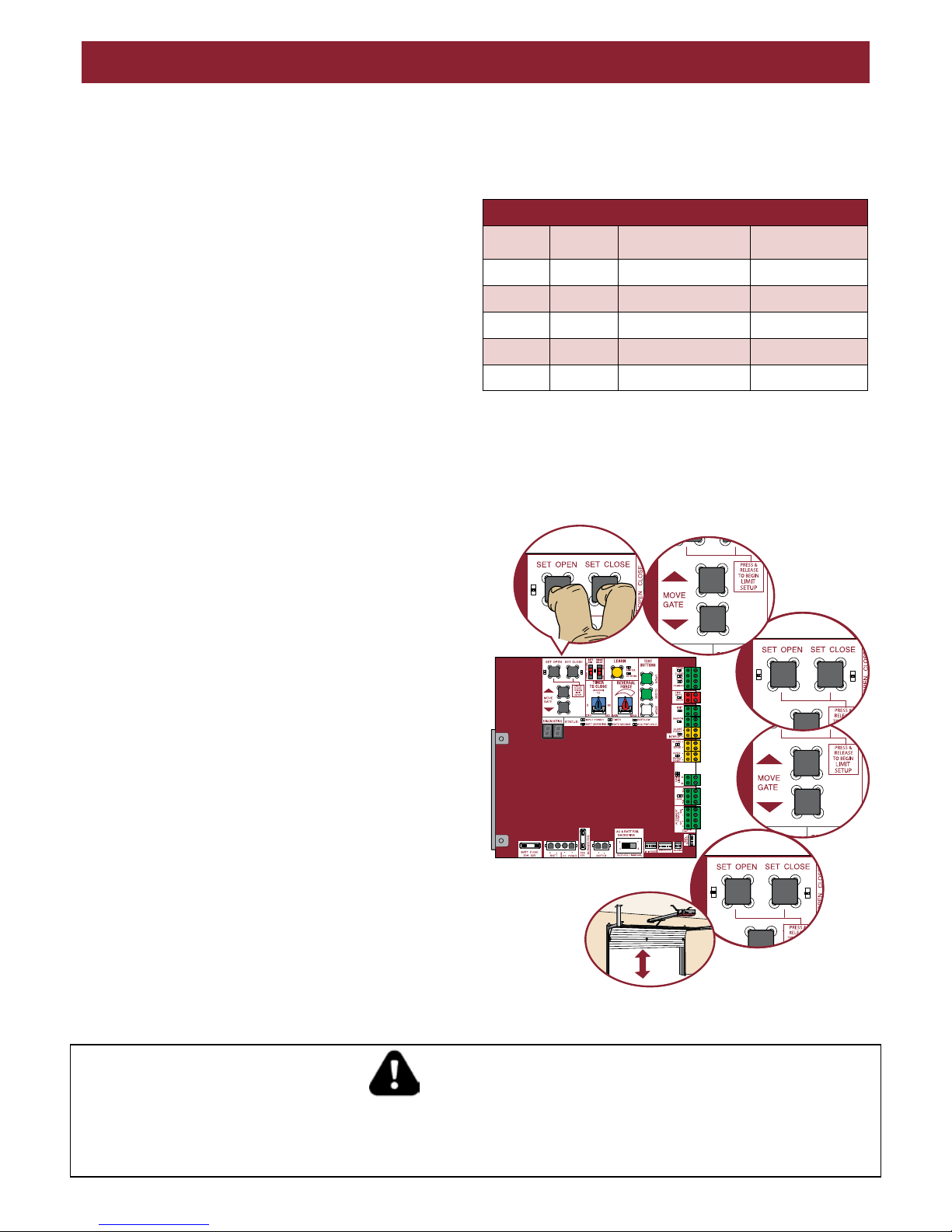
The door MUST be attached to the operator before setting the limits
and force.
1. Press and release the SET OPEN and SET CLOSE buttons
simultaneously to enter limit setting mode
2. Press and hold one of the MOVE GATE buttons to move the
door to the open or close limit
3. Press and release the SET CLOSE or SET OPEN button
depending on which limit is being set
4. Press and hold one of the MOVE GATE button to move the door
to the other limit
5. Press and release the SET CLOSE or SET OPEN button
depending on which limit is being set
6. Cycle the door open and close by pressing the green "TEST
BUTTONS" (Open and Close). This automatically sets the force
When limits are set properly the operator will automatically exit limit
setting mode.
INTRODUCTION
Your operator is designed with electronic controls to make travel
limit and force adjustments easy. The adjustments allow you to
program where the door will stop in the open and close position.
The electronic controls sense the amount of force required to open
and close the door.
The force is adjusted automatically when you program the limits but
can be fine tuned using the REVERSAL FORCE dial on the control
board (refer to Fine Tune the Force section) to compensate for
environmental changes.
The limit setup LEDs (located next to the SET OPEN and SET
CLOSE buttons) indicate the status of the limits, refer to
the table below.
LIMIT SETTING
LIMIT SETUP LEDS
SET OPEN
LED
SET CLOSE
LED
OPERATOR MODE EXPLANATION
OFF OFF NORMAL MODE Limits are set
BLINKING BLINKING LIMIT SETTING MODE Limits are not set
BLINKING ON LIMIT SETTING MODE Open limit is not set
ON BLINKING LIMIT SETTING MODE Close limit is not set
ON ON LIMIT SETTING MODE Limits are set
1
2
3
4
5
WARNING
• NEVER increase force beyond minimum amount required to
move door.
• NEVER use force adjustments to compensate for a binding or
sticking door.
• If one control (force or travel limits) is adjusted, the other control
may also need adjustment.
The limits can be set using the control board (below) or a remote transmitter (refer to Limit Setup with a Remote Transmitter in the
Programming section). Setting the limits with a remote transmitter requires a 3-button transmitter programmed to OPEN, CLOSE, and STOP.
NOTE: The Test Buttons on the control board will not work until the limits have been set.
COMMISSIONING
 Loading...