

Grifco Gld-sdo User Manual

OPERATOR
SUPPLIED WITH GRIFCO
MONITORED ENTRAPMENT
PROTECTION
OPERATOR
SUPPLIED WITH GRIFCO
MONITORED ENTRAPMENT
PROTECTION
INSTRUCTION MANUAL
LS-Drive
GLD-SDO
LS-Drive Operator
GLD-R2.4M
Rail for (max) 2.4m High Door
GLD-R3.0M
Rail for (max) 3.0m High Door
Model GLD-SDO
Commercial Sectional Door Operator
• THIS OPERATOR IS TO BE INSTALLED AND SERVICED BY A TRAINED TECHNICIAN ONLY
• This operator is compatible with Security+ 2.0® accessories
Chamberlain Australia Pty Ltd
Unit 1, 75 Epping Rd North Ryde NSW 2113
Ph: 1800 GRIFCO
www.grifco.com.au
Ref: 114A4934B
SAFETY SYMBOL AND SIGNAL WORD REVIEW
This commercial sectional door operator has been designed and tested to offer safe service provided it is installed, operated, maintained
and tested in strict accordance with the instructions and warnings contained in this manual.
WARNING
When you see these Safety Symbols and Signal Words on the
following pages, they will alert you to the possibility of serious
Mechanical
WARNING
injury or death if you do not comply with the warnings that
accompany them. The hazard may come from something
mechanical or from electric shock.
Electrical
When you see this Signal Word on the following pages, it will alert
CAUTION
you to the possibility of damage to your commercial door and/or
the commercial door operator if you do not comply with the
cautionary statements that accompany it.
THESE ARE IMPORTANT SAFETY INSTRUCTIONS. FOLLOW ALL INSTRUCTIONS AS INCORRECT
INSTALLATION CAN LEAD TO SEVERE INJURY OR DEATH
Keep commercial door balanced. Sticking or binding doors must be
repaired. Commercial doors, door springs, pulleys, brackets and their
hardware are under extreme tension and can cause serious personal
injury. Do not attempt to loosen, move or adjust them. Call for commercial
door service.
Do not wear rings, watches or loose clothing while installing or servicing a
commercial door operator.
To avoid serious personal injury from entanglement, remove all ropes
connected to the commercial door before installing the door operator.
Installation and wiring must be in compliance with your local building and
electrical codes. Connect the power supply cord only to properly earthed
mains.
Permanently fasten all supplied labels adjacent to the wall control as a
convenient reference and reminder of safe operating procedures.
Disengage all existing commercial door locks to avoid damage to
commercial door. Install the wall control (or any additional push buttons) in
a location where the commercial door is visible during operation . Do not
allow children to operate push button(s) or remote transmitter(s). Serious
personal injury from a closing commercial door may result from misuse of
the operator.
Activate operator only when the door is in full view, free of obstructions
and operator is properly adjusted. No one should enter or leave the
building while the door is in motion.
An electrician must disconnect electric power to the commercial door
operator before making repairs or removing covers.
Moisture and water can destroy the electronic components. Make sure
under all circumstances that water moisture or storage moisture cannot
penetrate the electronics. The same applies for openings and cable
entries.
After the installation a final test of the full function of the system and the
full function of the safety devices must be done.
When operating a biased-off switch, make sure that other persons are
kept away.
The operator cannot be used with a driven part incorporating a wicket
door (unless the operator cannot be operated with the wicket door open).
Motor may become hot during operation. Appropriate clearance and/or
shielding should be supplied by the installer to ensure any cabling, wiring
and/or other items cannot come in contact with the motor. If temperature
rise exceeds 50°C all fixed wiring insulation must be protected, for
example, by insulating sleeving having an appropriate temperature rating.
If the supply cord is damaged, it must be replaced by the manufacturer,
its service agent or similarly qualified persons in order to avoid a hazard.
Do not allow children to play with operator wall controls or remote
controls. Keep remote controls away from children.
WARNING: Important safety instructions
It is important for the safety of persons to follow all instructions.
SAVE these instructions
The actuating member of a biased-off switch is to be located within direct
sight of the door but away from moving parts. Unless it is key operated, it
is to be installed at a minimum height of 1500mm and not accessible to
the public.
Make sure that people who install, maintain or operate the door follow
these instructions. Keep these instructions in a safe place so that you can
refer to them quickly when you need to.
This appliance is not intended for use by persons (including children) with
reduced physical, sensory or mental capabilities, or lack of experience and
knowledge, unless they have been given supervision or instruction
concerning use of the appliance by a person responsible for their safety.
Children should be supervised to ensure that they do not play with the
appliance.
Use the commercial sectional door operator for its intended purpose. The
GLD-SDO operator is designed lifting spring-balanced sectional doors.
2

INTRODUCTION
CONTENTS
SAFETY SYMBOL AND SIGNAL WORD REVIEW .........................................................................................................2
INTRODUCTION ..............................................................................................................................................................3
OPERATOR SPECIFICATIONS ...............................................................................................................................................................4
OPERATOR OVERVIEW .........................................................................................................................................................................5
CONTROL PANEL OVERVIEW ...............................................................................................................................................................5
CARTON INVENTORY ............................................................................................................................................................................6
TOOLS REQUIRED ................................................................................................................................................................................6
HARDWARE PROVIDED ........................................................................................................................................................................6
INSTALLATION ................................................................................................................................................................7
CONNECT RAIL TO OPERATOR ...........................................................................................................................................................7
TIGHTENING THE CHAIN ......................................................................................................................................................................7
FASTENING RAIL TO OPERATOR .........................................................................................................................................................7
HEADER BRACKET POSITIONING ........................................................................................................................................................8
INSTALL HEADER BRACKET .................................................................................................................................................................8
POSITION THE OPERATOR ...................................................................................................................................................................9
MOUNT THE OPERATOR TO THE CEILING ..........................................................................................................................................9
FASTEN THE DOOR BRACKET .............................................................................................................................................................9
ATTACH DOOR ARM TO TROLLEY .....................................................................................................................................................10
TESTING AND OPERATING THE MANUAL RELEASE .........................................................................................................................10
COMMISSIONING .........................................................................................................................................................11
PROGRAMMING TRAVEL LIMITS AND FORCE SETTINGS .................................................................................................................11
INSTALL THE ENTRAPMENT PROTECTION SYSTEM .........................................................................................................................12
SETTING TIMER-TO-CLOSE (TTC) ......................................................................................................................................................13
TYPES OF SECURITY +2.0 TRANSMITTERS .......................................................................................................................................14
COMMISSIONING REMOTE TRANSMITTERS .....................................................................................................................................15
MAINTENANCE AND CARE ..........................................................................................................................................16
USING YOUR OPERATOR ...................................................................................................................................................................16
TROUBLESHOOTING ....................................................................................................................................................17
DIAGNOSTICS ...............................................................................................................................................................18
SERVICE AND REPAIR PARTS.....................................................................................................................................19
CHAMBERLAIN LIMITED WARRANTY .........................................................................................................................20
3
INTRODUCTION
OPERATOR SPECIFICATIONS
Power Specifications
Main AC Power Supply 230-240 Vac 50Hz
Max. Pull Force 1,200N
Power 225W
Operating Temperature +5°C to +40°C
Door Specifications
Max Door Height 3.0m
Max Door Weight 160kg
Max Lift under Spring Tension 20kg
Normal Torque 8Nm
Maximum Door Area Commercial Spring-Balanced Sectonal Doors up to 15m²
Max. Door Cycles 50 cycles / day
Dimensions
Operator Length 370mm Rail Length GLD-R2.4M: 3,222mm / GLD-R3.0M: 3,822mm
Operator Height 100mm Rail Height 46.5mm
Operator Width 200mm Rail Width 88mm
Total installed dimensions GLD-R2.4M: 3,372mm (L) x 150mm (H) x 200mm (W)
GLD-R3.0M: 3,972mm (L) x 150mm (H) x 200mm (W)
Compliance AS/NZS 60335-1
AS/NZS 60335-2-103
Transmitter Specifications
Hand Transmitters 64 devices
Keypad Transmitters 2 devices
Operator Frequency 433.30 / 433.92 / 434.54 MHz
Transmitter Management Compatible with STAR1000EVO (accessory sold separately)
Usage Indoor Use Only
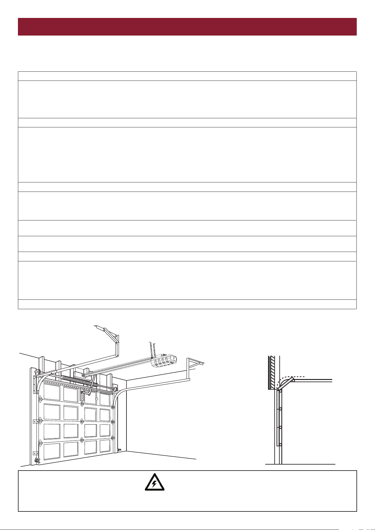
TYPICAL DOOR INSTALLATION
Door Types
Commercial spring-balanced sectional
door with curved track, up to 3.0m
high and up to 15m² in area.
WARNING
A 240V General Purpose Outlet (GPO) ie. Power Point must be available in close proximity to the operator.
This fitting is not part of the operator hardware and must be supplied by the consumer.
4
INTRODUCTION
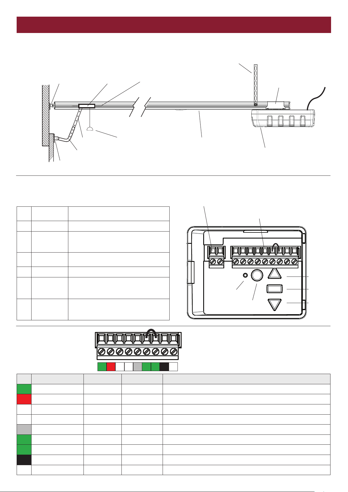
OPERATOR OVERVIEW
4
Header Bracket Trolley
Door arm Manual Release
J-Bar
Door Connection Bracket
CONTROL PANEL OVERVIEW
Control Panel is accessible under the cover on the rear of the operator.
1. Up Button
2. Prog Button Used to program door limits and other features
3. Down Button
4. Learn Button
5. Indicator LED Used to indicate various programming modes
External
6.
Accessory
Power
7. Terminal Blocks
Used for initial programming, driving the door
up and for displaying diagnostic codes - Digit 1
Used for initial programming, to drive the door
down and for displaying diagnostic codes Digit 2
Used for programming remote access devices
and manual learning of forces
30 Vdc 50mA available. Constant supply (no
low standby) unregulated.
Used to configure external accessories. See
chart below for the function of each terminal
block.
Chain
Hanging bracket
Rail
6. External Accessory Power (30V DC)
7. Terminal Blocks
5. Indicator LED
4. Learn Button
Operator Mounting
Bracket
Power
cord
Operator
1. Up
2. Stop
3. Down
Terminal Block Functions
0 1 2 2 3 4 5 6 7
No. Function Colour Polarity Comment
0 E-Serial port Green +ve Serial Communication Input
1 Trigger input Red +ve Dry Contact input for access control accessories
2 Ground White -ve Common terminal for access control accessories
2 Ground White -ve Common terminal for Safety Beams
3 Safety Beam Grey +ve Safety Beam Input: (compatible with supplied safety beams only)
4 Emergency Stop Green +ve Dry Contact input for Emergency Stop N/C
5 Emergency Stop Green -ve Common terminal for Emergency Stop
6 24Vdc power supply Black +ve Accessory power output: (24 Vdc 150 mA) while door is in motion (regulated)
7 24Vdc power supply White -ve Accessory power output: (24 Vdc 150 mA) while door is in motion (regulated)
5
INSTALLATION
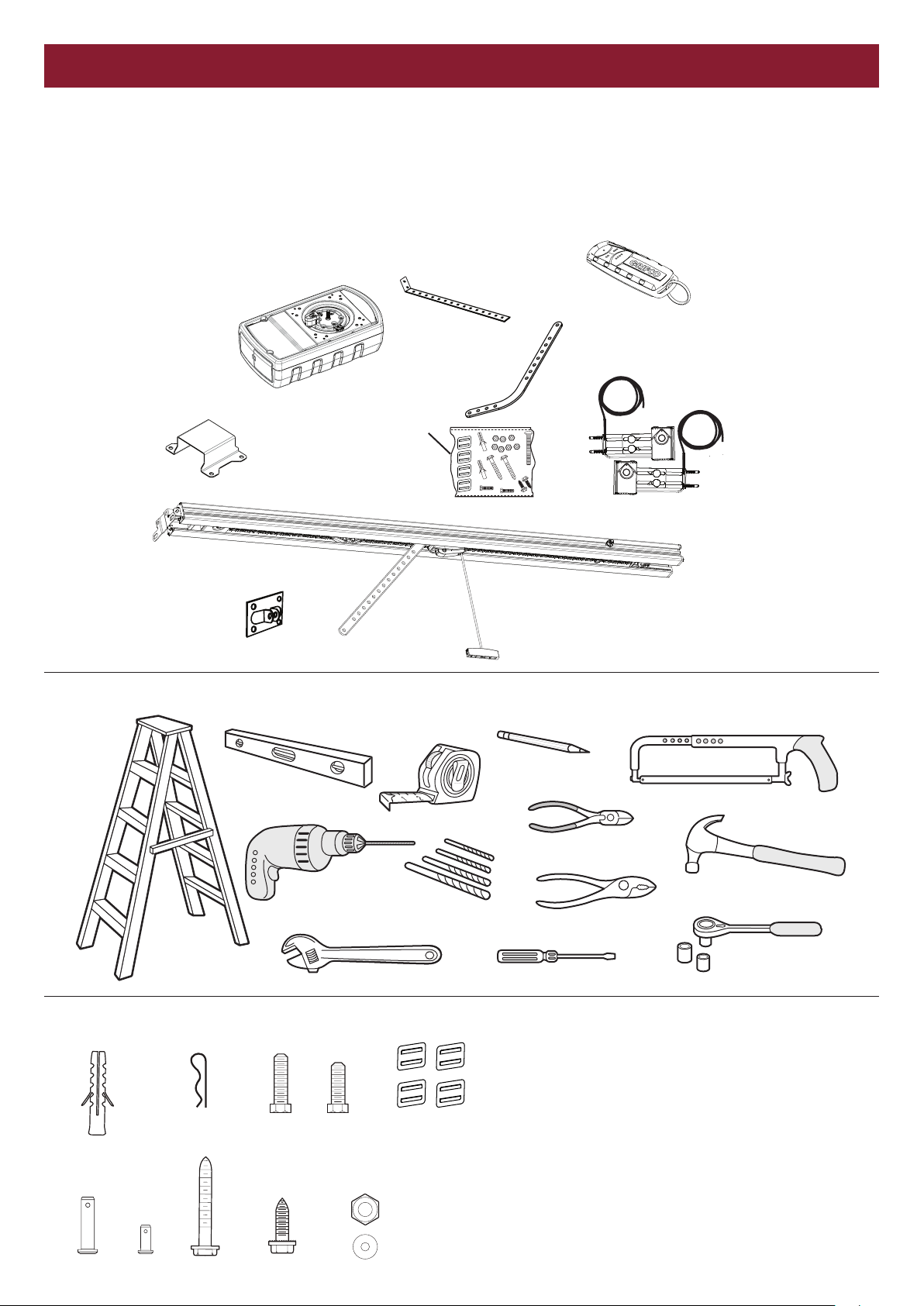
CARTON INVENTORY
NOTE
The commercial sectional door operator is supplied in two separate cartons.
GLD-SDO contains the operator, fitting hardware and accessories.
GLD-R2.4M or GLD-R3.0M contain the complete, assembled rail and some hardware.
Hanging Brackets
Grifco 4-Channel
Transmitter
Operator
Operator Mounting
Bracket
Header Bracket
Door Connection
Bracket
TOOLS REQUIRED
Cable
Clips x 4
Mounting
Hardware
Door arm
J-Bar
Safety Beams
Rail
Manual Release
HARDWARE PROVIDED
(1) 4x
(5) 1x (6) 2x (7) 4x (8) 8x
(1) Wall plug
(2) R clip
(3) Hexagonal head screw M8x25
(4) Hexagonal head screw M8x20
(5) Clevis pin 8mm
(4) 2x (11) 4x(3) 2x(2) 3x
(9) 4x
(10) 4x
6
(6) Clevis pin 6mm
(7) Screw ST6 x 50 mm
(8) Screw ST6,3 x 18 mm
(9) Nut M8
(10) Flat washer M8
(11) Cable Clips
 Loading...