

Grifco eDrive +2.0 Installation And User Manual
installation and users
manual for eDrive +2.0
commercial door opener
www.grifco.com.au
www.grifco.co.nz
D-M-RDO/006
413062
Chamberlain Australia Pty Ltd
PO Box 1446, Lane Cove
NSW 1595, Australia
Phone toll free 1800 474 326
Chamberlain New Zealand Ltd
PO Box 100-221
North Shore 0745, New Zealand
Phone toll free 0800 653 667
2
THESE ARE IMPORTANT SAFETY INSTRUCTIONS. FOLLOW ALL INSTRUCTIONS AS INCORRECT
INSTALLATION CAN LEAD TO SEVERE INJURY OR DEATH
An electrician must disconnect electric power to the commercial
door opener before making repairs or removing covers.
Keep commercial door balanced. Sticking or binding doors must
be repaired. Commercial doors, door springs, pulleys, brackets
and their hardware are under extreme tension and can cause
serious personal injury. Do not attempt to loosen, move or adjust
them. Call for commercial door service.
Do not wear rings, watches or loose clothing while installing or
servicing a commercial door opener.
To avoid serious personal injury from entanglement, remove all
ropes connected to the commercial door before installing the
door opener.
Installation and wiring must be in compliance with your local
building and electrical codes. Connect the power supply cord only
to properly earthed mains.
Moisture and water can destroy the electronic components.
Make sure under all circumstances that water moisture or storage
moisture cannot penetrate the electronics. The same applies for
openings and cable entries.
Permanently fasten all supplied labels adjacent to the wall control
as a convenient reference and reminder of safe operating procedures.
Disengage all existing commercial door locks to avoid damage to
commercial door. Install the wall control (or any additional push
buttons) in a location where the commercial door is visible dur-
ing operation . Do not allow children to operate push button(s)
or remote control(s). Serious personal injury from a closing com-
mercial door may result from misuse of the opener.
Activate opener only when the door is in full view, free of obstructions and opener is properly adjusted. No one should enter
or leave the building while the door is in motion.
After the installation a final test of the full function of the system and the full function of the safety devices must be done.
Make sure that people who install, maintain or operate the door
follow these instructions. Keep these instructions in a safe place
so that you can refer to them quickly when you need to.
Safety Symbol and Signal Word review
This commercial door opener has been designed and tested to offer safe service provided it is installed, operated, maintained
and tested in strict accordance with the instructions and warnings contained in this manual.
WARNING
WARNING
CAUTION
Mechanical
Electrical
When you see this Signal Word on the following pages, it will alert you
to the possibility of damage to your commercial door and/or the commercial door opener if you do not comply with the cautionary statements that accompany it.
When you see these Safety Symbols and Signal Words on the following
pages, they will alert you to the possibility of serious injury or death if
you do not comply with the warnings that accompany them. The hazard
may come from something mechanical or from electric shock.
When operating a biased-off switch, make sure that other persons are kept away.
The opener cannot be used with a driven part incorporating a
wicket door (unless the opener cannot be operated with the
wicket door open).
The actuating member of a biased-off switch is to be located
within direct sight of the door but away from moving parts.
Unless it is key operated, it is to be installed at a minimum height
of 1500mm and not accessible to the public.
This appliance is not intended for use by persons (including children) with reduced physical, sensory or mental capabilities, or
lack of experience and knowledge, unless they have been given
supervision or instruction concerning use of the appliance by a
person responsible for their safety. Children should be supervised
to ensure that they do not play with the appliance.
If the opener is installed at a height less than 2.5 metres from
floor level or any other level from which the unit can be accessed (eg mezzanine) the installer is responsible to fit guards to
the opener to prevent access to the chain drive.
Motor may become hot during operation. Appropriate clearance and/or shielding should be supplied by the installer to
ensure any cabling, wiring and/or other items cannot come in
contact with the motor. If temperature rise exceeds 50⁰C all
fixed wiring insulation must be protected, for example, by
insulating sleeving having an appropriate temperature rating.
WARNING: Important safety instructions. It is important for the
safety of persons to follow all instructions. SAVE these instructions.
Use the commercial door opener for its intended purpose.
eDrive +2.0 openers are designed for operating spring balanced
roller shutters, spring balanced roller doors and counterweighted
bi-fold and vertical lift doors.

3
TABLE OF CONTENTS
Safety instructions 2
Introduction 4
Identifying your eDrive +2.0 4
Planning 5
Installation 6-10
Mounting the unit 6-7
Installing hand chain 8
Connecting power 9
Controller 10
Installing controller 10
ACEM 10
Setup and adjustment 11-13
Checking power 11
Door direction 11
Changing door direction 11
Setting Limits 12
Optional third limit 13
Operation 13
Door behaviour and Entrapment Protection inputs 14-15
Door behaviour modes 14
Setting door behaviour 14
Installing Entrapment Protection Devices 15
Additional switchgear / Accessories 15
Toggle Input (2 wire) 15
Typical Car Park Application (example) 16
Main Control Board (MCB) layout 17
Accessories 18
Forklift/Wall Remote 18
3 Button Key Ring Remote 18
Wireless Wall Control 18
Wireless Keypad 18
Infrared (IR) Reflective Beam 18
STAR1000EVO Transmitter Management System 18
Auto Close & Wireless Accessory set up 19-20
Maintenance 21
Troubleshooting 22-23
Warranty 24
4
Congratulations on your purchase of the Grifco® eDrive +2.0 Commercial Door Opener. The eDrive +2.0 is a state-of-the-art
opener using sophisticated digital electronics and robust mechanical gearing that provides a balance of user friendly operation
and high level technology, coupled with exciting new standard features.
New standard features include:
Radio on Board
With Radio on Board as standard, the new eDrive +2.0 no longer requires an additional Receiver Card for wireless accessory connectivity.
Auto Close
A built-in Auto Close feature can now be enabled with up to 10 - 300 seconds delay, adjustable in 10 second increments.
Quick Connect Easy Plug-in Terminal
eDrive +2.0 now features more robust pluggable terminal blocks making installation of Entrapment Protection and other devices
easier.
Toggle Input Grifco® eDrive +2.0 features a two-wire quick connect plug-in toggle input which allows direct connection of an external devices such as a single button open/close control and access control devices (such as card readers, keypads, key switches
and loop detectors etc.).
Wireless Security Keypad Ready
Simply mount the wireless keypad to the wall to provide;
wireless security access
wireless hold to close
WARNING
Make sure that people who install, maintain or operate the
door follow these instructions. It is advised that the instruction be kept in a safe place so that you can refer to
them quickly when you need to.
INTRODUCTION
CAUTION
Please remove any locks fitted to the door before operation in order to prevent damage to the door.
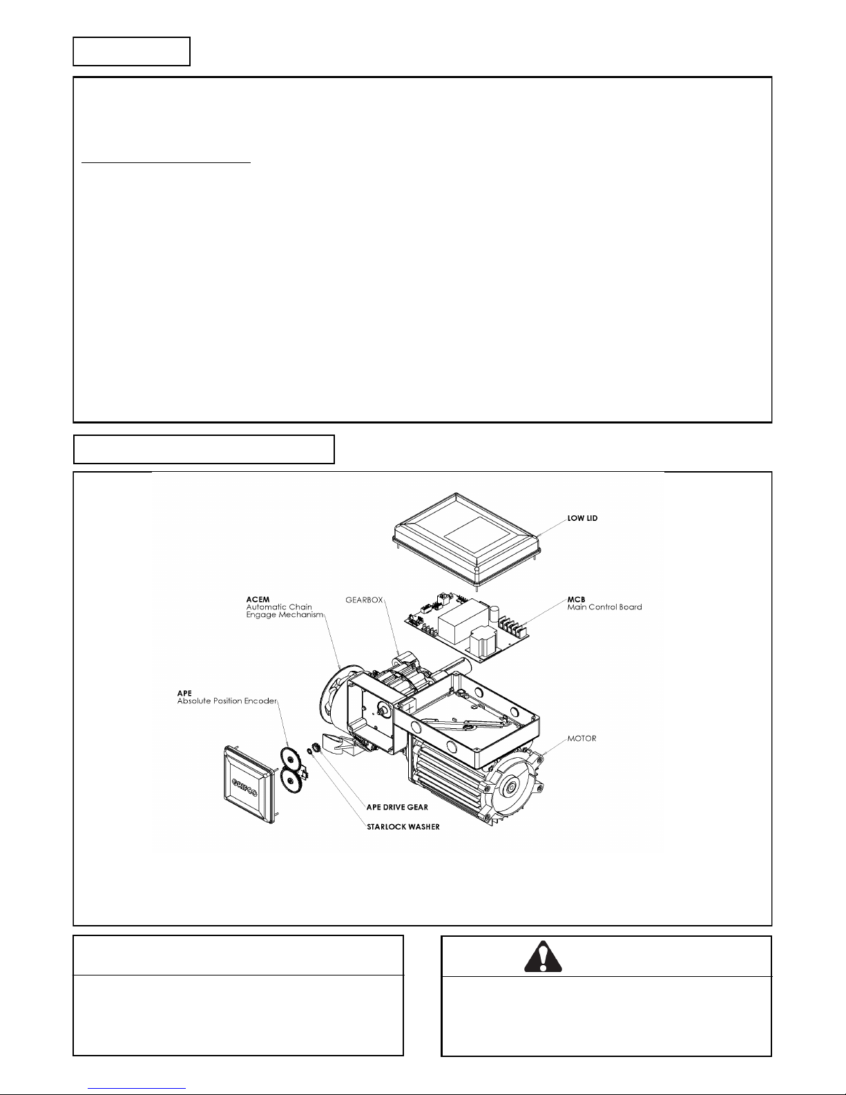
Your standard eDrive +2.0 includes the opener, mounting bolts, and controller (containing controller cable and conduit en-
tries).
Some optional accessories may also be included such as a mounting plate, sprockets, chain, beams & transmitter.
Appearance may vary with different motor, gearbox and controller types
IDENTIFYING YOUR eDrive +2.0
5
PLANNING
WARNING
The door guides must be fitted with mechanical stops
that prevent the bottom rail from passing through in
the opening direction. The opener should stall if driven
into the mechanical stops.
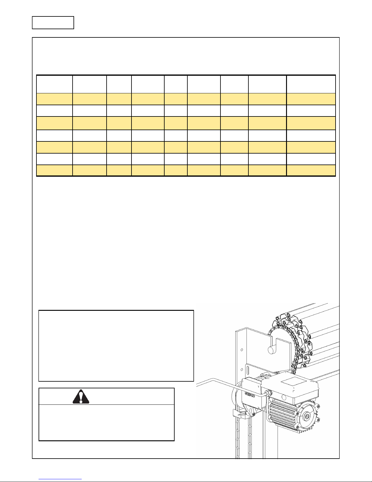
Identify the type and dimensions of your commercial rolling door. A check of the application is recommended to ensure suitabi lity of the opener model to the door.
Installer is to check that the temperature range marked on the drive is suitable for the location.
Note: eDrive +2.0 openers are not recommended for use on residential garage doors.
* Door size is stated as a guide only. Refer to "max door mass" to assess drive suitability.
** Maximum door mass is:
- before spring balancing. Door must be spring balanced.
- based on at least 4:1 sprocket ratio, and curtain load with 200mm drum diameter.
If any conditions above are not met, some consideration should be given to increasing the sprocket ratio, or opener size. The
opener should be installed on the most suitable side of the commercial door. Consider an In-Board Mounting Kit (P/N IBMK) if
there is insufficient side room. Select the side that meets the requirements listed below.
Must have minimum distance of 15mm between mounting plate and door drum sprocket (refer pg 6 image no. 1)
Must have minimum distance of 10mm between APE housing and imposing structure (refer pg 7 image no. 4)
Must have minimum overhead clearance of 150mm from the main control housing (refer pg 7 image no. 5)
Note: Before installing the opener, check that the commercial door is in good mechanical condition, correctly balanced and
opens and closes properly.
Opener Build Rated Load
(Nm)
Hp Duty
Rating (%)
Phase Door size
(m2)*
kW Amp Max Door Mass
(KG)**
ML5053 53 0.5 10 3 18 0.37 1.6 270
ML5103 140 1.0 10 3 36 0.75 2.4 540
MH5103 80 1.0 30 3 30 0.75 2.0 450
ML5153 190 1.5 10 3 50 1.1 2.9 890
ML5051 67 0.5 10 1 18 0.37 3.5 270
ML5102 85 1.0 10 1 36 0.75 6.0 480
MH5102 73 1.0 30 1 30 0.75 4.4 450
Doors of Rigid Construction
When using a Grifco® eDrive +2.0 on commercial doors of ‘rigid’
construction (eg. bi-fold, vertical lift, sectional or continuous
steel roller doors etc.), consider that the limit confirmation
movement requires a 1/4 turn of the output shaft downward at
the closed position (refer to page 12 for more information on
how to reset the re-find movement). Sufficient mechanical freedom must be provided at the closed position for this
reason.
6
INSTALLATION SECTION
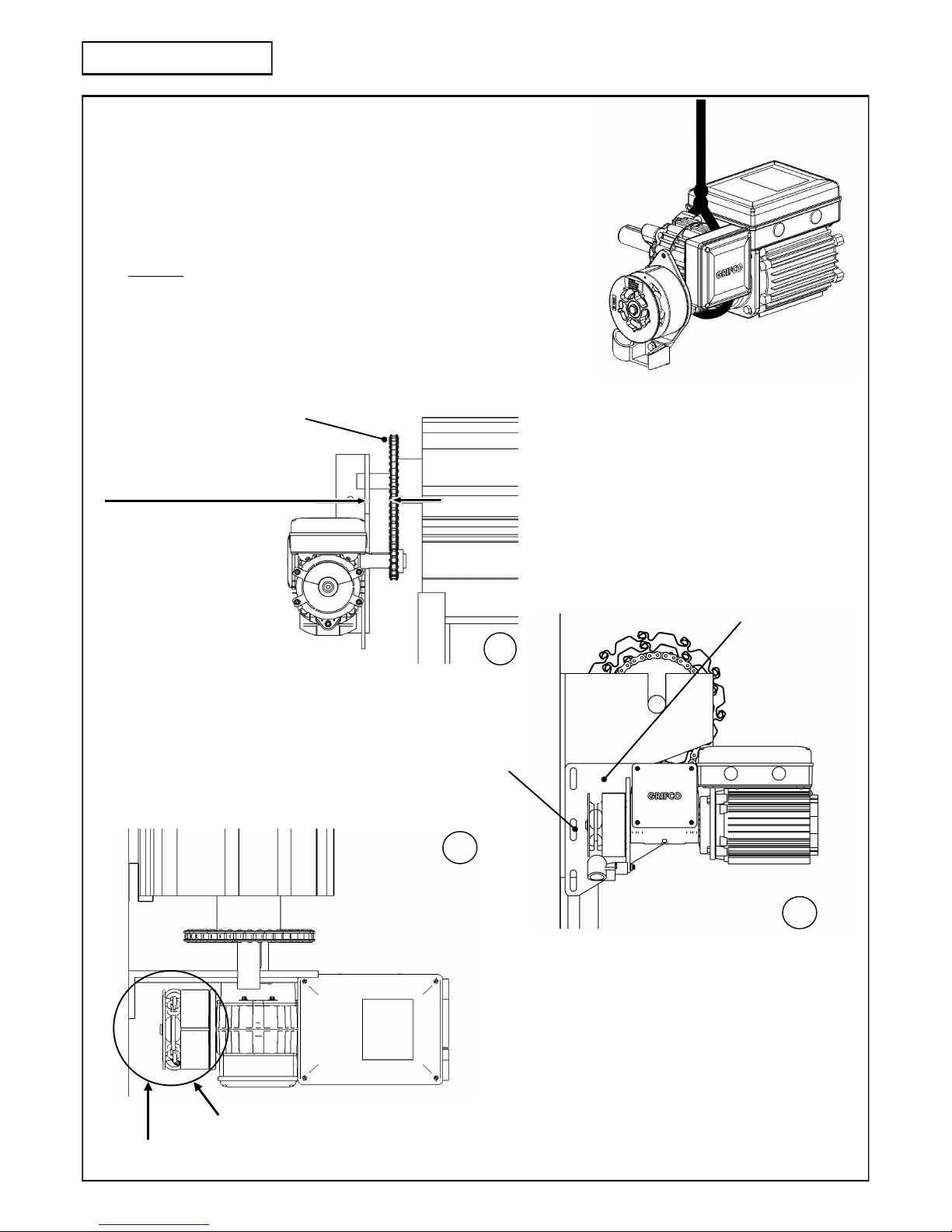
Alignment of door sprocket to output shaft of
eDrive +2.0 (see left)
Mounting the unit
The eDrive +2.0 is typically flag mounted below the door drum so that the
opener shaft points toward the door opening and lies beneath the sprocket of the
door drum. For mounting you will need to either secure the opener to the roller
shutter head plate with prepared holes or slots, or use a mounting plate that will
need fixing via a wall angle or similar existing structure.
Note: The eDrive +2.0 is not designed to be installed upside down. The chain
guide must not be repositioned.
It is strongly recommended that a suitably rated lifting strap be used to raise the
opener to a necessary height, shown right. A suitable lifting device should be connected to a secure support beam (or similar) above the door axle.
When assessing and selecting an appropriate mounting location, the
following considerations should be made:
Clear accessible space needed below for safe chain operation
Distance between mounting
plate and door sprocket
Min 15mm - Max 100mm
1
Drive chain
Mounting plate slots allow the chain tension to
be adjusted through vertical movement of the
opener (see right)
Mounting plate
2
Mounting plate slots
3
Clear path for manual chain to hang downward (refer pg 8 image no. 7 & 8)
Distance between ACEM and wall 40 mm
7
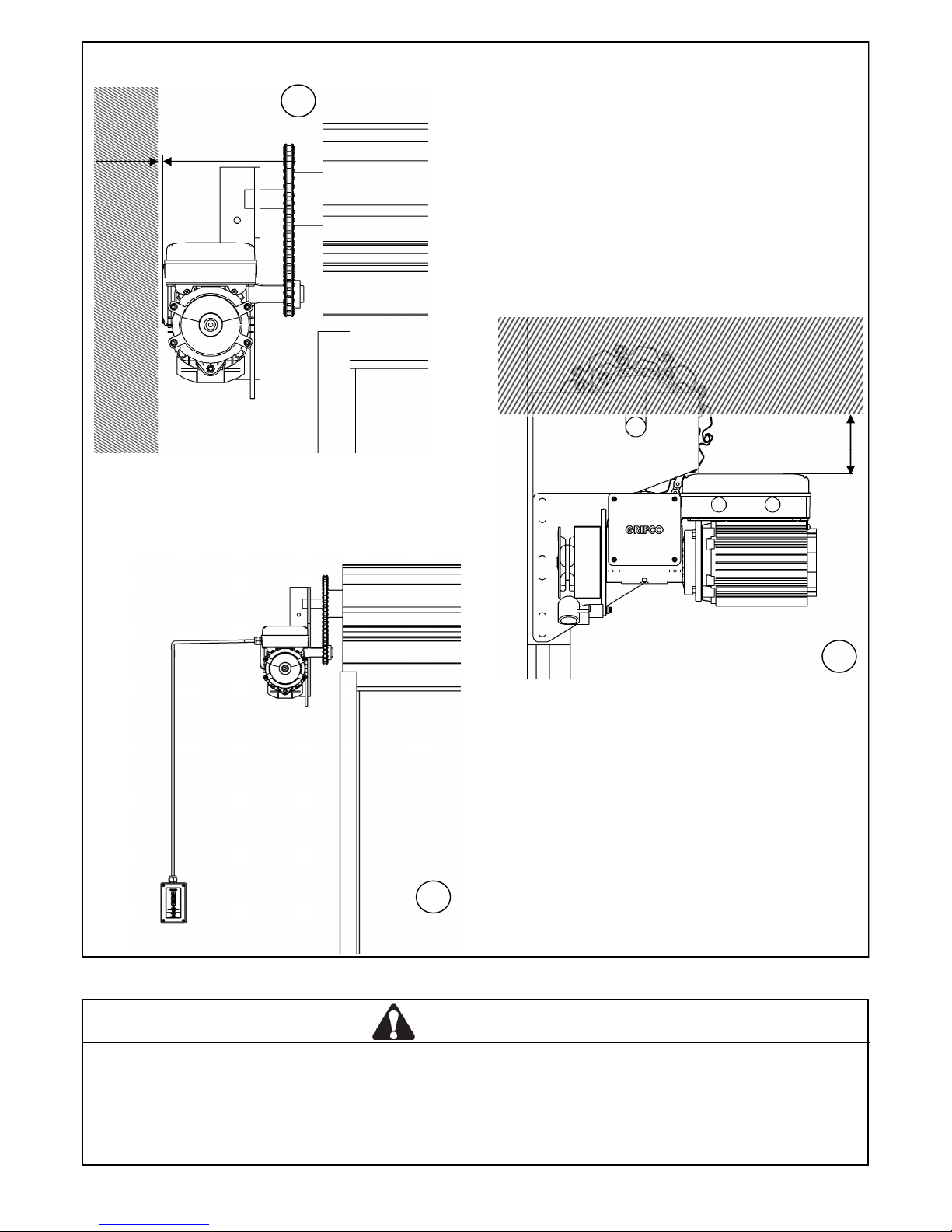
Mounting the unit (continued)
Side room to imposing structures (see left).
The eDrive +2.0 APE housing is not a serviceable area and can be
located within 10mm of an imposing structure without affecting installation. Where there is insufficient side room, consider using the
opposite hand opener and mount inboard with a Grifco® Inboard
Mounting Kit, P/N IBMK.
Limited head room (see right).
The eDrive +2.0 main control housing is a serviceable area and will
need to be accessed by service personnel. Refer below for options
on how to overcome problems in which sufficient head room is
not available.
If there is insufficient head room above the eDrive +2.0
opener to allow servicing then a Grifco® Wall Mount Kit
(P/N WMK2) or Grifco® Rotation Bracket (P/N RBK2)
can be used to reposition the main control housing.
Please contact your local dealer or Chamberlain for
more information.
Location of Controller (see left).
Controller has 6 metres of cable with RJ45 ends ready
to connect the eDrive +2.0 opener to the controller.
eDrive +2.0 Controller Extension Kit (P/N ESK01) is
available if needed.
WARNING
When Securing the eDrive +2.0 opener with the 4 x M12 x 40mm long fasteners (based on a 8mm mounting plate) and spring
washers provided, it is critical to ensure that the applied torque is between 80-90Nm. When mounting through thicker sections,
ensure a minimum of 30mm of screw thread is engaged with the female thread. Use of incorrect fasteners or torque may cause
serious product damage, personal injury or death. When fixing through a slotted plate, ensure that the slots are no wider than
13mm as a spring washer may not be adequate in outside diameter to support the hexagon head.
6
5
150mm
Minimum
4
10mm Minimum
4
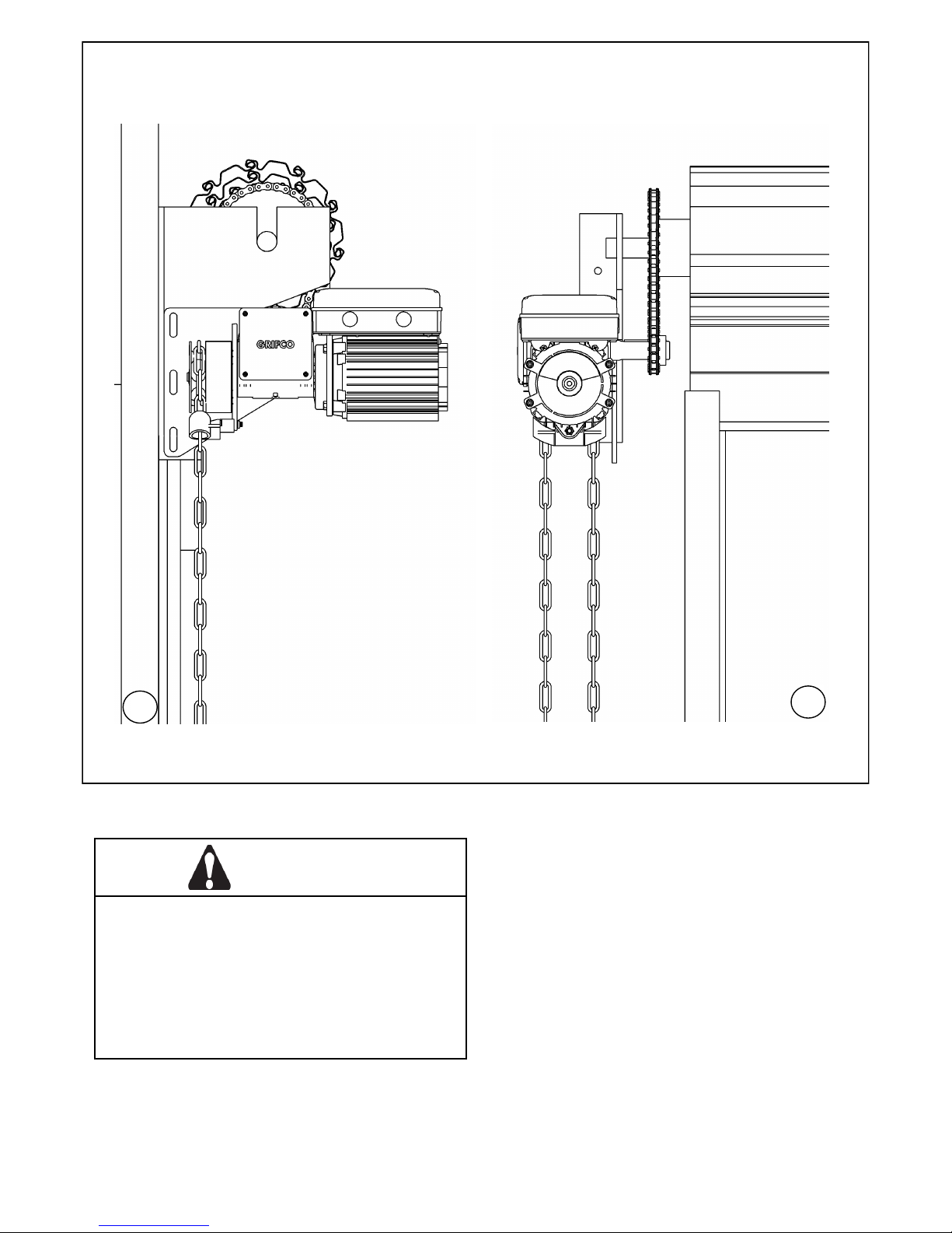
8
Installing Hand Chain (Use 5mm long link chain only)
Ensure the mounting position allows the hand chain to hang free of obstructions.
Ensure hand chain is not twisted when making the join!
7
8
CAUTION
Motor may become hot during operation. Appropriate
clearance and/or shielding should be supplied by the installer to ensure any cabling, wiring and/or other items
cannot come in contact with the motor. If temperature
rise exceeds 50⁰C all cable wiring must be shrouded.
Fixed wiring insulation must be protected, for example, by
insulating sleeving having an appropriate temperature
rating.
 Loading...