

Page 1
“ZNR ” Transient/Surge Absorbers
Type:
D
Series:
V
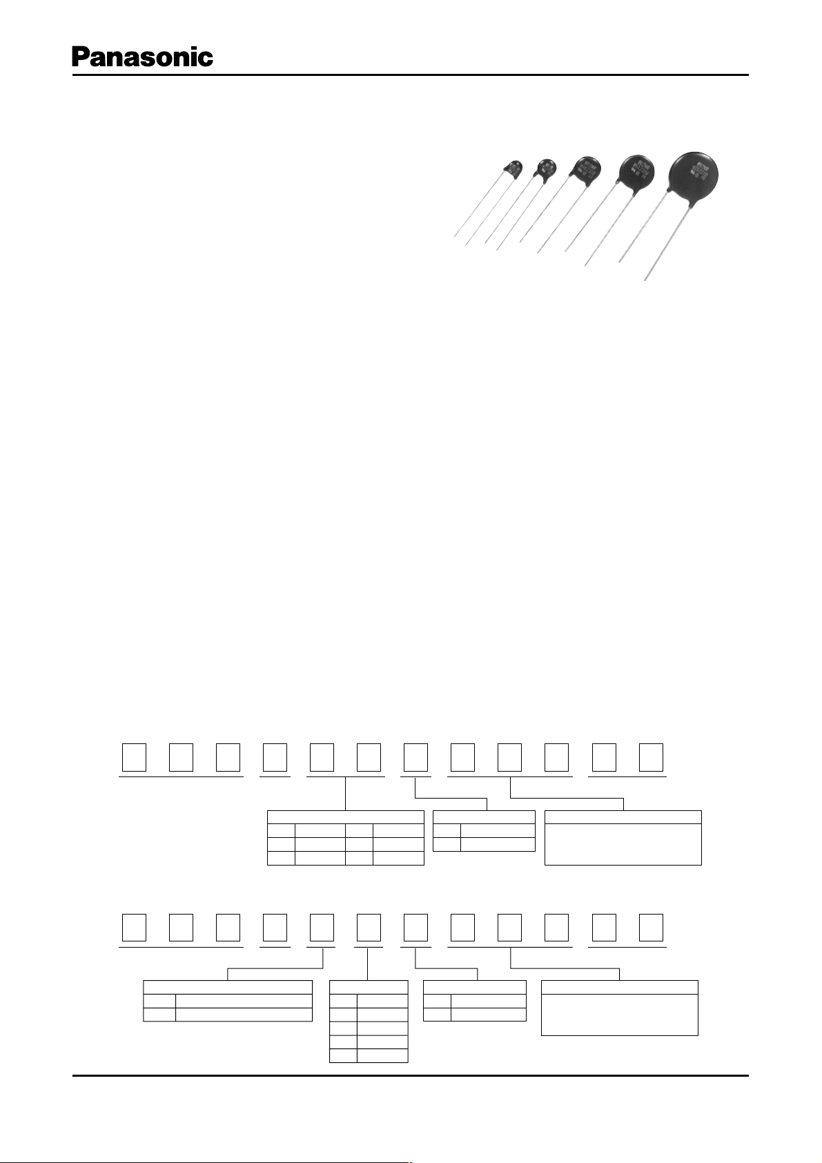
“ZNR” Transient/Surge Absorber, Series V, Type D
features large surge current and energy handling
capability for absorbing transient overvoltage in a
compact size.
“ZNR” Transient/Surge Absorbers (Type D)
■ Features
● Large withstanding surge current capability in compact
sizes
● Large “Energy Handling Capability” absorbing transient
overvoltages in compact sizes
● Wide range of varistor voltages
● The standard products shown below have received
UL, CSA and VDE standards
Varistor voltage 82-150V : UL, VDE
Varistor voltage 200V over : UL, CSA, VDE
(cf. Application Notes for UL/CSA, VDE recognized
parts on page 103 to 104)
● RoHS compliant
■ Related Standards
● UL1414, UL1449
● CSA C22.2 No.1 Class 2221 01
VDE CECC42000, CECC42200, CECC42201, IEC61051
● “Type Designation(UL)”, “Part Number(CSA)” ,“Style
Ref. (VDE)
”
Are not registered by product Part No..
(Refer to page 103, for the details)
■ Explanation of Part Numbers (Bulk)
1
E
2
R
3
Z
4 5678910
V
■ Recommended Applications
● Transistor, diode, IC, thyristor or triac semiconductor
protection
● Surge protection in consumer electronic equipment
● Surge protection in communication, measuring or
controller electronics
● Surge protection in electronic home appliances, gas or
petroleum appliances
● Relay or electromagnetic valve surge absorption
■ Handling Precautions
See Page 113 to 115
■ Packaging Specifi cations
See Page 144
11 12
D
Product Code
Series
05
07
09
Element Size
f
5mm
f
7mm
f
10 mm
Design No.
f
10 mm
10
f
14 mm
14
f
20 mm
20
Lead Configuration
D
Straight Lead
Crimped Lead
V
✽ Excludingf20.
✽ Onlythe lead cut
✽
Norminal Varistor Voltage
The first twodigits are significant
figures and thethird one denotes
the number ofzeros following.
■ Explanation of Part Num bers (Taping)
1
E
Design and specifi cations are each subject to change without notice. Ask factory for the current technical specifi cations before purchase and/or use.
Should a safety concern arise regarding this product, please be sure to contact us immediately.
2
R
Product Code
Taping / Packaging
AtoD
Radial Taping (P
EtoH
Radial Taping (P
3
Z
4 5678910
V
Series
0=12.7 mm)
0=15.0 mm)
Element Size
f
5
f
7
f
9
10 mm
f
A
10 mm
f
14 mm
E
5mm
7mm
D
Lead Configuration
D
Straight Lead
Crimped Lead
V
The first twodigits are significant
figures and thethird one denotes
the number ofzeros following.
11 12
Design No.
Nominal Varistor Voltage
Feb. 200 6
Page 2
“ZNR” Transient/Surge Absorbers (Type D)
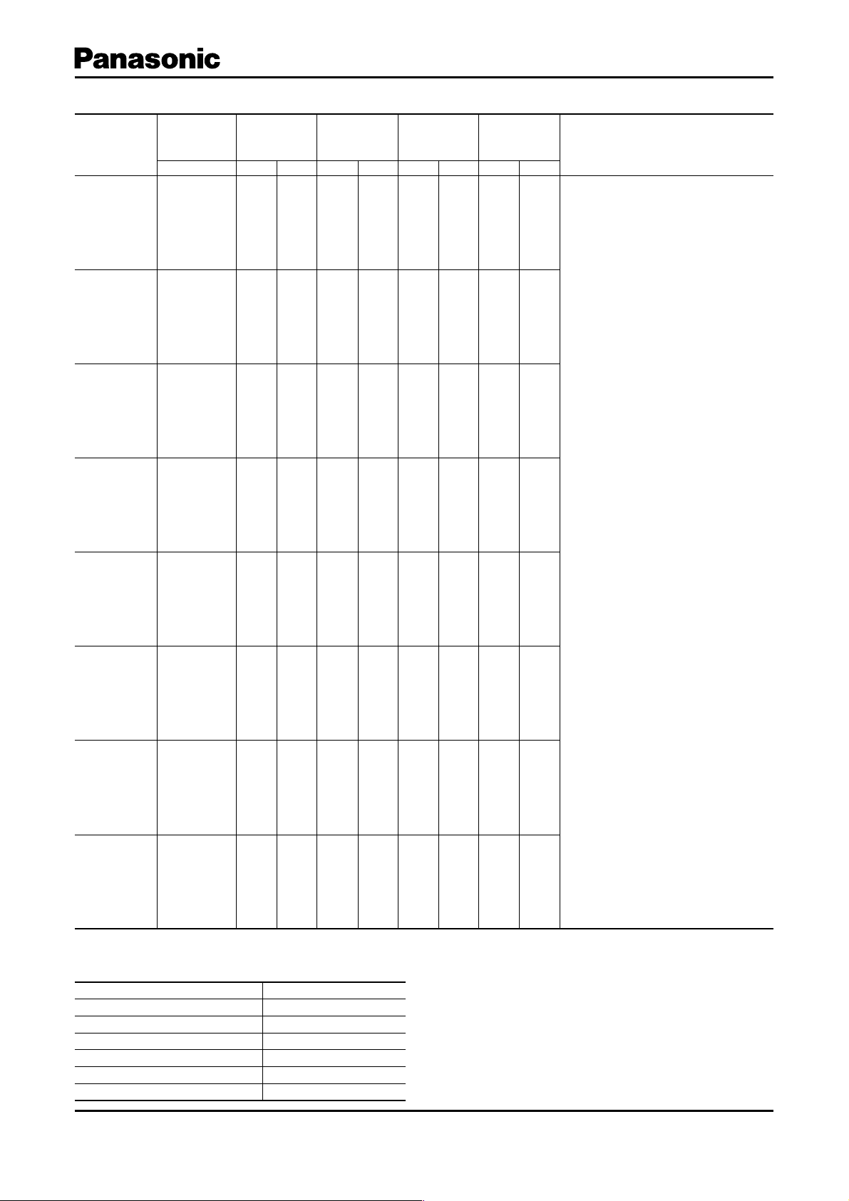
■ Reference Guide to Standard Products (ERZV쑗쑗D180 to ERZV쑗쑗 D680)
✽
Maximum
Allowable
Voltage
ACrms (V )
11 14
14 18
17 22
20 26
25 31
30 38
35 45
40 56
DC (V) max.(V)
Varistor
Part No.
ERZV05D180
ERZV07D180
ERZV09D180
ERZV10D180
ERZV14D180
ERZV20D180
ERZV05D220
ERZV07D220
ERZV09D220
ERZV10D220
ERZV14D220
ERZV20D220
ERZV05D270
ERZV07D270
ERZV09D270
ERZV10D270
ERZV14D270
ERZV20D270
ERZV05D330
ERZV07D330
ERZV09D330
ERZV10D330
ERZV14D330
ERZV20D330
ERZV05D390
ERZV07D390
ERZV09D390
ERZV10D390
ERZV14D390
ERZV20D390
ERZV05D470
ERZV07D470
ERZV09D470
ERZV10D470
ERZV14D470
ERZV20D470
ERZV05D560
ERZV07D560
ERZV09D560
ERZV10D560
ERZV14D560
ERZV20D560
ERZV05D680
ERZV07D680
ERZV09D680
ERZV10D680
ERZV14D680
ERZV20D680
Measuring Current of Varistor Voltage
✽
5 Series ( ERZV0 5D180 to ERZV 05D68 0): 0.1 mA
Others: 1 mA
Voltage
(V)
18
(16–20)
22
(20–24)
27
(24– 30)
33
(30–36)
39
(35–43)
47
(42–52)
56
(50–62)
68
(61–75)
● Rated Power
Part Number Rated Power (W)
ERZV05D180 to ERZV05D680
ERZV07D180 to ERZV07D680
ERZV09D180 to ERZV09D680
ERZV10D180 to ERZV10D680
ERZV14D180 to ERZV14D680
ERZV20D180 to ERZV20D680
Clamping
Voltage
@8/20µs
40
36
36
36
36
36
48
43
43
43
43
43
60
53
53
53
53
53
73
65
65
65
65
65
86
77
77
77
77
77
104
93
93
93
93
93
123
110
110
110
110
110
150
135
135
135
135
135
0.01
0.02
0.05
0.05
0.10
0.20
Ip (A)
1
2.5
5
5
10
20
1
2.5
5
5
10
20
1
2.5
5
5
10
20
1
2.5
5
5
10
20
1
2.5
5
5
10
20
1
2.5
5
5
10
20
1
2.5
5
5
10
20
1
2.5
5
5
10
20
Maximum
Energy
(Joule)
10/1000 µs
0.6
1.1
2.6
2.6
5. 2
13
0.7
1.3
3.2
3.2
6.3
16
0.9
1.6
3.9
3.9
7.8
19
1.1
2.0
4.8
4.8
9.5
24
1.2
2.4
5.6
5.6
11
28
1.5
2.8
6.8
6.8
14
34
1.8
3.4
8.1
8.1
16
41
2.2
4.1
9.8
9.8
20
49
2 ms 1 time
0.4
0.9
2.2
2.2
4.3
12
0. 5
1.1
2.6
2.6
5.3
14
0.7
1.3
3.2
3.2
6.5
17
0.8
1.6
4.0
4.0
7.9
21
0.9
1.9
4.7
4.7
9.4
25
1.1
2.3
5.6
5.6
11
30
1.3
2.7
6.7
6.7
13
36
1.6
3.3
8.2
8.2
16
44
Maximum
Peak Current
@8/20µs(A)
2 times
250
125
500
250
1000
1000
2000
3000
1000
1000
2000
3000
1000
1000
2000
3000
1000
1000
2000
3000
1000
1000
2000
3000
1000
1000
2000
3000
1000
1000
2000
3000
1000
1000
2000
3000
250
500
250
500
250
500
250
500
250
500
250
500
250
500
500
500
1000
2000
125
250
500
500
1000
2000
125
250
500
500
1000
2000
125
250
500
500
1000
2000
125
250
500
500
1000
2000
125
250
500
500
1000
2000
125
250
500
500
1000
2000
125
250
500
500
1000
2000
● Operating Temperature Range: –40 to 85
● Storage Temperature Range: –40 to 125
Recommended Applications
For the low voltage circuit
°C
°C
Design and specifi cations are each subject to change without notice. Ask factory for the current technical specifi cations before purchase and/or use.
Should a safety concern arise regarding this product, please be sure to contact us immediately.
Feb. 200 6
Page 3

“ZNR” Transient/Surge Absorbers (Type D)
■ Reference Guide to Standard Products (ERZV쑗쑗D820 to ERZV쑗쑗 D182)
Part No.
ERZV05D820
ERZV07D820
ERZV09D820
ERZV10D820
ERZV14D820
ERZV20D820
ERZV05D101
ERZV07D101
ERZV09D101
ERZV10D101
ERZV14D101
ERZV20D101
ERZV05D121
ERZV07D121
ERZV09D121
ERZV10D121
ERZV14D121
ERZV20D121
ERZV05D151
ERZV07D151
ERZV09D151
ERZV10D151
ERZV14D151
ERZV20D151
ERZV05D201
ERZV07D201
ERZV09D201
ERZV10D201
ERZV14D201
ERZV20D201
ERZV05D221
ERZV07D221
ERZV09D221
ERZV10D221
ERZV14D221
ERZV20D221
ERZV05D241
ERZV07D241
ERZV09D241
ERZV10D241
ERZV14D241
ERZV20D241
ERZV05D271
ERZV07D271
ERZV09D271
ERZV10D271
ERZV14D271
ERZV20D271
ERZV05D331
ERZV07D331
ERZV09D331
ERZV10D331
ERZV14D331
ERZV20D331
ERZV05D361
ERZV07D361
ERZV09D361
ERZV10D361
ERZV14D361
ERZV20D361
ERZV05D391
ERZV07D391
ERZV09D391
ERZV10D391
ERZV14D391
ERZV20D391
Varistor
Voltage
(V)
82
(74–90)
100
(90–110)
120
(108–132)
150
(135–165)
200
(185–225)
220
(198–242)
240
(216–2 64)
270
(247–303)
330
(297–363)
360
(324–39 6 )
390
(351–429)
✽
Maximum
Allowable
Voltage
ACrms (V )
50 65
60 85
75 100
95 125
130 170
140 180
150 200
175 225
210 270
230 300
250 320
DC (V) max.(V)
Clamping
Voltage
@8/20 µs
Ip (A)
145
135
135
135
135
135
175
165
165
165
165
165
210
200
200
200
200
200
260
250
250
250
250
250
355
340
340
340
340
340
380
360
360
360
360
360
415
395
395
395
395
395
475
455
455
455
455
455
570
545
545
545
545
545
620
595
595
595
595
595
675
650
650
650
650
650
10
25
25
50
100
10
25
25
50
100
10
25
25
50
100
10
25
25
50
100
10
25
25
50
100
10
25
25
50
100
10
25
25
50
100
10
25
25
50
100
10
25
25
50
100
10
25
25
50
100
10
25
25
50
100
5
5
5
5
5
5
5
5
5
5
5
Maximum
Energy
(Joule)
10/1000 µs
3.5
7
14
14
28
56
4
8.5
17
17
35
70
5
10
20
20
42
85
6.5
13
25
25
53
106
8.5
17.5
35
35
70
140
9
19
39
39
78
155
10.5
21
42
42
84
168
11
24
49
49
99
190
13
28
58
58
115
228
16
32
65
65
130
255
17
35
70
70
140
275
Peak Current
@8/20 µs (A)
2 ms 1 time
2.5
5
10
10
20
40
1750
3500
3500
6000
10000
3
6
12
12
25
50
1750
3500
3500
6000
10000
3.5
7
14.5
14.5
30
60
1750
3500
3500
6000
10000
4.5
9
18
18
37.5
75
1750
3500
3500
6000
10000
6
12.5
25
25
50
100
1750
3500
3500
6000
10000
6.5
13.5
27.5
27.5
55
110
1750
3500
3500
6000
10000
7.5
15
30
30
60
120
1750
3500
3500
6000
10000
8
17
35
35
70
135
1750
3500
3500
6000
10000
9.5
20
42
42
80
160
1750
3500
3500
6000
10000
11
23
45
45
90
180
1750
3500
3500
6000
10000
12
25
50
50
100
195
1750
3500
3500
6000
10000
Maximum
2 times
800
1250
2500
2500
5000
7000
800
1250
2500
2500
5000
7000
800
1250
2500
2500
5000
7000
800
1250
2500
2500
5000
7000
800
1250
2500
2500
5000
7000
800
1250
2500
2500
5000
7000
800
1250
2500
2500
5000
7000
800
1250
2500
2500
5000
7000
800
1250
2500
2500
4500
6500
800
1250
2500
2500
4500
6500
800
1250
2500
2500
4500
6500
600
600
600
600
600
600
600
600
600
600
600
Recommended Applications
Tel ep ho ne , C om munication Line
(DC 48 V)
AC 100 V Line –Line Applications
AC 100 V to 120 V, Line– Line
Applications
AC 100 V to 120 V, Line– Line
Applications
Tel ep ho ne Li ne Applications,
(250 V Insulation Resistance Test
Applicable)
Design and specifi cations are each subject to change without notice. Ask factory for the current technical specifi cations before purchase and/or use.
Should a safety concern arise regarding this product, please be sure to contact us immediately.
Feb. 200 6
Page 4

■ Reference Guide to Standard Products
✽
ACrms (V )
Maximum
Allowable
Voltage
DC (V) max.(V)
275 350
300 385
320 410
385 505
420 560
460 615
510 670
550 745
625 825
680 895
1000 1465
1025
1025
1025
1240
1240
1240
1355
1355
1355
1500
1500
1500
1650
1650
1650
1815
1815
1815
2970
2970
2970
Varistor
Part No.
ERZV05D431
ERZV07D431
ERZV09D431
ERZV10D431
ERZV14D431
ERZV20D431
ERZV05D471
ERZV07D471
ERZV09D471
ERZV10D471
ERZV14D471
ERZV20D471
ERZV07D511
ERZV09D511
ERZV10D511
ERZV14D511
ERZV20D511
ERZV10D621
ERZV14D621
ERZV20D621
ERZV10D681
ERZV14D681
ERZV20D681
ERZV10D751
ERZV14D751
ERZV20D751
ERZV10D821
ERZV14D821
ERZV20D821
ERZV10D911
ERZV14D911
ERZV20D91 1
ERZV10D102
ERZV14D102
ERZV20D102
ERZV10D112
ERZV14D112
ERZV20D112
ERZV10D182CS
ERZV14D182CS
ERZV20D182
Measuring Current of Varistor Voltage
✽
5 Series ( ERZV0 5D820 to ER ZV05D 471): 0.1 mA
Others: 1 mA
Voltage
(V)
430
(387–473)
470
(423–517)
510
(459–561)
620
(558–682)
680
(612–748)
750
(675–825)
820
(738–902)
910
(819–1001)
1000
(900 –1100)
1100
(990 –1210)
1800
(1700–1980)
Clamping
Voltage
@8/20 µs
745
710
710
710
710
710
810
775
775
775
775
775
845
845
845
845
845
1120
1120
1120
Ip (A)
5
10
25
25
50
100
5
10
25
25
50
100
10
25
25
50
100
25
50
100
25
50
100
25
50
100
25
50
100
25
50
100
25
50
100
25
50
100
25
50
100
“ZNR” Transient/Surge Absorbers (Type D)
Maximum
Energy
(Joule)
10/1000 µs
20
40
80
80
155
303
21
42
85
85
175
350
45
92
92
190
382
92
190
382
92
190
382
100
210
420
110
235
460
130
255
510
140
280
565
155
310
620
247
510
1020
2 ms 1 time
13.5
27.5
55
55
110
215
15
30
60
60
125
250
32
67
67
136
273
67
136
273
67
136
273
70
150
300
80
165
325
90
180
360
100
200
400
110
220
440
183
360
720
Maximum
Peak Current
@8/20 µs (A)
2 times
800
600
1750
1250
3500
2500
3500
2500
6000
4500
10000
10000
10000
800
1750
3500
3500
6000
1750
3500
3500
6000
3500
5000
7500
3500
5000
7500
3500
5000
7500
3500
5000
7500
3500
5000
7500
3500
5000
7500
3500
5000
7500
3500
5000
7500
6500
600
1250
2500
2500
4500
6500
1250
2500
2500
4500
6500
2500
4500
6500
2500
4500
6500
2500
4500
6500
2500
4500
6500
2500
4500
6500
2500
4500
6500
2500
4500
6500
2500
4500
6500
Recommended Applications
AC 100 V to 220 V, Line –Line
and
AC 100 V to 220 V, Line –Ground
Applications
AC 100 V to 220 V, Line –Line
and
AC 100 V to 220 V, Line –Ground
Applications
AC 100 to 240 V, Line– Line Applications
AC 100 to 240 V, Line– Ground Applications
AC 380 V, Line– Line and Line –Ground
Applications
(For DC 500 V Insulating Test)
AC 415 V, Li ne–Line a nd Line–G round
Applications
(For DC 500 V Insulating Test)
AC 480 V, Line– Line and Line –Ground
Applications
(For DC 500 V Insulating Test)
Line–Ground Applications
(For AC 120 0 V Withstanding Test)
● Rated Power
Part Number Rated Power (W)
ERZV0 5D820 t o ERZ V05D471
ERZV07D8 20 to ERZ V07D511
ERZV0 9D82 0 to ERZV0 9D511
ERZV10D820 to ERZ V10D182CS
ERZV14D820 to ERZV14D182CS
ERZV2 0D820 to ER ZV20 D182
Design and specifi cations are each subject to change without notice. Ask factory for the current technical specifi cations before purchase and/or use.
Should a safety concern arise regarding this product, please be sure to contact us immediately.
0.10
0.25
0.40
0.40
0.60
1.00
● Operating Temperature Range: –40 to 85
● Storage Temperature Range: –40 to 125
°C
°C
Feb. 200 6
 Loading...