

Page 1
INSTALLATION, OPERATION and
MAINTENANCE MANUAL
MODEL ZF1, ZF2 and ZF3 rated 60 and 90 through 1200A
SINGLE PHASE and THREE PHASE – 2 or 3 LEG CONTROL
SCR POWER CONTROL S
UL/cUL FILE NUMBER – E151547
CE – See last page of manual for CE Declaration of Conformity
AMETEK H DR POW ER S YS TEMS
3563 INTERCHANGE ROAD
COLUMBUS, OH 43204
TEL: 614-308-5500
TOLL FREE: 1-888-797-2685
FAX: 614-308-5506
Page 2
SCR Power Controls/Systems & Power Sup plies
Dear Client:
On behalf of all of AMETEK HDR's employees, I want to take this opportunity to "thank you" for
purchasing an AMETEK HDR Power Systems' SCR Power Control.
We b el i ev e A METEK H DR rep resen ts the b es t overal l sol uti on to y our SCR Power C ontrol n ee ds i n
the industry today. We do this by providing a quality manufactured, reliable unit with fast, on-time
delivery and a competitive price.
All of our employees are dedicated to your success. If you have any questions, comments or
concerns, please call me toll free at 1-888-PWR-CNTL (797-2685).
Sincerely,
AMETEK HDR POWER SYSTEMS
George A. Sites
Vice President
GAS/be
3563 Interchange R oad Co lumbus, OH 43204- 1400 USA Telephone: 614-308-5500 1-888-P WR-C N TL FAX : 614-308- 5506
Page 3

REVISION PAGE
Page Change Revision Date
Various 1 Added DIP Switch information
8/00
31 2 Added EMC to CE Declaration
11/00
NOTE: ALL SPECIFICATIONS SUBJECT TO CHANGE WITHOUT PRIOR NOTICE.
COPYRIGHT 2003 AMETEK HDR POWER SY STEMS
Page 4

TABLE OF CONTENTS
Para.
Title Page
Section 1 - DESCRIPTION
1-1 Models Covered...................................................................................................1
1-2 General Description..............................................................................................1
1-3 Applications.........................................................................................................1
1-4 Specifications.......................................................................................................1
1-5 Options................................................................................................................2
1-6 Operation.............................................................................................................3
1-7 Diagnostic Indicators ...........................................................................................3
Section 2 - INSTALLATION
2-1 Mounting.............................................................................................................4
2-2 Line/Load Power Wiring......................................................................................4
2-3 Fan and Thermostat Wiring................................................................................19
2-4 Input Line Voltage Changes...............................................................................21
2-5 Safety Issues 21
Section 3 - COMM AND S IGNAL CALIBRATION AND WIRING
3-1 Zero and Span Adjustments................................................................................23
3-2 Command Indicator............................................................................................23
3-3 Isolated and Non-Isolated Inputs........................................................................23
3-4 Remote Manual Control.....................................................................................24
3-5 Process Command Signal...................................................................................25
3-6 Auto/Manual Control.........................................................................................25
3-7 ON/OFF Control................................................................................................26
3-8 Shutdown (Disable)............................................................................................27
Section 4 - MAINTENANCE
4-1 Environmental Concerns ....................................................................................28
4-2 Line/Load Power Connections ...........................................................................28
4-3 St atic Precautions when Servicing......................................................................28
4-4 Troubleshooting Typical Symptoms...................................................................28
i
Page 5

Section 5 - SERVICE AND PARTS
5-1 Customer Service...............................................................................................30
5-2 Spare Parts.........................................................................................................30
5-3 Warranty............................................................................................................30
ii
Page 6

TABLES and ILLUSTRATIONS
TABLES
Table Title Page
1 Specifications.............................................................................................................2
2 Lug Size/Torque Information ....................................................................................4
3 Fan Power Requirements .........................................................................................20
4 Troubleshooting Zero Fired SCR Power Controllers .............................................. 29
ILLUSTRATIONS
Figure Title Page
1 Line/Load Power Wiring – ZF1..................................................................................5
2 Line/Load Power Wiring – ZF2..................................................................................5
3 Line/Load Power Wiring – ZF3..................................................................................6
4 Outline and Mounting – ZF1 60 and 90 through 225A...............................................7
5 Outline and Mounting – ZF1 350 and 500A...............................................................8
6 Outline and Mounting – ZF1 650A.............................................................................9
7 Outline and Mounting – ZF1 800 through 1200A.....................................................10
8 Outline and Mounting – ZF2 60 and 90 through 225A.............................................11
9 Outline and Mounting – ZF2 350 and 500A.............................................................12
10 Outline and Mounting – ZF2 650A...........................................................................13
11 Outline and Mounting – ZF2 800 through 1200A.....................................................14
12 Outline and Mounting – ZF3 60 and 90 through 225A.............................................15
13 Outline and Mounting – ZF3 350 and 500A.............................................................16
14 Outline and Mounting – ZF3 650A...........................................................................17
15 Outline and Mounting – ZF3 800 through 1200A.....................................................18
16 Fan & Thermostat Terminals....................................................................................19
17 Remote Manual Control...........................................................................................24
18 Auto/Manual Control...............................................................................................25
19 ON/OFF Control......................................................................................................26
20 Firing Circuit Terminals & DIP Switches..................................................................27
iii
Page 7

Section 1 - DESCRIPTION
1-1 MODELS COVERED
This m an ual covers the ZF 1, ZF2 and Z F3 m odels rated 60 and 90 through 1200 am p ere s
and options.
1-2 GENERAL DESCRIPTION
The ZF1 i s a s ingle-phase, zero-fired (ZF) SCR Power Control. The ZF 2 is three-phase
2-leg/4 SCR control and the ZF 3 is a three-phase, 3-leg/6 SCR Power Controller. Each
o f th es e w ill op er a te o n vo lt ag es up t o 575 Vac and accept most all standard process
command signals. Zero and Span multi-turn potentiometers are provided to ease
command signal calibration. HDR’s zero-fired SCR Power Contro ls utilize a variablet ime - b a s e that he lps ma intain c on s ta n t p ow e r to the loa d . T h is va ria b le - time- b a s e a ls o
helps mi ni m ize tem perature overshoot, temperature fluctuations an d he l ps e xte nd th e l oad
element’s life due to reduced thermal sh ock. The power SCR assemblies consist of two
SCRs connected back to back with a semiconductor fuse, RC Snubber and MOV
protection. The ZF1 has one power assem bly while the ZF2 has two and the ZF3 has 3.
The firing circuit is based on common integrated circuits that provide very reliable
operation. Terminals are provided to ease installation. Diagnostic indicators are
included.
1-3 APPLICATIONS
Zero-Fired SCR Power Controls provide control of single or three-phase power by the
switching action of two SCRs connected back to back in each controlled phase. By
switching at the zero crossing point, RFI (Radio Frequency Interference) is virtually
eliminated. Zero-Fired controllers are versatile enough to be used in place of mech ani cal
contactors and mercury relay s on drye rs, kil ns, ovens, env i ron m en tal ch am b e rs, ex tru der s,
molding equipment, and most o ther applications where resistive heating elements are
used. Normal Zero-Fired SCR Power Controllers should never be used on inductive
loads, if this is a requirement contact HDR Power Systems about their ZFT3 3-Phase,
Zero-Fired SCR Power Controller designed for firing into transformer primaries.
1-4 SPECIFICATIONS
Refer to Table 1 for specifications on HDR’s Zero-Fired SCR Power Controls.
1
Page 8

Table 1
Specifications for HDR’s Zero-Fired SCR Power Controls - 60 and 90 through 1200A
CONTROL METHOD - Zero firing of back to back SCRs per controlled phase.
VOLTAGE RATINGS -120, 240, 400, 480, 575VAC, 50/60 Hz.
CURRENT RATINGS - 60, 90, 120, 180, 225, 350, 500, 650, 800, 1000, 1200 A.
COMMAND SIGNAL - 4 to 20ma, 0 to 5VDC/0 to10VDC, manual control.
ISOLATION - 2500Vrms from line/load to command signal,
500Vrms to ground.
LINEARITY - Outp ut Power is lin ea r to comman d s ignal (fixe d load).
VOLTAGE REG. - +1% for +10% line voltage change.
SCR PROTECTION - Curr ent surge, semi-conductor fuses; tr a nsient
voltage, metal oxide varistor (MOV) and R-C snubber
ADJUSTMENTS - Zero and Span, multi-turn
DIAG. INDICATORS - Cont ro l powe r, command s ignal, blow n fu s e.
AMBIENT TEM P. - Operating 0 - 50 °C, Storage -10 - 70 °C
AGENCY APPROVALS - UL, cUL Listed & CE Compliant
1-5 OPTIONS
Available ZF1 options:
Over-temperature t hermostats are available as normally open (NO) or normally closed
(NC). Thermostats are included on 90 through 1200 am pere uni ts as sta nd ard e quipmen t,
specif y NO or NC. Either normall y open or normall y cl osed thermostats are avail able as
an option on units rated 60 amperes, include NO or NC in your part number when
specifying.
Mechanical L ine/Load l ugs are standard equipmen t on the 60 through 225 am pere rated
units. They are avai lab l e for uni ts rated 350 through 1200 amperes as an option. Include
LG in your part number when specifying.
The following options are available for t he ZF2 and ZF3 models:
Over-temperature t hermostats are available as normally open (NO) or normally closed
(NC). Thermostats are standard equipment on uni ts rated 90 through 1200 amperes but
needs to specified as NO or NC. If not specified, NO will be suppli ed. Both are availa bl e
as an option on 60 ampere rated units but must be specified.
2
Page 9

Mechani cal Li ne/Load lugs are avai lab le as an option on uni ts rated 350 to 1200 amperes
and are specified b y addi n g L G to the Power Control’s model number. Mech anical l ugs
are standard on units rated 60 ampere but must be specified NO or NC – normall y open
will be s upplied if not specified.
An Unb alan ced Load alarm (UB) is avai l abl e as an option. Add UB to the model num ber
when ordering a ZF2 or ZF3.
A Shorted SCR Failure al arm (SF) i s avai lab le as an option. Add SF to the mod el n umber
when ordering.
1-6 OPERATION
HDR’s Zero-Fired SCR Power Controls control power by the switching action of two
SCRs connected in a back to back configuration i n each controlled ph ase. The gatin g of
these SCRs is synchronized with the line frequency (either 50 or 60 HZ) by the zero
crossing detector built into the firing circuit.
Zero-Fired SCR P ower Contro ls t ur n the two S CRs in each phase on alternately as the
incoming power passes through t he 0° point of the sine-wave. The length of time these
stay turned on is determined by the firing circuit and is based upon the input command
signal.
The variable-time-base (VTB) firing circuit ensures that the off time (number of off
cyc les) is minimize d for any c omman d sig nal leve l. Th is help s ensu re lo ad p owe r as
cons ta n t a s p os s ib le w hile minimiz in g te mpe r a tur e ov e r s h oot, te mp e ra tu re flu c tu ations
and helps extend heater element life by avoiding thermal shock and mechanical stress.
1-7 DIAGNOSTIC INDICATORS
Light Emitting Diodes diagnostic indicators (LE Ds) are provided for aid in start- up or
mai n tenance. A Control Power On indi cator (Red) ligh ts when the power controll er h as
power applied. The Command Signal indicator (Green) varies in brilliance with command
signal’s input level. A Blown Fuse indicator (Yellow) is provided for each sem i conductor
fuse and lights when t he corresp onding fuse blows.
3
Page 10

Section 2 - INSTALLATION
2-1 MOUNTING
Prior t o mounting, verify the voltage and current rat ing of the SCR Power Contro l, the
information is provided on the unit's nameplate. Determine the mounting dimensions from
the outline drawings Figures 4 through 15. Mount the Power Controller with the
li ne/l oad termi nal s to the top so that air fl ow is upward through the heat sin k fi ns. Ensure
that air flow is unrestricted. Keep in mind that high current units require large
input/output cable. Allow plenty of room.
2-2 LINE/LOAD POWER WIRING
Connect the line/load using appropriately sized and insul ated wi re/cable per NEC based
on the voltage and current rating of the Power Control. Cabl e lugs are provided on uni ts
rated 60 through 225A, ratings above 225A have bus bar connections or optional
mechanical lugs. Refer to T able 2 for lug sizes and torque information.
NOTE: U.L. requires 75°C rated wire (minimum) for all p owe r connections.
Model Size Wire/Cable Torque
60A (1) 8 to 0 AWG 45 in. Lbs.
90A (1) 8 to 0 AWG 45 in. Lbs.
120A (1) 8 to 0 AWG 45 in. Lbs.
180A (1) 6 to 250 MCM 250 in. Lbs.
225A (1) 6 to 250 MCM 250 in. Lbs.
Branch circuit overcurrent protection
is required to be provided in
accordance with the national and/or
local code of the inspecting aut hor it y o r
equivalent.
Lug Size/Torque Information – 60 to 225 ampere
WARNING
Table 2
4
Page 11
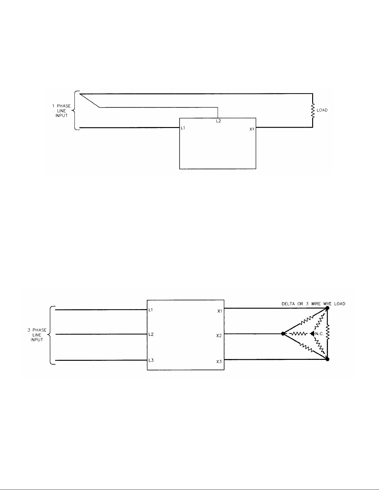
Figure 1 - LINE/LOAD POWER WIRING ZF1 MODELS
Figure 2 – LINE/LOAD POWER WIRING ZF2 MODELS
5
Page 12
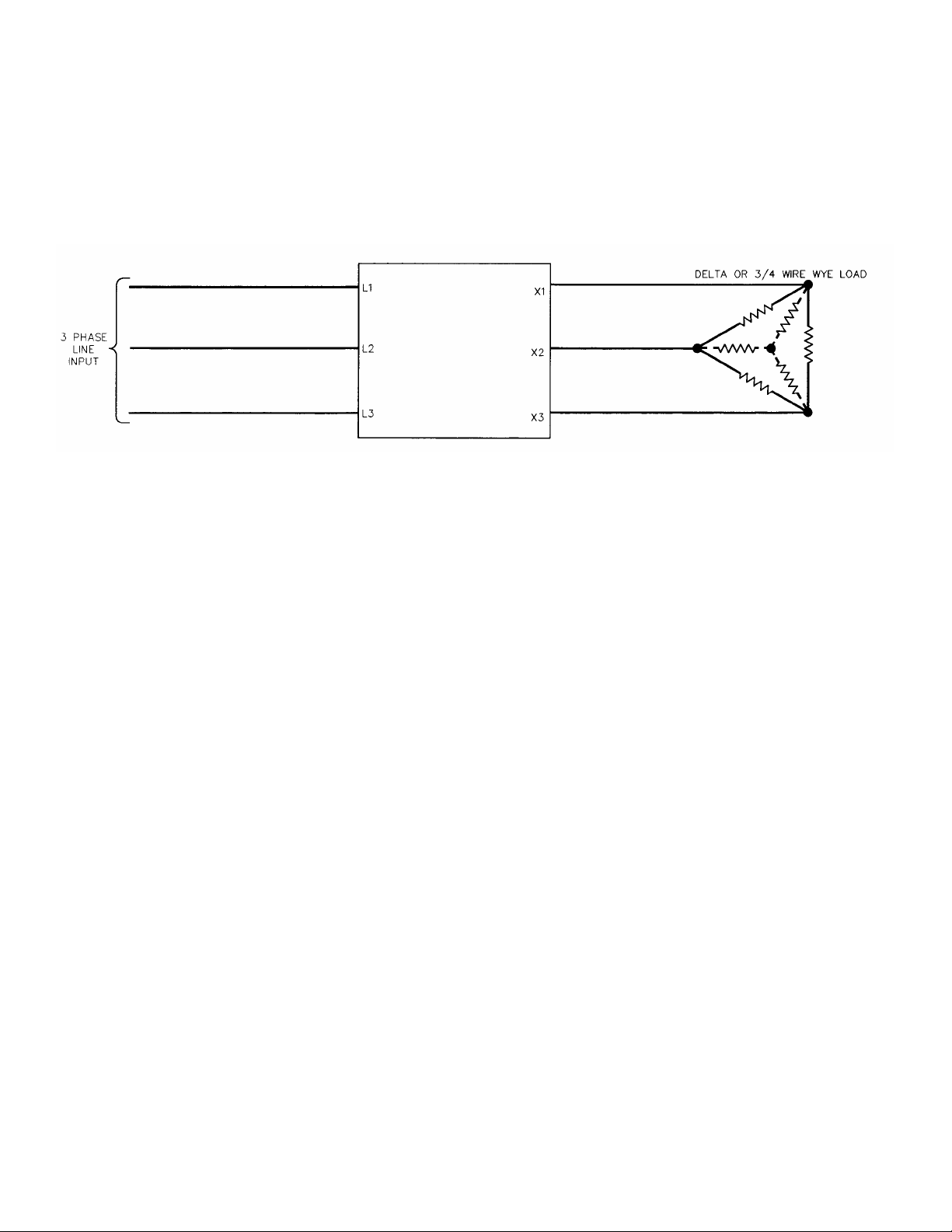
Figure 3 – LINE/LOAD POWER WIRING ZF3 MODELS
6
Page 13

Figure 4 - OUTLINE AND MOUNTING ZF1 60 and 90 through 225 A
7
Page 14

Figure 5 – OUTLINE AND MOUNTING ZF1 350 & 500 A
8
Page 15

Figure 6 – OUTLINE AND MOUNTING ZF1 650 A
9
Page 16

Figure 7 – OUTLINE AND MOUNTING ZF1 800, 1000 & 1200 A
10
Page 17

Figure 8 – OUTLINE AND MOUNTING ZF2 60 and 90 through 225 A
11
Page 18

Figure 9 – OUTLINE AND MOUNTING ZF2 350 & 500 A
12
Page 19

Figure 10 – OUTLINE AND MOUNTING ZF2 650 A
13
Page 20

Figure 11 – OUTLINE AND MOUNTING ZF2 800, 1000 & 1200 A
14
Page 21

Figure 12 – OUTLINE AND MOUNTING ZF3 60 and 90 through 225 A
15
Page 22

Figure 13 – OUTLINE AND MOUNTING ZF3 350 & 500 A
16
Page 23

Figure 14 – OUTLINE AND MOUNTING ZF3 650 A
17
Page 24

Figure 15 – OUTLINE AND MOUNTING ZF3 800, 1000 & 1200 A
18
Page 25

2-3 FAN AND THERMOSTAT WIRING
Fans and thermostats are supplied on all units above 90A. The user is responsible for
supply i ng 120VA C (unl ess otherwise speci fi ed) f or the fan. Ref er to Tabl e 3 f or the f a n
power requi rem en ts b ased on the un i t's c urren t ratin g. Fa n power s houl d b e con n e cte d
to terminals 21 and 22.
.
Normall y Open (NO) thermostats are standard on all uni ts a b ove 9 0A , N orm al ly Closed
(NC) thermostats may be specified. Normally Open or Normally Closed may be
specified on the 60A model as an option. Thermostats are on terminals 23 & 24.
Figure 16 – FAN and THERMOSTAT TERMINALS
CAUTION
The application of fan power should precede or
coincide with the turn-on of the line voltage
source that is to be c ontr oll ed by the disc onnect
switch.
19
Page 26

Table 3 – Fan Power Requirements
Model ZF1
Rating Power Requirements
60A N/A
90A .21A, 25VA (50 Hz.); .19A, 23VA (60 Hz.)
120A .21A, 25VA (50 Hz.); .19A, 23VA (60 Hz.)
180A .21A, 25VA (50 Hz.); .19A, 23VA (60 Hz.)
225A .21A, 25VA (50 Hz.); .19A, 23VA (60 Hz.)
350A .21A, 25VA (50 Hz.); .19A, 23VA (60 Hz.)
500A .21A, 25VA (50 Hz.); .19A, 23VA (60 Hz.)
650A 1.4A, 168VA (50 Hz.); 1.2A, 144VA (60 Hz.)
800A 1.4A, 168VA (50 Hz.); 1.2A, 144VA (60 Hz.)
1000A 1.4A, 168VA (50 Hz.); 1.2A, 144VA (60 Hz.)
1200A 1.4A, 168VA (50 Hz.); 1.2A, 144VA (60 Hz.)
Model ZF2
Rating Power Requirements
60A N/A
90A .21A, 25VA (50 Hz.); .19A, 23VA (60 Hz.)
120A .21A, 25VA (50 Hz.); .19A, 23VA (60 Hz.)
180A .21A, 25VA (50 Hz.); .19A, 23VA (60 Hz.)
225A .21A, 25VA (50 Hz.); .19A, 23VA (60 Hz.)
350A .42A, 50VA (50 Hz.); .38A, 46VA (60 Hz.)
500A .42A, 50VA (50 Hz.); .38A, 46VA (60 Hz.)
650A 2.8A, 336VA (50 Hz.); 2.4A, 288VA (60 Hz.)
800A 2.8A, 336VA (50 Hz.); 2.4A, 288VA (60 Hz.)
1000A 2.8A, 336VA (50 Hz.); 2.4A, 288VA (60 Hz.)
1200A 2.8A, 336VA (50 Hz.); 2.4A, 288VA (60 Hz.)
Model ZF3
Rating Power Requirements
60A N/A
90A .42A, 50VA (50 Hz.); .38A, 46VA (60 Hz.)
120A .42A, 50VA (50 Hz.); .38A, 46VA (60 Hz.)
180A .42A, 50VA (50 Hz.); .38A, 46VA (60 Hz.)
225A .42A, 50VA (50 Hz.); .38A, 46VA (60 Hz.)
350A .63A, 76VA (50 Hz.); .57A, 69VA (60 Hz.)
500A .63A, 76VA (50 Hz.); .57A, 69VA (60 Hz.)
650A 4.2A, 504VA (50 Hz.); 3.6A, 432VA (60 Hz.)
800A 4.2A, 504VA (50 Hz.); 3.6A, 432VA (60 Hz.)
1000A 4.2A, 504VA (50 Hz.); 3.6A, 432VA (60 Hz.)
1200A 4.2A, 504VA (50 Hz.); 3.6A, 432VA (60 Hz.)
20
Page 27

2-4 INPUT LINE VOLTAGE CHANGES
All un its a r e s hip pe d w ire d for th e lin e volta ge s p e c ifie d o n th e or d e r. If some o th e r
voltage is required, it is norma lly a simple matter to change it. Ope n the door on the
Power Control and locate transformer T1. Unsolder and move the whi te/black wi re to
the appropriate voltage tap. On newer units (starting Septemb er 2000) DIP switches
have been added for selecting either 50 or 60 Hz. Operation.
2-4 SAFETY ISSUES
The rated o per ational voltage of each power contr oller is shown on its nameplate, ie.
120V, 240V, 400V, 480V, o r 575V. T he power co ntro ller is designed to o perat e
between +10% and –15% of this rated operational voltage in an O ve r V ol tag e C ate gory
III environment.
Hazardous vol tages exist at the power c ontr o ll e r
heat sinks and at the load at all times when the
input voltage is connec ted. This condi ti on ex i st s
even when the controller is set to deliver zero
output.
Power control units are not suitable to
provide isolation due to the use of
semiconductors and other components
that allow a small current to flow from
line to load even when the unit is in the
non-conducting mode.
WARNING
WARNING
21
Page 28

The voltage drop across the switching semiconductor while in the conducting mode is
approxim ately 1.5 volts and is some what a functi on of current. To calculate the power
control’s power loss, multiply the load current times 1.5 time the number of controlled
phases.
T he minimu m o per at ion al cu rr ent is a pp ro ximat ely 1 A and t he max imum o ff sta t e
cur rent is ap proximately 15 ma.
The power controllers descri be d i n thi s instruction man ual are desi gned to operate in a
pollution degree 2 environment.
HAZARDS EXIST
DANGEROUS VOLTAGES EXIST
22
Page 29

Section 3 – COMM AND SIGNAL CALIBRATION AND WIRING
3-1 ZERO AND SPAN ADJUSTMENTS
All ZF series SCR Power Controllers have both Zero and Span potentiometers used f or
matching the SCR Power Contr ol and the Command Signal. The Zero co nt r ol is for
the low end input (min. output) adjustments while the Span Control is used for the high
end input (max. output) .
The Zero control has both negative and positive voltages available making i t usabl e as a
manu al o r z er o c on tr ol. By t ur ning the co nt ro l clo ck wise , t he ou tp ut will incr ea se
prop ortion ally to the ad jus tment. Tu rn in g it counter-clock wis e w ill de crease or zero
the output.
The Span control is used to adjust the maximum desired output. It will adjust for either
a remote manual control or a command signal input. Clockwise adjustment increases
the output while counter-clockwise adjustment decreases the output.
3-2 COMMAND INDICATOR
The Command Indicator is a green Light Emitting Diode (LED) located on t he front
cove r of the u n it. T h e b r illia n c e of th is L E D w ill c h a ng e w ith the C omma n d Sig n a l.
The brilliance increases with an increased Command Signal and decreases with a
decreased Command Si gnal . The LED is us uabl e with 4-20m a Comm and Si gnal s only
and w ill be b ypassed for other signals.
3-3 ISOLATED AND NON-ISOLATED INPUTS
The Firing Circ uit has the capa bility o f having e ither a n optica lly isolat ed o r nonisolated Command Signal input. The Power Controller will always be shipped with an
isolated i nput unl ess speci fi ed otherwise (known excepti on is a M anual Control input.)
The standard input i mpedan ce i s 500 ohms f or isol ated and 1500 oh m s f or n on -i s ol ate d.
An i solated in put can be chan ged to a non-isolated in put by un solderi ng j umpers J 1 an d
J2 on t he firing circuit and moving them to t he non-isolated position on the firing
circuit. On newer units (starting September 2000) DIP Switch 1 replaces J1 & J2.
The isol ated input works best with an off set Comman d Signal su ch a s 4-20 m a how ev er ,
it will work with both offset and zero based Command Signals. Zero based Command
Signals may have a small amount of non-linearity (input to o utput) at the
lo w e nd. This normally is not a prob lem on closed loop s ystems.;
23
Page 30

3-4 REMOTE MANUAL CONTROL
Some appli cations onl y require a m anual control input and n ot a closed loop in put f rom
a process contr oller. The power contro ller is designed to accept a remote manual
contro l input (refer to Figure 17 for connections.)
Adjus tments are sim pl e and qui ck, but fi rst verif y that the fi ri ng ci rcuit is s et up f or n on isolated input and t hat R6 on the ZF1, R7 on the ZF2 or R5 on the ZF3 has been
removed. On n ewer un its (starting September 2000) DIP Swi tch 2 has been added to
make this conversion easier. Make sure it is in the 1.5K position. Next start with the
Remote Manual Control in the zero (counter-clockwise) position, appl y power to the
Power Control. Adjust the Zero Control so the Power Control's output just starts to
come on, then adjust it count er - clockwise so the unit's output is at zero. Now adjust
the Re m ote Ma nu al Control to th e f ul l output (c l ock wi s e) pos i ti on , a n d a d just t h e S p a n
Control unti l the maximum desired output is reached. This procedure may have to be
repeated due t o some interaction between the Zero and Span controls.
Figure 17 – REMOTE MANUAL CONTROL
NO TE : Us e voltmete r to monitor the ou tpu t voltag e , flic k e ring is c ommon a t any
setpoint ot her than zero or full output. So me load must be present when
making adjustments or taking voltage measurements.
24
Page 31

3-5 PROCESS COMMAND SIGNAL
Process command si gnal s can b e ei ther offset or zero based as discussed earl i e r. S i m pl y
conne ct the c om m a n d sign al to termi n a l s 1 (-) an d 2 (+) on th e f iri n g circui t an d adjust
the Zero and Span controls. Adjustments are easy. Simply have the process
controller's output set at minimum and adjust the Zero control so the unit's output is at
zero. Next have the pro cess contro ller's output set at maximum and adjust the Span
control for the max imum desir ed outp ut. As with the Re mote Ma nual Control, some
interaction between controls does exis t so repeating this procedure may be n ecess ary.
3-6 AUTO/MANUAL CONTROL
On closed l oop processes it m ay b e desi rable to be abl e to operate the power controll er
manually. The HDR power controller has this capability designed into it. Connect the
Command Signal, a Remote Manual contro l and an Auto/Manual switch as shown in
Figure 18. Make adjustments as stated for the Process Command Signal with the
Auto/Manual switch in the Auto position. By switching to the Manual position, the
Remote Manual control operates.
Figure 18 – AUTO/MANUAL CONTROL
NOTE: Some non-linearity will occur with the Manual Control.
25
Page 32

3-7 ON/OFF CONTROL
Some applications require that a simple ON/OFF type contro l be used. The power
controll er can be used i n these si m pl e appli cations. It can be connected for turn on by a
contact closure.
For on/off control, wire the contact according to figure 19. Once the wiring is
complete, turn on the input power. Set the input contact to open and adjust the Zero
control clockwise until the unit comes on, then adjust counter-clockwise until the unit
just shuts off. Now set the input contact t o t he closed position and adjust the Span
control clockwise until the unit's output is at the desired maximum output level.
Repeating of this procedure may be necessary due to some interact ion between the
Zero and Span contro ls.
Figure 19 - ON/OFF CONTROL
3-8 SHUTDOWN (Disable)
26
Page 33

When it is necessary to shutdown or disable the output, it is a simple matter. Connect a
dry contact closure between terminals 3 and 4 of the firing circuit. When it is closed,
t h e p owe r co ntr ol will be shut off.
Figure 20 – FIRING CIRCUIT TERMINALS & DIP SWITCHES
27
Page 34

4-1 ENVIRONMENTAL CONCERNS
Always verify that the SCR Power Controller is mounted in a clean, dust free
environment. Clean the heat sink(s) and printed circuit board periodically so no dust
and/or dirt accumulates on the unit. Dust and/or dirt on the heat si nk fins can prevent
proper airflow causi ng overheatin g of the sem iconductors. Conductive dus t a nd /or di rt
can cause shorts or arcing, which can cause damage to the unit.
Always size your enclosure so t hat a 50 °C maximum internal ambient temperature is
never exceeded.
DISCONNECT ALL SOURCES OF POWER TO THE POWER
CONTROLLER PRIOR TO CLEANING. THE UNIT I S N OT SUI TAB LE FO R
HOSE DOWN CLEANING. USE VACUUM , BRUSH OR LOW PRESSURE
AIR.
4-2 LINE/LOAD POWER CONNECTIONS
Periodically turn the power off to the SCR Power Controlle r a nd che c k for corrosion
and tightness of the power connections. If an y corrosion is ev iden t, clean the cab l e a n d
connector and reconnect maki ng sure to tighten according to our torque specificati ons
in Table 2.
4-3 STATIC PRECAUTIONS WHEN SERVICING
When servici ng the Fi ring Ci rcuit Prin ted Circui t Board (PCB), damage can occur due
to static electricity. Alway s use a wrist strap grounded through a 1 megohm resi stor.
Tr a nsp o rt t he PC B in a st a tic sh ield ing b ag . C au t io n in ha nd ling t he P CB c an help
prevent any further damage to t he PCB.
If you are not familiar with static precautions, consult the factory f or additional detai ls .
4-4 TROUBLESHOOTING TYPICAL SYMPTOMS
Any on e of the follow in g s ymp toms u s u a lly in d ic a te a p r ob le m w ith th e S C R P owe r
Controller.
Section 4 - MAINTENANCE
WARNING
28
Page 35

1. No output regard less of the input.
2. Full output regar dless of the input.
3. Outp ut is no t varia b le from zer o to full.
Refer to Ta ble 4 for help in tr ou bles hooting.
Table 4 - TROUBLESHOOTING
Cause Solution
1 . Open Fuse Disconnect power and check the fuse. Replace if
faulty. If not, contact the factory.
2 . Shorted SCR Disconnect power and check the SCRs. Measure
the resistance across the pair of SCRs (the load
must be disconnected ) , the r esista nce should be
infinite in both directions. If a short is indicated,
replace the defective SCR or return the unit to the
factory.
3. Defective Firing Circuit Disconnect power and unplug the Firing Circuit.
Order a replacement or return t he Po wer Contro ller
to the factory.
NOTE: Virtually any failures of SCRs or Fuses on Zero-Fired equipment can be
attr ibuted to short circuits in the load or loose power connections that cause
arcing or sparking.
Always disconnect the power source
prior to attempting to service the
equipment.
WARNING
29
Page 36

Section 5 - SERVICE AND SPARE PARTS
5-1 CUSTOMER SERVICE
If you have operational problems which cannot be resolved using this manual, please
contact the Service Department at AMETEK HDR. Our normal work hours are 8
a.m. to 5:00 p.m., U.S.A. EASTERN TIME ZONE, Monday through Friday.
TELEPHONE: 1-888-PWR-CNTL (797-2685) OR 614-308-5500.
Our answering machine at 614-308-5500 will answer after hours and we will return
your call the next working day.
FAX: 614-308-5506. 24 hours per day automatic answering.
5-2 SPARE PARTS
Inside Sales should be contacted for any spare parts orders whether routine or
emergency during normal working hours. All after hours requirements should be
call ed in on our 614-308-5500 answering m achi ne. Pleas e have as much in formati on
avail abl e as possi bl e pertaini ng to the model num ber, serial num ber , ord er nu m b er an d
parts required. A purchase order number should be available.
5-3 WARRANTY
AMETEK HDR warrants that the equipment delivered will be fr e e from d e fe c ts in
workmanship and material for a period of five years from the date of shipment.
AMETEK HDR will re p air o r r e p lace, at AMETEK HDR's option, any part found
defectiv e duri ng proper and normal use, provi ded that written notice of the nature of
the defect is recei ved by AM ETEK HD R wi thi n the f i v e y ear w arran ty per i od a n d th at
the customer returns the part to AMETEK HDR freight paid both ways. This
war ranty is not tr ansferable by the initia l end u se r.
AMETEK HDR MAKES NO OTHER WARRANTIES, EXPRESSED OR
IMPLIED (INCLUDING, WITHOUT LIMITATION, MERCHANTABILITY,
FITNESS FOR PURPOSE, OR AGAINST INFRINGEMENT OF ANY PATENT)
EXCEPT AS EXP RE SS LY PROVI DE D HE RE IN.
THE REMEDY OF R EPAIR OR R EPLA CEMEN T IS CUSTO MER' S SOL E A ND
EXCLUSIVE REMEDY AND WILL SATISFY ALL OF AMETEK HDR'S
LIABILITIES, WHETHER BASED ON CONTRACT, NEGLIGENCE, TORT,
PRODUCT LIABILITY, STRICT LIABILITY, OR OTHE RWI SE. IN N O EVEN T
WILL AMETEK HDR BE LIABLE FOR INCIDENT OR CONSEQUENTIAL
DAMAGES, NOR IN ANY EVENT SHALL AMETEK HDR'S LIABILITY
EXCEED TH E UNI T P RI CE OF ANY DEFECTIV E P RODUCT OR PART.
30
Page 37

EC DECLARATION OF CONFORMITY
WE: AMETEK HDR POWER SYSTEMS
3563 Interchange Road
Columbus, Ohio 43204 - USA
Declare under our sole responsibility that the products listed below and bearing the CE label:
Type: SCR power controllers with the following model designations and current ratings:
ZF1, ZF2, ZF3, PF1, PF3 - 15, 25, 40, 60, 70, 90, 120, 180,
225, 350, 500, 650, 800, 1000 and 1200A.
SHZF1, SHPF1 - 15, 30, 40, 60, 70, 90 and 120A
SHZF2, SHZF3, SHPF3 - 15, 25, 30, 60, 90, 120, 180 and 225A
SCZF1, SCPF1 - 15, 25, 40 and 65A
To which this declaration relates is in conformity with the technical requirements of the following
documents:
Title: Low-voltage switchgear No. IEC 947-5-1
and controlgear Year: 1990-03
Low Voltage Directive No. IEC 73/23/EEC
Year: 1973-02
Degrees of protection provided No. IEC 529-2nd Edition
by enclosures (IP Code): Year: 1989-11
Electromagnetic Compatibility No. IEC 89/336/EEC
(EMC) Year: 1989-05
Warning
All phase-fired (PF) controllers will require line filters and
possibl y shielded cables to meet the EMC requirements .
(Environmental protection classification IP00 - for mounting inside an
enclosure)
Note
: Characteristics are according to manufactures specifications.
Name: George A. Sites
Title: Vice President
Date: November 10, 2000
Declaration written in accordance with I.S.O. - IEC/22 Guide
31
 Loading...