

Page 1

GENERAL INSTALLATION, OPERATION AND MAINTENANCE INSTRUCTIONS
FOR FURNACES
TABLE OF CONTENTS
1 SHIPPING DAMAGE & HANDLING
2 PROPER FURNACE APPLICATION
2-1 General
2-2 Flammable Solvents
2-3 Combustible Material
2-4 Personnel Hazards
2-5 Maintenance and Inspection
3 INSTALLATION
3-1 Location
3-2 Building Considerations
3-3 Clearances
3-4 Ventilation
3-5 Exhaust Ductwork
3-6 Fuel Gas Supply
3-7 Electrical
4 PRIOR TO PLACING FURNACE IN SERVICE
5 PROCESSING
6 SAFETY EQUIPMENT
7 MAINTENANCE
8 TROUBLE SHOOTING
9 APPENDIX A - SAFETY EQUIPMENT, DESCRIPTION & OPERATION
10 APPENDIX B - REFERENCES
11 APPENDIX C - MINIMUM PERIODIC MAINTENANCE REPORT
12 APPENDIX D - SAFETY SHUT OFF VALVE LEAK TEST PROCEDURE
13 APPENDIX E - WARRANTY AND LIMITATIONS OF REMEDIES
Following these GENERAL INSTRUCTIONS in your manual are the following:
-OPERATING INSTRUCTIONS SPECIFIC FOR YOUR EQUIPMENT
-MECHANICAL PARTS LIST
-ELECTRICAL WIRING AND COMPONENT PARTS LIST
-LITERATURE AND INSTRUCTIONS ON COMPONENTS
These GENERAL INSTRUCTIONS have been written for many different types of furnaces,
therefore, some equipment or components referred to may not be present on your particular
piece of equipment.
After reading these GENERAL INSTRUCTIONS, also read the specific OPERATING
INSTRUCTIONS written for your equipment. An additional copy of the OPERATING
INSTRUCTIONS is provided in a plastic cover. Post these instructions at the furnace for the
operator to reference.
W:\ELECTRICAL\INSTRUCT\FURNACE\FURNACE GENERAL INSTRUCTIONS 2011.DOC 1 of 36 01/2014
Page 2

1 SHIPPING DAMAGE AND HANDLING
DO NOT RETURN DAMAGED MERCHANDISE TO US.
FILE YOUR CLAIM AS OUTLINED BELOW
This merchandise has been thoroughly inspected and carefully packed before leaving our
plant. Responsibility for its safe delivery was assumed by the carrier at the time of shipment.
Claims for loss or damage to the contents must be made with the carrier, as follows:
1-1 VISIBLE LOSS OR DAMAGE
Any external evidence of loss or damage must be noted, at the time of delivery, on the freight
bill or express receipt and signed by the carrier's agent. Failure to adequately describe such
external evidence of loss or damage may result in the carrier refusing to honor a damage
claim. Make a written request for inspection by the carrier's agent within fifteen days of the
delivery date. Review the inspection report and do not sign it unless it adequately describes
the damage.
A claim must be filed with the carrier since such damage is the carrier's responsibility.
1-2 CONCEALED LOSS OR DAMAGE
Concealed loss or damage means loss or damage which does not become apparent until
the merchandise has been unpacked. The contents may be damaged in transit due to rough
handling even though the carton may not show external damage. When the damage is
discovered upon unpacking, contact the carrier and make a written request for inspection by
the carrier's agent within fifteen days of the delivery date. Review the inspection report and
do not sign it unless it adequately describes the damage.
A claim must be filed with the carrier since such damage is the carrier's responsibility. By
following these instructions carefully, we guarantee our full support of your claims to protect
you against loss from concealed damage.
1-3 RETURNING DAMAGED EQUIPMENT
Damaged equipment will not be accepted at our factory unless we have been advised and
instructions provided on how it should be returned. A copy of the freight claim must be
provided prior to returning the equipment.
1-4 HANDLING
After inspection, store and handle all equipment and components in their original crates until
ready for installation. Handle with care. The equipment may be heavy but some
components are of a delicate nature. If the equipment is to be stored, keep it in the original
crates and store in a location free from excessive dust, heat and moisture until ready for
installation.
W:\ELECTRICAL\INSTRUCT\FURNACE\FURNACE GENERAL INSTRUCTIONS 2011.DOC 2 of 36 01/2014
Page 3

2 PROPER FURNACE APPLICATION
2-1 GENERAL
2-1.1 While furnaces are extremely versatile, they are usually purchased with a specific
application in mind. If your process has changed significantly or if you should have
reason to doubt that a specific application is a proper use of the equipment, consult
the factory before proceeding.
2-1.2 Explanatory Material (Annex A1.1) of the National Fire Protection Association
Publication 86 "Standard for Ovens and Furnaces" states; in part:
"Explosions and fires in fuel-fired and electric heat utilization equipment constitute a
loss potential in life, property and production.”
Most failures can be traced back to human error. The most significant failures
include inadequate training of operators, lack of proper maintenance, and improper
application of equipment."
2-1.3 To protect the furnace, furnace contents, property and personnel, a responsible
person should be in attendance during operation. Do not operate furnace
unattended. Special attention must be paid to:
-Setting correct temperature.
-Placing flammable solvents in a furnace not designed for that
purpose.
-Placing combustibles in a furnace that does not have adequate fire
protection.
-Allowing the product to remain in the furnace too long, thereby
encouraging combustion.
-Using a furnace for a process other than that for which it was designed.
2-1.4 Furnace operator should shut down the furnace immediately and notify their
supervisor if there are changes in furnace performance, a safety interlock trips or,
in the case of fuel fired equipment, the smell of natural gas or propane is present.
The furnace should not be put back into production until the causes are found and
corrected.
2.2 FLAMMABLE SOLVENTS
2-2.1 Processing solvents in a non-solvent furnace, exceeding the design temperature, or
exceeding the maximum amount of solvent allowed in a furnace, could result in fire
or explosion and bodily injury or property loss.
If flammable solvents or vapors will be present in a furnace, the Occupational
Safety & Health Administration (OSHA) requires that it have a separately powered
forced exhauster of adequate size and other related safety devices not supplied as
standard equipment. Furnaces designed for this purpose have a caution plate and
Furnace Design Data Form showing the maximum gallons of solvent, or pounds of
powder coating, and the maximum operating temperature for which that specific
furnace has been designed. If in doubt, consult factory for details.
2-2.2 It shall be the user's responsibility to ensure that the amount of flammable solvent
placed in the furnace and the operating temperature does not exceed the design
capacity -- see Safety Design Form and furnace caution nameplate.
W:\ELECTRICAL\INSTRUCT\FURNACE\FURNACE GENERAL INSTRUCTIONS 2011.DOC 3 of 36 01/2014
Page 4

2-2.3 In areas outside of the furnace where flammable solvents are given off by material
prior to entering the furnace, provisions should be made to exhaust these vapors to
atmosphere to prevent them from being pulled into the furnace or collecting and
creating a flammable mixture.
2-3 COMBUSTIBLE MATERIAL
2-3.1 Introduction of combustible materials (such as paper, cardboard or wood) into the
furnace should be avoided because it might cause a fire. Do not use combustible
racks, trays, holders, spacers, etc. Periodically, clean all combustible material from
non-combustible racks, trays, holders, spacers, etc. If combustible products must
be processed in a furnace, extreme care must be taken to ensure that the operating
temperature does not exceed the ignition temperature of the product.
2-3.2 Furnaces containing or processing sufficient combustible materials (including
consideration for combustible drippings or deposits) to sustain a fire shall be
equipped with an automatic fire protection system including areas in exhaust ducts
that could accumulate combustible material. Fire protection systems should be
installed in accordance with the applicable National Fire Protection Guidelines:
-Sprinkler Systems in accordance with NFPA 13
-Water Spray Systems in accordance with NFPA 15
-Carbon Dioxide Extinguishing Systems in accordance with NFPA 12
-Foam Extinguishing Systems in accordance with NFPA 11
-Dry Chemical Extinguishing Systems in accordance with NFPA 17
-Water Mist Systems in accordance with NFPA 750
The extent of protection required will depend upon the construction and
arrangement of the furnace as well as the materials handled. Fixed protection,
such as automatic sprinklers or other types of fire extinguishing systems, should be
designed and installed by a qualified contractor.
2-3.3 Drip pans shall be provided to collect any combustible materials that may
accumulate beneath the product. A maintenance program must be developed to
remove any such accumulation before a substantial build-up occurs that could
spontaneously ignite and cause a fire. If you cannot acquire drip pans locally,
contact us for a quotation.
2-4 PERSONNEL HAZARDS
2-4.1 You must analyze your use of this equipment and determine if it creates a confined
space hazard, as defined by OSHA, in your work place. You are responsible for
posting appropriate warnings and complying with applicable OSHA STANDARDS
pertaining to confined space hazards. (Reference ANSI Z117-1 ASafety
Requirements for Confined Spaces@, see Appendix B)
2-4.2 If inert atmospheres are to be used, keep in mind that inert gases displace air and
create oxygen-deficient atmospheres. For this reason, they can cause suffocation.
Moreover, some inert gases, such as argon, are heavier than air and can collect in
low lying or sealed areas creating oxygen-deficient pockets within the work place.
Use inert atmospheres only in large work places with good ventilation. Do not
breathe in or enter an inert atmosphere piece of equipment until it has been
thoroughly purged with air.
W:\ELECTRICAL\INSTRUCT\FURNACE\FURNACE GENERAL INSTRUCTIONS 2011.DOC 4 of 36 01/2014
Page 5

2-4.3 Heat processing equipment must always be used with caution. Proper equipment
such as insulated gloves, safety goggles and tongs should be used for reaching
into hot equipment. Proper supervision is essential and only trained personnel
should be allowed to operate the furnace.
Always remember you are working with elevated temperatures.
-Do not touch surfaces - they could be hot and burns could result.
-Do not breathe hot furnace air. Heated air could burn lungs.
-Many items become dangerous when heat is applied. Explosion or fire
could result. Make sure you know what you are putting in the furnace can
be heated safely at the furnace operating temperature.
2-4.4 Furnace heating elements operate at line voltage. Do not touch them or allow
work to come in contact with the heating elements. A door interlock is provided to
disconnect power from heating elements when the door is opened. Do not defeat
the operation of this door interlock.
2-5.5 Disconnect power before servicing equipment. Furnaces operate under high
voltage and electrical shock is possible. Proper panel lockout procedures should
be followed.
2-4.6 Disconnect other sources of potential energy such as compressed air, before
servicing. Proper lockout procedures should be followed.
2-4.7 Do not operate mechanical or electrical equipment with guards removed.
Operating with guards removed could result in bodily injury.
2-4.8 Furnaces with vertical lift doors or top loading doors must be blocked open before
passing beneath them. A falling door may cause bodily injury. A safety pin, latch or
support strut is provided for this purpose.
2-5 MAINTENANCE AND INSPECTION
2-5.1 Regularly scheduled inspection and maintenance of all safety devices shall be
performed by user. Failure to do this may result not only in fire or explosion
damage, but also contribute to accidental shutdowns and loss of production. See
Section 7 - Maintenance and Appendix C - Minimum Periodic Maintenance Report.
2-5.2 Regularly scheduled inspection of the furnace interior, heat chamber and ductwork
shall be performed by user to determine need for cleaning and repair. Failure to do
this may result in internal fires or component failure resulting in furnace damage
and loss of production.
2-5.3 It shall be the sole responsibility of the user to establish, schedule and enforce the
frequency of and the extent of the inspection/maintenance program (as well as the
corrective action to be taken) because only the user can know what the actual
operating conditions are. Contact your insurance authority, Factory Mutual or the
National Fire Protection Association, whose addresses are listed in Appendix B, for
more information on inspection/maintenance programs.
2-5.4 It shall be the responsibility of the end user to determine that current processing is
within the scope of the original design of the equipment.
W:\ELECTRICAL\INSTRUCT\FURNACE\FURNACE GENERAL INSTRUCTIONS 2011.DOC 5 of 36 01/2014
Page 6

2-6 RETROACTIVITY
This equipment has been designed and manufactured in accordance with applicable
National Codes in effect as of the date of manufacture. It is the responsibility of the end user
to update equipment as necessary to comply with future code changes. If you are in doubt,
contact manufacturer to review your equipment design against current National Codes.
W:\ELECTRICAL\INSTRUCT\FURNACE\FURNACE GENERAL INSTRUCTIONS 2011.DOC 6 of 36 01/2014
Page 7

3 INSTALLATION
3-1 LOCATION
3-1.1 Furnaces shall be located to protect them from damage by external heat, vibration
and mechanical hazards.
3-1.2 Furnaces shall be located to make maximum use of natural ventilation, to minimize
restrictions to adequate explosion relief, and to provide sufficient air supply for
personnel. Room volume should be at least 10 times the furnace volume.
3-1.3 Furnaces shall be located to minimize exposure to power equipment, process
equipment and sprinkler risers. Unrelated stock and combustible materials shall be
maintained at a fire-safe distance but not less than 10 feet from a furnace, a
furnace heater or ductwork.
3-1.4 Furnaces shall be located to minimize exposure to people from the possibility of injury
from fire, explosion, asphyxiation, and hazardous materials and shall not obstruct
personnel travel to exit ways.
3-1.5 If the furnace control panel is located away from the furnace, operators must be
allowed access to the control panel and/or main disconnect to allow them to shut
down the furnace in an emergency.
3-1.6 Furnaces shall be located to prevent an ignition source to flammable coating dip
tanks, spray booths and storage and mixing rooms for flammable liquids and to
prevent exposure to flammable vapor or combustible dust clouds. Furnaces should
not be located in hazardous (classified) locations unless they are designed to
comply with the applicable requirements of NFPA 70 ANational Electric Code@
(see Appendix B).
3-1.7 Equipment shall be protected from corrosive external processes and environments,
including fumes or materials from adjacent processes or equipment that produces
corrosive conditions when introduced into the furnace environment.
3-1.8 The furnace is not intended for outdoor installation and must be sheltered from
weather. Unheated shelters may result in non-uniform temperatures or insufficient
heat to attain maximum operating temperature. Condensation may also occur
which would be detrimental to the steel structure and electrical components.
3-1.9 Suitable portable fire extinguishers should be available and operators trained in their
use. All such fire protection equipment should be inspected periodically in
accordance with appropriate standards. Reference NFPA 10 AStandard for
Portable Fire Extinguishers@ (see Appendix B).
3-2 BUILDING CONSIDERATIONS
3-2.1 When selecting the location for a furnace, consideration must be given to the
possibility of fire, building damage and personal injury. Hazards to be considered
include overheating of material in the furnace and escape of fuel gas or exhaust
into the work place.
3-2.2 Furnaces shall be located and erected so that the building structural members are
not affected adversely by the maximum anticipated temperature or by the additional
loading caused by the furnace and load.
3-2.3 Furnaces should be placed on noncombustible floors or on structures approved for
use over combustible floors such as concrete floor slabs or hollow tiles.
W:\ELECTRICAL\INSTRUCT\FURNACE\FURNACE GENERAL INSTRUCTIONS 2011.DOC 7 of 36 01/2014
Page 8

3-2.4 Level the furnace using shims, if necessary. Where mounting holes are provided,
anchor the furnace securely. Shims should be permanently mounted to the furnace
after installation.
3-3 CLEARANCES
3-3.1 Furnaces shall be located with adequate space above and on all sides to allow for
inspection, maintenance and operator access. Provisions also shall be included for
unobstructed discharge of building sprinklers, the installation of automatic fire
protection system within the furnace, if necessary and the proper functioning of
explosion relief doors and panels.
3-3.2 Do not place the furnace up against a wall. A minimum air space of 12 inches must
be provided on all sides to allow for air circulation, with additional space being
provided for furnaces operating over 1400°F (760°C) to keep temperature at
adjacent structures and materials below 160°F (70°C). Local, city and state codes
may specify building requirements and special provisions for locating furnaces.
3-3.3 The furnace should be located so there is unrestricted air circulation around all
motors for proper cooling.
3-3.4 Do not store material on top of furnace. The furnace is not designed to support
external loads and material may get hot, ignite and cause a fire.
3-3.5 To prevent ignition of combustible material, combustible material shall be located at
a safe distance from furnace and furnace ductwork. The National Fire Protection
Association (NFPA) Standard 86 specifies a minimum distance of 2-1/2 feet;
Factory Mutual (FM) specifies at least 10 feet.
3-3.6 The furnace door travel must not be restricted and should face away from main
aisles, work areas and automatic sprinkler risers, feeds and cross mains.
3-4 VENTILATION
3-4.1 Where furnaces are located in basements or enclosed areas, sufficient room
ventilation shall be supplied to provide required combustion air for fuel fired
equipment and to prevent the hazardous accumulation of vapors from processing.
3-4.2 Furnaces designed for use with fuel gas or process gas having a specific gravity
greater than air (such as propane) shall be located at or above grade and shall be
located to prevent the escape of the fuel gas from accumulating in basements, pits,
or other areas below the furnace.
3-4.3 Fresh air inlets and exhaust outlets (if applicable) must never be restricted. If
filtered air is provided, there must be adequate filter capacity to prevent any
reduction in airflow even under adverse loading of the filter. The filters must be
periodically inspected and replaced as required.
3-4.4 A sufficient quantity of building make-up air should be admitted to furnace rooms
and buildings to provide the air volume required for furnace safety ventilation and
adequate combustion air for fuel fired equipment. Buildings should not operate
under a negative pressure.
W:\ELECTRICAL\INSTRUCT\FURNACE\FURNACE GENERAL INSTRUCTIONS 2011.DOC 8 of 36 01/2014
Page 9

3-4.5 Some furnaces are equipped with an exhaust outlet. This outlet must be vented by
an exhaust flue to an exhaust stack for discharge to an outside location, in
accordance with local codes and requirements. Do not connect exhaust outlet
directly to exhaust stack. Exhaust gas temperature is the same as internal furnace
temperature. Reduce exhaust temperatures by diluting with room air before
ducting to the outside. Caution must be taken to protect combustible building
materials from coming in contact with the hot exhaust stack.
3-4.6 The minimum safe exhaust rate must be confirmed for furnaces equipped with a
powered forced exhauster to handle flammable solvent vapors or products of
combustion from fuel fired equipment. The exhaust rate has been set at the factory
and dampers cut off and screwed in place or in some other manner limited to
prevent exhaust rate from being reduced below safe minimum exhaust rate.
After installation, this exhaust rate must be confirmed. This must be done at the
outlet of the stack from the building. The exhaust rate must meet or exceed the
minimum rate indicated on the Safety Design Form located on the side of the
furnace. If it is necessary to open the exhaust damper to increase the exhaust rate,
it must be cutoff or locked in position to prevent accidental closing.
Exhaust rate must be checked again if any changes are made to ventilation
system, duct work or building ventilation. Adding additional equipment, which
requires ventilation, to the building will require additional make-up air to the building
to prevent the building from operating under negative pressure. Operating building
under negative pressure will reduce exhaust rate from furnace to below safe
minimum exhaust rate.
Fuel fired furnaces without powered forced exhauster must have unrestricted
negative pressure (room not under negative pressure) stack to remove products of
combustion from work area.
3-4.7 For additional ventilation information, refer to NFPA 31 AStandard for the
Installation of Oil-Burning Equipment@, NFPA 54 ANational Fuel Gas Code@ and
NFPA 91 AStandard for Exhaust systems for Air Conveying of Vapors, Gases,
Mists and Noncombustible Particulate Solids@ (see Appendix B).
3-5 EXHAUST DUCTWORK
3-5.1 Wherever furnace ducts or stacks pass through combustible walls, floors, or roof,
either non-combustible insulation or clearance, or both, shall be provided to prevent
combustible surface temperatures from exceeding 160°F (72EC).
3-5.2 Where ducts pass through non-combustible walls, floors or partitions, the space
around the duct shall be sealed with non-combustible material to maintain the fire
rating of the barrier. Ducts that pass through fire walls should be avoided. Local,
city and state codes may apply to duct installation.
3-5.3 Exhausts systems should be installed in accordance with Chapter 1, 2 and 3 of
NFPA 91 AStandard for Exhaust Systems for Air Conveying of Vapors, Gases,
Mists, and Noncombustible Particulate Solids@ (see Appendix B).
3-5.4 Ducts shall be constructed entirely of sheet steel or other non-combustible material
capable of meeting the intended installation and conditions of service. The
installation shall be of adequate strength and rigidity and shall be protected where
subject to physical damage.
W:\ELECTRICAL\INSTRUCT\FURNACE\FURNACE GENERAL INSTRUCTIONS 2011.DOC 9 of 36 01/2014
Page 10

3-5.5 Ducts handling fumes that leave a combustible deposit shall be provided with
clean-out doors and such doors should be equipped with tight fitting doors or
covers. It is important that furnaces and ducts be kept clean if they are subjected
to a build-up of flammable deposits of condensed solvent, oil vapors, dust or other
combustible debris. The build-up of condensed vapors or combustible debris is a
major cause of fires. Frequency of cleaning should be based on never allowing
build-up to exceed 1/8" thickness in any location.
3-5.6 No portions of the building shall be used as an integral part of the duct.
3-5.7 All ducts shall be made tight throughout and shall have no openings other than
those required for the operation and maintenance of the system. All interior laps in
the duct joints should be made in the direction of the flow.
3-5.8 All ducts shall be thoroughly braced where required and substantially supported by
metal hangers or brackets.
3-5.9 Ducts handling flammable vapors shall be designed to minimize the condensation
of the vapors out of the exhaust stream onto the surface of the ducts. One method
is to insulate the ducts. If flammable condensation cannot be avoided, ducts
should be pitched to drain to suitable traps or other safe locations.
3-5.10 Ducts handling combustible solids shall be designed to minimize the accumulation
of solids within the ducts.
3-5.11 Exhaust ducts that will contain combustible deposits of any type require automatic
sprinklers in accordance with NFPA 13 AStandard for Installation of Sprinkler
Systems@ (see Appendix B).
3-5.12 Exhaust ducts shall not discharge near building openings or other air intakes that
allow re-entry of effluents into the building.
3-5.13 Clearance between metal ducts and stored combustible material should be at least
2-1/2 feet. Guards should be installed to assure this clearance.
3-5.14 Multiple exhaust fans manifolded together should have manifold designed so that
operation of one or more exhaust fan does not create a hazard such as back flow
to an idle furnace or reduced exhaust flow due to increased manifold pressure.
3-5.15 Duct work should not include dampers that could be closed and restrict flow within
the duct work.
3-6 FUEL GAS SUPPLY
3-6.1 Piping from the point of delivery to the equipment should comply with NFPA 54,
National Fuel Gas Code. Local, city and state codes should be followed. Gas
source pressure must be less than 60 psig.
3-6.2 A gas filter or strainer and sediment trap with vertical leg (drip leg) at least 3 pipe
diameters long (3" minimum) of same size as supply piping, shall be installed in the
fuel gas supply piping to protect the downstream safety shutoff valves and regulator
from materials that could interfere with their operation.
W:\ELECTRICAL\INSTRUCT\FURNACE\FURNACE GENERAL INSTRUCTIONS 2011.DOC 10 of 36 01/2014
Page 11

3-6.3 All gas heated equipment shall be provided with an individual gas pressure
regulator properly sized to supply the pressure and volume required. The furnace
nameplate lists the gas pressure and the burner capacity. Gas pressure regulator
should have the following characteristics:
a. The regulator must be of the full lock-up type; gas pressure must be regulated
even under no flow condition.
b. Incoming pipe size should not exceed 2" diameter.
c. Self contained with no external static or control piping.
d. Single port with correctly sized orifice for the maximum gas pressure at the
regulator inlet.
e. Valve seat is of resilient material designed to withstand abrasion of gas,
impurity in gas, cutting by the valve and to resist permanent deformation by
the valve port.
f. Capable of regulating downstream pressure under no flow conditions to not more
than 150 percent of the discharge pressure under flow conditions.
If these criteria are not met, a pressure relieving or limiting device is required as
outlined in the NFPA 54 National Fuel Gas Code.
3-6.4 A remotely located emergency manual shutoff valve shall be provided to allow the
fuel to be turned off in an emergency and shall be located so that fire or explosion
at the furnace does not prevent access to this valve. Operators should be
instructed on the location of this valve and allowed access to shut off fuel flow in an
emergency. Valve shall have permanently affixed visual indication of position and
be operable without tools.
3-6.5 An equipment isolation shutoff valve must be provided at each piece of equipment.
Valve shall be quarter turn with stop, permanently affixed visual indication of
position, and operable without tools. Valve handle must remain affixed and be
parallel to pipe when open and perpendicular to pipe when closed.
3-6.6 Regulators and high or low gas pressure switch vent lines shall be piped to a safe
location outside the building according to local codes. Protect outlet from water
entry and provide bug screen.
3-6.7 Vent lines from regulator and switches of a single furnace may be manifolded
together in such a manner that diaphragm rupture of one regulator or switch does
not back load others. The cross section of the vent manifold should be not less
than the area of the largest vent line plus 50% of additional lines.
3-6.8 Vent lines from multiple furnaces shall not be manifolded together.
3-6.9 A normally open vent valve between safety valves shall not be combined with other
vents. Care must be taken to terminate a vent valve line in a safe approved
location.
W:\ELECTRICAL\INSTRUCT\FURNACE\FURNACE GENERAL INSTRUCTIONS 2011.DOC 11 of 36 01/2014
Page 12

3-7 ELECTRICAL
3-7.1 All electrical connections should be made in accordance with the appropriate local
and national codes. Refer to NFPA 70 -- National Electric Code. (See Appendix B)
3-7.2 Properly size the electrical supply using information provided on the furnace
nameplate. Electric supply must include a safety shut off such as a circuit breaker
or fused disconnect switch between your power supply and the equipment.
3-7.3 The furnace must be adequately grounded. Grounding wire must be sized in
accordance with local codes. Where more strict codes do not exist, refer to the
National Electrical Code - NFPA 70. A grounding lug has been provided near the
power input terminals.
3.7.4 Care must be taken during installation of electrical service to the control panel that
metal chips or filings do not get into electrical components. Cover components
when drilling or cutting control panel.
W:\ELECTRICAL\INSTRUCT\FURNACE\FURNACE GENERAL INSTRUCTIONS 2011.DOC 12 of 36 01/2014
Page 13

4 PRIOR TO PLACING THE FURNACE IN SERVICE
4-1 Read instruction manual completely. Additional copies of the Operating Instructions
have been provided in plastic covers for posting at the furnace.
4-2 All furnaces should be dried out before heating to maximum temperature. See
specific drying schedule included in your Operating Manual or follow the general
procedure below:
INSULATION DRY-OUT SCHEDULE
All furnaces will produce smoke and odors when first heated. The smoke and odors
come from three sources:
1) Surfaces that have been painted after test;
2) Binders that remain in the insulation;
3) Moisture that has been absorbed by the insulation.
If during the initial run of the furnace the smoke and odors become objectionable, set
the temperature at 300°F and allow the furnace to remain at 300°F until the smoke is
no longer generated. Increase the temperature in steps until you=ve reached the
maximum operating temperature. It may take several days of running at the
maximum operating temperature to eliminate all smoke and odors.
If the furnace is not heated for an extended time period, moisture may accumulate in
the insulation. When heated, this moisture will e driven out and the above process
may have to be repeated.
The following procedure must be followed prior to placing your furnace in operation:
-After the furnace has been installed, it is ready for initial dry out. Before the
equipment can be put into operation, the refractories must be slowly dried out. The
furnace refractories absorb moisture; if they are heated rapidly, steam will be
generated which can damage the refractories. This is true on initial start-up and after
any prolonged shutdown.
-During initial dry out, organic binders contained in some insulating materials will burn
out. The furnace door must be left slightly open to allow air to enter the work
chamber during dry out to allow these binders to burn out. This will avoid the
formation of carbon deposits in the insulation which could lead to premature heater
terminal failure.
-It is necessary to open the furnace door slightly to allow the moisture and organic
binders to escape. Only a small opening is required. If the door is opened too far,
the door switch will turn off the power to the heating elements.
-If at any of the dry out stages, smoke and moisture continue after the hold period,
continue holding until they stop.
FIRST DAY:
1. With the furnace door slightly open, set the temperature control at 500°F and hold
for two (2) hours or until smoke and moisture no longer escape from the open
door.
2. Increase the temperature to 750°F and hold for four (4) hours or until smoke and
moisture no longer escape from the open door.
W:\ELECTRICAL\INSTRUCT\FURNACE\FURNACE GENERAL INSTRUCTIONS 2011.DOC 13 of 36 01/2014
Page 14

3. Increase the temperature to 900°F and hold for two (2) hours or until smoke and
moisture no longer escape from the open door.
4. Turn off the furnace and allow it to sit overnight with the door slightly open.
SECOND DAY:
1. With the furnace door slightly open, heat the furnace again to 900°F and hold for
two (2) hours or until smoke and moisture no longer escape from the open door.
2. Increase to 1200°F and hold for two (2) hours or until smoke and moisture no
longer escape from the open door.
3. If the furnaces= maximum temperature is 1200°F, hold at 1200°F for two (2)
additional hours or until smoke and moisture no longer escape from the open
door.
4. Increase to 1600°F and hold for 2 hour. Close the furnace door and continue at
1600°F for 1-1/2 hours. At the end of this time period, increase to the maximum
operating temperature anticipated and hold for two (2) hours. If no higher
operating temperature is anticipated, continue to run at 1600°F for two (2) hours
or until smoke and moisture no longer escape from the open door.
4-3 The excess temperature limit interlock should be connected to your alarm system.
The wiring schematic indicates where the alarm relay should be located for this alarm
circuit.
4-4 After the installation is completed, replace all doors, covers and guards that had been
removed for shipment or installation. At no time should equipment be operated if
covers or guards are open, removed or partially closed.
4-5 When the equipment is placed in operation, check all blowers for proper rotation.
Rotation directional arrows are located near each blower. Three phase motors may
be reversed by interchanging any two (2) of the three (3) wires which supply power to
the furnace. Do not switch leads at the motor starter or motor. Single phase motors
are correctly set at the factory but correct rotation should still be confirmed.
4-6 The exhaust rate must be checked on furnaces equipped with a powered forced
exhauster to handle flammable solvent vapors or products of combustion from gas
heated equipment. This must be done at the outlet of the furnace before the exhaust
enters the flue. It must meet or exceed the minimum rate indicated on the Furnace
Design Data Form located on the side of the furnace. If it is necessary to open the
exhaust damper to increase the exhaust rate, it must be cutoff or locked in position to
prevent accidental closing.
4-7 Check incoming voltage against that shown on the nameplate.
4-8 Check operating current against the amperage shown on the nameplate.
4-9 On gas heated equipment, purge gas line to furnace of all air and check gas pressure
against that shown on the furnace nameplate.
4-10 Tighten all terminals, especially on power connections, to minimize terminal and
component failure due to poor contact. Connections should be checked periodically
for tightness and signs of overheating.
W:\ELECTRICAL\INSTRUCT\FURNACE\FURNACE GENERAL INSTRUCTIONS 2011.DOC 14 of 36 01/2014
Page 15

4-11 Commissioning is required prior to releasing equipment for production. The party
responsible shall insure that installation is complete and done correctly. Safety
systems should be tested and operators trained. At the time of commissioning, the
first Periodic Maintenance Inspection should be performed to familiarize personnel
with the equipment. See Section 5 - PROCESSING and Section 7 MAINTENANCE.
4-11.1 Setpoints of all safety interlocks shall be documented for future reference.
4-11.2 Supply piping shall be checked for leaks.
4-11.3 Personnel operating, maintaining or supervising shall be instructed and trained in
their job functions and be required to demonstrate an understanding of the
equipment, its operation and safe operating procedures including emergency
shutdown.
4-11.4 Equipment shall be operated in accordance with original design parameters.
4-11.5 Personnel operating, maintaining or supervising shall be informed of the danger of
removing, or rendering ineffective, safety devices.
W:\ELECTRICAL\INSTRUCT\FURNACE\FURNACE GENERAL INSTRUCTIONS 2011.DOC 15 of 36 01/2014
Page 16

5 PROCESSING
5-1 DO NOT LEAVE THIS EQUIPMENT IN OPERATION UNATTENDED
When using any heat processing equipment there is always the risk of overheating
due to a component malfunction. A trained operator should always be present. If
this is not possible, the furnace should be located where overheating will not cause
damage to the building, adjacent stock or endanger personnel. Special consideration
should be made for the potential of smoke damage should a fire ensue. Fire
suppression equipment should be installed to protect the furnace and building. The
excess temperature limit interlock should be connected to the building alarm system.
5-2 For start-up, emergency shut down and operation of optional equipment, refer to the
specific Operating Instructions for your equipment located elsewhere in the manual.
A second set of these specific Operating Instructions are provided for posting at the
furnace for the operator.
5-3 When loading a furnace care must be taken to avoid touching or insulating the
thermocouple or temperature sensor. Free air movement around this sensor is
essential for safe and correct temperature control.
5-4 The excess temperature limit interlock should be set slightly above the operating
temperature to protect the workload. Overheating of material is a major cause of fire
loss. Excess temperature limit interlock should indicate in the same temperature
units (°F or °C) as the main controller.
5-5 An alarm should be installed that will sound upon the excess temperature limit interlock
being activated. This alarm should be installed in an area where it will attract the
attention of plant personnel properly trained to take corrective action. The wiring
schematic provided in this manual indicates where the alarm relay should be located
for this alarm circuit.
5-6 Furnaces handling flammable solvents and fuel fired furnaces have a minimum safe
exhaust rate. These furnaces have cut off dampers on fresh air and exhaust. Do not
close the fresh air or exhaust beyond these settings.
5-7 Furnaces that are designed for flammable solvent processing and/or are fuel fired,
include a purge timer. This timer is factory set based upon a specific application. DO
NOT change the purge timer setting. Purge time is calculated to exhaust four (4)
furnace volumes of fresh air prior to allowing the heat to be turned on. Reducing
purge time could result in failure to remove combustible vapors from furnace before
heat is turned on. This could result in an explosion and fire. A caution nameplate is
located next to the purge timer indicating the correct setting.
5-8 Do not overload the furnace. Air circulation and shadowing by other parts is very
important to the proper operation of a furnace.
5-8.1 Leave space between articles on each shelf (if so equipped) to allow air to move
between parts and prevent parts from shadowing each other.
5-8.2 Parts should be uniformly distributed on the furnace hearth to prevent hot or cold
spots.
W:\ELECTRICAL\INSTRUCT\FURNACE\FURNACE GENERAL INSTRUCTIONS 2011.DOC 16 of 36 01/2014
Page 17

5-9 For Tempering Furnaces, open the exhaust and fresh air dampers enough to prevent
fouling of the work. Where significant amounts of smoke or moisture are being driven
off in the furnace process, it is necessary to exhaust enough air to remove this
material. Failure to provide sufficient ventilation may result in condensation of oil or
solvent vapors inside furnace walls with a resulting risk of fire.
5-9.1 When the exhaust is increased, the fresh air intake must also be increased.
Failure to do this will result in cold spots within the furnace, particularly around the
door, since air will be drawn in past the gaskets. When the fresh air intake damper
is properly adjusted, there will be a slight leaking of hot air out of the door gaskets.
The fresh air intake damper is located on the wall of the heat chamber.
5-9.2 Proper balance of the fresh air inlet and exhaust outlet are essential for uniform air
temperature. Room air entering the fresh air inlet expands when heated and
pressurizes the work space forcing air out the exhaust or past the door gasket. Too
much fresh air (or too little exhaust) can result in excessive leakage of hot air at the
door seal.
5-10 Where furnaces are equipped with louvered ductwork, the louvers may be adjusted to
give the best performance for your particular process. The louvers were originally set
at the factory in an empty furnace. Loading of your parts may affect uniformity. These
louvers are not designed for frequent adjustment and should only be changed when
absolutely necessary. Louvers should be opened where the work space is cold and
closed where it is hot.
5-11 Hot loads, tongs and other hot tools or fixtures such as shelves and loading trucks
should be located in areas clearly marked to warn plant personnel of the potential
danger of burns or fires caused by the hot parts.
W:\ELECTRICAL\INSTRUCT\FURNACE\FURNACE GENERAL INSTRUCTIONS 2011.DOC 17 of 36 01/2014
Page 18

6 SAFETY EQUIPMENT
6.1 Practically all explosions and fires in furnaces can be traced back to human error. It
should be noted that:
6-1.1 For the protection of personnel and property, careful consideration should be given
to the supervision and monitoring of conditions that could cause, or could lead to, a
real or potential hazard on any installation.
6-1.2 The presence of safety equipment on an installation cannot, in itself, ensure
absolute safety of operation.
6-1.3 There is no substitute for a diligent, capable, well-trained operator.
6-1.4 Highly repetitive operational cycling of any safety device can reduce its life span.
6-2 Electric relays and safety shutoff valves should not be used as substitutes for electrical
disconnects and manual shutoff valves.
6-3 Regularly scheduled inspection, testing, and maintenance of all safety devices shall be
performed. (See Section 7 - MAINTENANCE and Appendix C - MINIMUM PERIODIC
MAINTENANCE REPORT)
6-4 Safety devices shall not be removed or rendered ineffective by bypassing them
electrically or mechanically.
6-5 Minimum safety equipment recommended. Additional safety equipment may be
required for particular applications: (See Appendix A - SAFETY EQUIPMENT,
DESCRIPTION & OPERATION)
6-5.1 For electric furnaces:
-manual reset excess temperature limit interlock
-separate heating element control contactors
6-5.2 For gas heated furnaces:
-manual reset excess temperature limit interlock
-exhauster airflow switch (if so equipped)
-purge timer
-combustion air flow switch
-high gas pressure switch
-low gas pressure switch
-two (2) main safety shut off valves and test stations
-two (2) pilot safety shut off valves and test stations
6.6 No matter how much safety equipment is provided on the furnace, it cannot protect the
operator, other personnel or property from unsafe conditions caused by poor
judgement or misapplication. Common sense must be used for safe operation. If in
doubt, contact the factory. Check the process periodically to ensure furnace is being
used as originally intended.
W:\ELECTRICAL\INSTRUCT\FURNACE\FURNACE GENERAL INSTRUCTIONS 2011.DOC 18 of 36 01/2014
Page 19

7 MAINTENANCE
7-1 For safe furnace operation, a preventive maintenance program must be developed and
followed for each individual furnace application. The user should review
recommendations from their insurance underwriters. We suggest the review of Factory
Mutual (FM) Specification 6-9 on Industrial Ovens and Dryers and the National Fire
Protection Association (NFPA) Specification 86 on Ovens and Furnaces. We also
recommend a Maintenance Report be developed which lists tests and inspections
performed. A copy of this report should be kept on file for future review.
A Minimum Periodic Maintenance Report is provided in Appendix C as an example for
developing your own periodic maintenance schedule and report.
7-2 Regularly scheduled inspection and maintenance of all safety devices shall be
performed by the user to ensure proper function. At a minimum, the unit should be fully
inspected annually.
When cleaning the inside of furnaces, changing heating elements, repairing insulation
or performing any task that produces dust from the refractory materials that make up
the insulation, the following precautions should be followed:
1) Use a NIOSH approved respirator.
2) Use goggles or safety glasses with side shields
3) Use leather gloves, long-sleeved and long-legged, loose fitting clothing.
4) Handle materials in a manner that will create the least amount of dust.
5) Consult the MSDS information on the materials involved included elsewhere
in this manual.
7-3 Disconnect fuel, electric power, steam, compressed air and any other energy source
before servicing equipment. Furnaces operate under high voltage and electrical shock
is possible. Proper OSHA required lockout procedures should be followed.
7-4 Furnace heating elements operate at line voltage. Do not touch them or allow work to
come in contact with the heating elements. A door interlock is provided to disconnect
power from heating elements when the door is opened. Do not defeat the operation of
this door interlock.
7-5 Furnaces with vertical lift doors or top loading doors must be blocked open before
entering. Falling door may cause bodily injury. A safety pin, latch or support strut is
provided for this purpose.
7-6 Do not operate mechanical or electrical equipment with guards removed. Operating
with guards removed could result in bodily injury.
7-7 The furnace work space or heat chamber may constitute a confined space as defined
by OSHA. If so, comply with OSHA confined space hazard requirement (ANSI Z117-
1).
7-8 RECOMMENDED MAINTENANCE ITEMS:
It shall be the sole responsibility of the user to establish, schedule and enforce the
frequency of and the extent of the inspection/maintenance program (as well as the
corrective action to be taken) because only the user can know what the actual
operating conditions are. Personnel who are familiar with the equipment should make
the tests. It is usually better that maintenance personnel from mechanical and
electrical departments check the equipment rather than regular furnace operators.
These observers may catch things that may be otherwise overlooked.
W:\ELECTRICAL\INSTRUCT\FURNACE\FURNACE GENERAL INSTRUCTIONS 2011.DOC 19 of 36 01/2014
Page 20

The following are minimum maintenance items we recommend be covered. Your list
will vary depending upon the specific furnace and operating conditions.
7-8.1 Application
7-8.1.1 The user is responsible to ensure that the furnace process has not changed
7-8.2 Electrical
7-8.2.1 Periodically tighten all terminals, especially on power connections, to minimize
7-8.2.2 Periodically inspect contacts in contactors, relays, motor starters, etc., for
7-8.3 Furnace Body
7-8.3.1 The exterior of the furnace should be touched up whenever scratches occur to
7-8.3.2 Do not allow accumulation of combustible material or other foreign matter in
7-8.3.3 Do not allow accumulation of combustible material on work holders, drip pans
7-8.3.4 Temperature control and excess temperature limit interlock thermocouples
7-8.3-5 Furnace repair by cutting, welding or any other method that could produce a
7-8.3-6 When cleaning the inside of furnaces, changing heating elements, repairing
from the conditions for which it was designed and that the furnace is not
modified. Specifically, it must be ensured that the design exhaust rate is
obtained, and that amount of flammable solvents placed in the furnace (if
applicable) and the operating temperature does not exceed the design
capacity.
terminal and component failure due to poor contact.
signs of wear or sticking.
prevent rusting.
the work space, heat chamber (including heating element surfaces) duct work,
air inlets, exhaust outlets, filters, control enclosures, motors, safety switches,
door latches, and door hinges. Care must be taken in cleaning any
combustible build-up to avoid creating a source of ignition (spark). Scraping
with non-sparking tools or melting with steam is suggested. Lint and dust
should be removed by vacuum cleaning. Blowing with compressed air or
steam should be avoided if there is a possibility of explosion from a
combustible dust cloud.
or on or beneath floor (hearth) of furnace.
must be inspected periodically for damage. Location of the thermocouples
cannot be changed. Thermocouples must be located in free air not touching
any portion of furnace body, load handling material such as spacers or racks,
or the work load.
source of ignition (spark) should be avoided and only then after all combustible
deposits or debris have been removed.
insulation or performing any task that produces dust from the refractory
materials that make up the insulation, the following precautions should be
followed:
W:\ELECTRICAL\INSTRUCT\FURNACE\FURNACE GENERAL INSTRUCTIONS 2011.DOC 20 of 36 01/2014
Page 21

1) Use a NIOSH approved respirator.
2) Use goggles or safety glasses with side shields
3) Use leather gloves, long-sleeved and long-legged, loose fitting
clothing.
4) Handle materials in a manner that will create the least amount of
dust.
5) Consult the MSDS information on the materials involved included
elsewhere in this manual.
7-8.4 Duct Work
7-8.4.1 It is important furnace ducts be kept clean. If they are subjected to a build-up
of flammable deposits of condensed solvent, oil vapors, dust or other
combustible debris they must be periodically cleaned. The build-up of
condensed vapors or combustible debris is a major cause of fires. Cleaning
frequency should be determined by furnace process requirements.
7-8.5 Lubrication
7-8.5.1 Electric motors having oil holes require lubrication after every 25,000 hours or
3 years of light duty operation. Use a good grade of SAE 10 electric motor oil
or as recommended by the manufacturer of the motor. Larger motors in the
integral horse power range, which require grease, should be greased every six
(6) months or more frequently where the severity of the service would dictate.
No special heat resistant grease is necessary.
7-8.5.2 All bearings, including those on blowers, exhauster or conveyor system,
should be greased every six (6) months or 500 hours of operation with a good
grade of machine grease. No special heat resistant grease is necessary.
7-8.6 Doors/Gaskets
7-8.6.1 The furnace door should be inspected regularly to see that it is being held
firmly and uniformly against the furnace front plate providing a maximum
sealing force. Slots in the mounting brackets and/or adjusting screws are
available for this purpose. NOTICE: Before attempting these adjustments, be
sure the furnace is level. If the furnace is not on a solid level base, it could
twist out of square resulting in a poor seal, which cannot be corrected by an
adjustment.
7-8.6.2 The door should be inspected for damage which would allow excessive
leakage of hot air. The gasket (if so equipped) or door seal should be
replaced when damaged or when an adequate seal cannot be maintained.
7-8.7 Blowers and Exhausters
7-8.7.1 Tighten set screws between bearings and shaft before operating and check
periodically. Loose bearings will allow shaft movement resulting in wear to the
shaft within the bearing race. Set screws on blower wheels must also be
checked and tightened.
7-8.7.2 Recirculation and exhaust blowers that are V-belt driven shall be checked for
sheave alignment to prevent excessive belt wear and to make sure belts are
not slipping.
W:\ELECTRICAL\INSTRUCT\FURNACE\FURNACE GENERAL INSTRUCTIONS 2011.DOC 21 of 36 01/2014
Page 22

7-8.7.3 Inspect to make sure all blowers, exhausters and other fans are rotating in the
correct direction. Refer to Section 4-5 for changing rotation.
7-8.7.4 Periodically inspect and clean blower and exhauster wheels to remove any
build up of deposits on the blade surfaces. Accumulation of deposits could
possibly reduce volume of air flow and cause a dangerous reduction in safety
ventilation.
7-8.7.5 Air flow test should be conducted on the exhaust flow under furnace
operating conditions, with volume controls at their minimum settings, to
ensure that the safety ventilation required is achieved. Reference Safety
Design Form for required ventilating. See Section 8 - TROUBLE SHOOTING
for inadequate ventilation symptoms.
7-8.8 Electric Furnaces
7-8.8.1 Temperature controller should cycle main contactor(s),or SCR power
controller, only. Separate (back-up) contactor(s) should not cycle.
7-8.8.2 All safety switches should open both main contactor(s), or SCR power
controller, and separate (back-up) contactor(s).
7-8.8.3 Inspect heating elements for contamination, distortion and adequate support.
7-8.8.4 Check electrical heating element connections at terminals for tightness.
7-8.9 Fuel Gas Furnaces
7-8.9.1 Check main safety shut off valves for leakage. (See Appendix D - Main Safety
Shutoff Valve Leak Test Procedure)
7-7.9.2 Check pilot safety shut off valves for leakage. (See Appendix D - Pilot Safety
Shutoff Valve Leak Test Procedure)
7-8-9.3 Check that vent valve is closed when main burner is firing. (Note: Vent valve
is only installed by specific request of customer.)
7-8.9.4 With pilot burner lit, check low gas pressure switch setting by turning gas
pressure switch setting up until pilot is shutdown. Reset to original setting as
indicated on electrical wiring diagram.
7-8.9.5 With main burner firing, check high gas pressure switch by turning gas
pressure switch setting down until burner is shutdown. Reset to original
setting as indicated on electrical wiring diagram.
7-8.9.6 Lubricate gas cocks and operate to confirm free movement.
7-8.9.7 Locate remote emergency valve, lubricate and operate to confirm free
movement.
7-8.9.8 Safety valves should be replaced when the number of safety valve cycles
reaches 90% of lifetime cycle rating. Number of cycles can be estimated by
multiplying years of service by 260 work days per year (5 day work week) and
the number of times furnace is turned on and off per day. Lifetime cycle
rating for valves is at least 1 million cycles. Replace valves if estimated
number of cycles exceeds 900,000.
W:\ELECTRICAL\INSTRUCT\FURNACE\FURNACE GENERAL INSTRUCTIONS 2011.DOC 22 of 36 01/2014
Page 23

7-8.9.9 Check that pilot and main burner lights easily and that flame appears blue
with yellow tips.
7-8.9.10 Check gas pressure against furnace nameplate and adjust as necessary.
7-8.9.11 Inspect flame rod; clean and reposition as necessary.
7-8.9.12 Inspect control valve linkage to motor operator for free and smooth operation.
7-8.10 Safety Switches
7-8.10.1 Check each air flow safety switch operation by disconnecting both of the air
tubes from each air flow switch to make sure furnace heat is shutdown.
7-8.10.2 Check purge timer setting against Safety Design Form. Check purge time
against a clock to check timing operation.
7-8.11 Temperature Controls
7-8.11.1 Heat furnace to operating temperature and check furnace temperature at
control point against a separate reliable temperature indicator to make sure
temperature controller calibration is correct.
7-8.11.2 Heat furnace above setting of excess temperature limit interlock and make
sure excess temperature limit interlock shuts down furnace heat.
7-8.11.3 Disconnect one side of thermocouple connection to confirm upscale break
protection is operative on both the main controller and the excess
temperature limit interlock.
7-8.12 Location
7-8.12.1 The user is responsible to determine that facility changes in the vicinity of the
furnace have not created a hazardous condition. Specifically, the furnace
should be protected from external heat, vibration, mechanical hazards and
corrosive environment.
7-8.12.2 Processes involving flammable liquids or creating explosive vapor or
combustible dust clouds must not be located near the furnace.
7-8.12.3 Portable fire extinguishers located in the vicinity of the furnace must be
inspected periodically.
7-8.12.4 Fire suppression system installed in the furnace should be periodically tested.
All sprinkler heads in the furnace and duct work should be periodically
inspected and cleaned.
W:\ELECTRICAL\INSTRUCT\FURNACE\FURNACE GENERAL INSTRUCTIONS 2011.DOC 23 of 36 01/2014
Page 24

8 TROUBLESHOOTING
8-1 NO HEAT
8-1.1 Air flow switch
An air flow switch (which can be located at any blower) may be holding the control
circuit open. The air flow switch senses a pressure differential across the blower.
If there is no pressure differential, the heat control circuit is not closed. If the air
flow switch opens, it will also reset the purge timer (if one exists). Operation and
adjustment of the air flow switch are described on the manufacturer=s literature.
While the switch itself may be defective, an open switch may also be indicating
other problems such as reverse blower rotation, slipping belts, obstructed ductwork,
or a loose pressure connection or electrical connection at the switch itself.
8-1.2 A fuse burned out
In addition to the fuses in your fused disconnect switch, one or more fuses may be
located inside the control panel as shown on the wiring diagram. Depending upon
the particular furnace involved, it is possible for a fuse to open without affecting the
pilot lights (or provide other visible sign) and still affect the heat circuit.
8.2 REDUCED OR INCORRECT FURNACE TEMPERATURE
8-2.1 Excessive Exhaust
Due to incorrect stack installation or unusual pressure conditions, the amount of
heated air removed from the furnace may be excessive and result in a reduced
operating temperature. In this case, the furnace heater will be running
continuously, i.e., 100% output. This can be corrected by closing the exhaust
damper until the maximum operating temperature is achieved. CAU TION: If the
furnace is equipped for use with flammable solvents or is gas heated equipment,
the exhaust capacity must not be reduced below the amount indicated on the
Safety Design Form. See Section 5 - PROCESSING for information on balancing
fresh air and exhaust settings.
8-2.2 Door Leakage
Damaged door gaskets (if applicable) combined with excessive exhaust could
result in cold air being drawn in around the doorway. Replace or repair gaskets
and adjust fresh air inlet. See Section 5 - PROCESSING, for adjustment of fresh
air inlet.
8-2.3 Reduced Blower Speed
Loose or worn drive belts could prevent the recirculating blower (if so equipped)
from attaining its design speed. This results in reduced air flow and inefficient heat
transfer from the heat source to the work space.
8-2.4 Incorrect Blower Rotation
This results in reduced air flow and inefficient heat transfer from the heat source to
the work area. Check blower rotation with respect to arrows located on furnace or
motor mount. Run each blower briefly and watch shaft rotation to ensure correct
rotation. See Section 4 - PRIOR TO PLACING FURNACE IN SERVICE, to correct
blower rotation.
8-2.5 Defective or Improperly Calibrated Temperature Controller
See the temperature controller manufacturer's instructions for the proper operation
and adjustment for the specific controller used.
W:\ELECTRICAL\INSTRUCT\FURNACE\FURNACE GENERAL INSTRUCTIONS 2011.DOC 24 of 36 01/2014
Page 25

8-2.6 Defective Thermocouples
Most temperature controllers and excess temperature limit interlocks are provided
with thermocouples for sensing. These sensors are subject to drift over time.
Compare known reading at sensor inside furnace to controller display. If it varies
grossly, sensor may have to be replaced. If sensor is damaged or broken open,
the controller display may give thermocouple error codes (see controller manual for
proper error code meanings).
8-2.7 On Electrically Heated Furnaces - Improper Line Voltage
Voltage at the furnace should be measured to determine if an excessive line drop is
causing reduced power input to the heating elements on an electrically heated
furnace. This could be caused by too many devices connected to the same circuit
or by undersized wiring between the furnace and the power source. Measure the
voltage with the furnace heating elements on and all other equipment on the same
circuit operating.
8-2.8 On Gas Heated Furnaces, Burner or Gas Pressure Adjustment
Contact your local gas company's service engineers. It is recommended to have
them check all installations as they are aware of the many variables which can
affect your operation. Correct gas pressure is essential. Measure gas pressure at
the beginning of the furnace gas pipe train to ensure pressure agrees with the
furnace nameplate requirement. If pressure drops as burner approaches high fire,
there is insufficient gas supply.
8-3 EXCESS TEMPERATURE LIMIT INTERLOCK ACTUATION
Depending upon the specific device used, it may be tripped by either an excessively
high furnace temperature or a sensing element failure. Before placing the equipment
back into operation, it should be determined what caused the excess temperature limit
interlock to actuate and the condition be corrected. See the excess temperature limit
interlock manufacturer's literature for the proper operation and adjustment of the
control used. CAUTION: If the furnace is equipped for use with flammable solvents or
vapors, the excess temperature limit interlock is factory set at the maximum
temperature allowed and should not be set to a higher temperature.
8-4 THE MOTOR STARTER OVERLOADS TRIPPED
All line voltage motors have current sensitive protective features in the motor starter.
On magnetic motor starters, the "motor running" pilot light will not remain on if the
overloads have tripped. The reset button is located on the motor starter inside the
control panel. Measure motor amperage and compare to nameplate. If over
amperage, determine cause and correct. If motor is only slightly over amperage, the
overload can be increased to compensate. Motor amperage of blowers will drop as the
furnace heats up and the air thins out reducing the load on the motor.
8-5 ON GAS HEATED FURNACES, PILOT WILL NOT LIGHT
A safe-start timer is built into the flame safety relay which will shut the system down if
the pilot is not proven in approximately 10 seconds. If this timer trips, press the reset
button on the flame safety relay near the gas burner. When the burner is inaccessible,
a reset button will be on the control panel. See TROUBLE SHOOTING GAS HEATED
EQUIPMENT procedures which is included in your manual if you have a gas heated
furnace.
W:\ELECTRICAL\INSTRUCT\FURNACE\FURNACE GENERAL INSTRUCTIONS 2011.DOC 25 of 36 01/2014
Page 26

8-6 INADEQUATE VENTILATION SYMPTOMS
Vapor explosions often occur some time after ventilation becomes inadequate.
Investigate the following symptoms and take corrective action immediately:
a. A cold exhaust duct or stack while the furnace is operating usually indicates
reversal of flow in the stack.
b. Evidence of negative pressure in the furnace room, with respect to adjoining rooms
and outdoors when the door to furnace room is opened, may indicate inadequate
safety ventilation and sometimes reversal of airflow in the exhaust stack.
c. A record of fires or puffs from work in a particular furnace may indicate inadequate
safety ventilation, dangerously high vapor concentrations, the probability of an
eventual serious furnace explosion.
d. A record of work leaving the furnace with incomplete processing or unusual surface
condition may be an indication of inadequate safety ventilation.
e. Heavy deposits of condensed vapors at the exhaust stack outlet may indicate that
interior fouling has dangerously reduced the safety ventilation.
f. Deposits around furnace door cracks may indicate higher pressure inside the
furnace than in the furnace room, and a lack of positive safety ventilation.
W:\ELECTRICAL\INSTRUCT\FURNACE\FURNACE GENERAL INSTRUCTIONS 2011.DOC 26 of 36 01/2014
Page 27

9 APPENDIX A - SAFETY EQUIPMENT DESCRIPTION & OPERATION
9-1 MANUAL RESET EXCESS TEMPERATURE LIMIT INTERLOCK (All)
This device will detect and be actuated when the temperature in the furnace work
space exceeds a preset level. On actuation, the manual reset excess temperature
limit interlock will open the control circuit to the main heat. In electrically heated
furnaces the circuit is opened to the heating element contactors (or SCR power
controller) and separate contactors. On gas heated equipment, the control circuit is
opened to the control and safety valves.
To restore operation, the operator must manually reset the excess temperature limit
interlock. This should be done only after determining the cause of overheating and
correcting it. The manual reset excess temperature limit interlock is normally factory
set at 50°F. above the maximum temperature of the furnace or, when known, 50°F.
above your maximum process operating temperature. See the manufacturers
operating instructions for adjusting the manual reset excess temperature limit
interlock.
9-2 SEPARATE CONTACTOR(S) (Electric heat only)
A separate contactor(s) is connected in series with the main control contactor(s) (or
SCR power controller) to open the circuit providing power to the heating elements.
These separate contactors are powered through a series of safety interlocks
including the manual reset excess temperature limit interlock. When any one of the
safety interlocks open, the control circuit to the separate contactors is opened. The
separate contactors provide additional protection which cannot be obtained with the
main heating element contactors (or SCR power controller) alone. The redundant
separate contactors provide a second cutoff device to the heating elements which
does not cycle to maintain temperature and for this reason is less subject to wear.
9-3 MAIN SAFETY SHUTOFF VALVES (Gas heat only)
Two (2) separate gas shutoff valves are connected in series with the gas control
valve to close the pipeline providing gas to the main burner system. When all other
safety equipment indicates proper operation and the gas burner pilot has been
proven ignited, these devices are electrically energized and allow flow of gas to the
main burner system. These gas shutoff valves are powered through a series of
safety interlocks including the manual reset excess temperature limit interlock. When
any one of the safety interlocks open, the control circuit to the gas shutoff valves are
opened. The gas shutoff valves provide additional protection, which cannot be
obtained with the gas control valve alone. The redundant gas shutoff valves provide
gas flow shutoff devices, which do not cycle to maintain temperature and for this
reason are less subject to wear.
9-4 PILOT SAFETY SHUTOFF VALVES (Gas Only)
On burners with a separate pilot burner, two (2) separate pilot gas shutoff valves are
connected in series with the pilot burner to close the pipeline providing gas to the
pilot. When all other safety equipment indicates proper operation and the gas burner
pilot has been proven ignited, these devices are electrically energized and maintain
flow of gas to the pilot burner. These pilot shutoff valves are powered through a
series of safety interlocks including the manual reset excess temperature limit
interlock. When any one of the safety interlocks open, the control circuit to the pilot
shutoff valves are opened.
W:\ELECTRICAL\INSTRUCT\FURNACE\FURNACE GENERAL INSTRUCTIONS 2011.DOC 27 of 36 01/2014
Page 28

9-6 TEST DEVICE (Gas heat only)
On gas heated equipment, the test device is used as part of an inspection program to
ensure that the main and pilot shutoff valves are sealing properly. (See Appendix D Main Safety Shutoff Valve Leak Test Procedure and Pilot Safety Shutoff Valve Leak
Test Procedure.)
9-7 VENT VALVE (Gas heat only, if requested by customer)
On gas heated equipment, the vent valve is used to vent the section of gas piping
between the primary and secondary shut off valves. This is installed only at the
customer=s request. The customer must pipe outlet of vent valve to a safe location
outside their building (in accordance with local codes) where any leaking gas will be
safely dispersed into the atmosphere.
9-8 POWERED FORCED EXHAUSTER (If applicable)
As a safety device, the powered forced exhaust system is used to remove a definite
volume of air when flammable solvents, vapors, gases or products of combustion are
present in the furnace atmosphere. The exhaust rate must be properly sized to give
safe operation and is determined from the quantity of material in the atmosphere and
the operating temperature of the furnace. Reduced exhaust could result in an
explosion or fire and bodily injury or property loss.
9-9 AIR FLOW SWITCH (If applicable)
This device senses pressure differential across an exhaust blower, recirculating
blower or combustion burner blower to indicate that these blowers are moving air.
When there is no pressure differential, the air flow switch opens and turns off the
control circuit to the main heat. In electrically heated furnaces the circuit is opened to
the heating element contactors (or SCR power controller) and separate contactors.
On gas fired equipment, the control circuit is opened to the control and safety valves.
Where failure of the air supply is critical to prevent a dangerous situation, this device
is mandatory. The air flow switch picks up typical failures such as when a motor fails
to turn the blower or when the blower drive belts are broken.
9-10 PURGE TIMER
Where it is necessary to ventilate the furnace prior to turning the heat on, a purge
timer is installed. This purge period is typically required in gas heated equipment or
when flammable solvents are present in the furnace=s load. The purge timer
ensures that the recirculating blower(s), powered forced exhauster(s) or combustion
blower(s) are operating for a preset period of time prior to turning the heat on. The
purge time is typically based on allowing sufficient time to pass four (4) furnace
volumes of fresh air through the furnace. The time period is factory preset and is
calculated based on the ventilation rate and total volume of the furnace within the
insulated walls. The ventilation rate is based on the quantity of flammables entering
the furnace and the operating temperature. In the case of gas heated equipment, the
exhaust rate is also based on the combustion venting required for the burner system.
9-11 HIGH GAS PRESSURE SWITCH (Gas heat only)
This device is used on gas heated equipment to sense an abnormally high gas
pressure which would affect the operation and safety of the equipment. If the gas
pressure exceeds a preset level, the control circuit is opened to the safety valves.
The installer must pipe, in accordance with local codes, the vent port on this switch to
a safe location outside the building. Each such vent must be piped separately.
W:\ELECTRICAL\INSTRUCT\FURNACE\FURNACE GENERAL INSTRUCTIONS 2011.DOC 28 of 36 01/2014
Page 29

9-12 LOW GAS PRESSURE SWITCH (Gas heat only)
This device is used on gas heated equipment to detect an abnormally low gas
pressure which would affect the operation and safety of the equipment. If the gas
pressure drops below a preset level, the control circuit is opened to the control and
safety valves The installer must pipe, in accordance with local codes, the vent port
on this switch to a safe location outside the building. Each such vent must be piped
separately.
9-13 FLAME SAFEGUARD (Gas heat only)
On gas heated equipment, a solid state, electronic flame safeguard monitors each
gas burner by use of a flame rod or ultra violet sensor. This device prevents burner
operation unless the burner flame has been proven and maintained.
9-14 HEAT CHAMBER MANUAL RESET EXCESS TEMPERATURE LIMIT INTERLOCK
(All)
This device is similar to the manual reset excess temperature limit interlock described
previously except that the sensor is located in the heating element chamber or gas
burner combustion chamber of the furnace.
This device will detect and be actuated when the temperature in the furnace heat
chamber exceeds a preset level. On actuation, the heat chamber manual reset
excess temperature limit interlock will open the control circuit to the main heat. In
electrically heated furnaces, the circuit is opened to the heating element contactors
(or SCR power controller) and separate contactors. On gas fired equipment, the
control circuit is opened to the control and safety valves.
To restore operation, the operator must manually reset the heat chamber excess
temperature limit interlock. This should be done only after determining the cause of
overheating and correcting it. The heat chamber manual reset excess temperature
limit interlock is set at the maximum temperature appropriate for the heat chamber.
Typically the heat chamber will run substantially hotter than the furnace workspace.
See the manufacturers operating instructions for adjusting the heat chamber manual
reset excess temperature limit interlock.
W:\ELECTRICAL\INSTRUCT\FURNACE\FURNACE GENERAL INSTRUCTIONS 2011.DOC 29 of 36 01/2014
Page 30

10 APPENDIX B - REFERENCES
The following sources of additional information are provided for reference in these
instructions. This is not presented as a complete list of all possible reference sources.
10.1 Factory Mutual Engineering Corporation
1151 Boston-Providence Turnpike
P.O. Box 9102
Norwood, Massachusetts 02062
Attn: Publications Order Processing
Specifications 6-9, Industrial Ovens and Dryers
10.2 National Fire Protection Association
One Batterymarch Park
Quincy, Massachusetts 02209-9101
Most current issue of:
NFPA 86 - Ovens and Furnaces
NFPA 70 - National Electric Code
NFPA 54 - National Fuel Gas Code
NFPA 10 - Standard for Portable Fire Extinguishers
NFPA 11 - Standard for Low-Expansion Foam
NFPA 12 - Standard on Carbon Dioxide Extinguishing Systems
NFPA 13 - Standard for the Installation of Sprinkler Systems
NFPA 14 - Standard for the Installation of Standpipe and Hose Systems
NFPA 15 - Standard for Water Spray Fixed Systems for Fire Protection
NFPA 17 - Standard for Dry Chemical Extinguishing Systems
NFPA 17A-Standard for Wet Chemical Extinguishing Systems
NFPA 25 - Standard for the Inspection, Testing and Maintenance of Water-Based
Fire Protection Systems
NFPA 30 - Flammable and Combustible Liquids Code
NFPA 31 - Standard for the Installation of Oil-Burning Equipment
NFPA 34 - Standard for Dipping and Coating Processes Using Flammable or
Combustible Liquids
NFPA 58 - Liquified Petroleum Gas Code
NFPA 79 - Electrical Standard for Industrial Machinery
NFPA 91 - Standard for Exhaust Systems for Air Conveying of Vapors, Gases, Mists
and Noncombustible Particulate Solids
10.3 ASME Publications
American Society of Mechanical Engineers
345 East 47th Street
New York, NY 10017
The most current issue of:
ASME Boiler and Pressure Vessel Code
ASME B31.1 - Power Piping
ASME B31.3 - Process Piping
10.4 ANSI Publications:
American National Standards Institute
11 West 42nd Street, 13th Floor
New York, NY 10036
The most current issues of:
ANSI Z117-1 - Safety Requirements for Confined Spaces
W:\ELECTRICAL\INSTRUCT\FURNACE\FURNACE GENERAL INSTRUCTIONS 2011.DOC 30 of 36 01/2014
Page 31

11 APPENDIX C - MINIMUM PERIODIC INSPECTION REPORT
Model: _________________________________________________ Serial No.: _________________
Inspected By: ___________________________________________ Date: _________________
BEFORE APPLYING POWER CHECK THAT:
1. ____ No changes in process have been made including types of materials processed and
temperature:
-Furnace originally designed for: _______________________________________________
_________________________________________________________________________
_________________________________________________________________________
-Furnace being used for: _____________________________________________________
_________________________________________________________________________
_________________________________________________________________________
2. ____ If flammable solvents are involved in process, quantity entering furnace and operating
temperature are within furnace design parameters -- see Operating Manual for Safety Design
Form.
-Furnace designed for __________ gallons of solvent (per batch or per hour) at a maximum
of ________°F.
-Furnace being used for __________ gallons of solvent (per batch or per hour) at an
operating temperature of ________°F.
3. ____ All electrical connections are tight without stray strands.
4. ____ All contactors, relays, motor starters and other components with contacts have been
inspected for wear or sticking.
5. ____ Furnace body inspected and painted surfaces touched up to prevent rusting.
6. ____ Furnace interior inspected for component assembly and positioning, cleaned, and all foreign
matter removed from the following. Protect inspecting personnel from dust, see 7-2.
________ Floor
________ Heat chamber (including heating element surfaces)
________ Duct work
________ Air inlets
________ Exhaust outlets
________ Filters
________ Control enclosure and components
________ Door hinges or support mechanism
7. ____ Remove and clean all drip pans. Inspect and clean all work racks, trays, holders or spacers.
Protect inspecting personnel from dust; see 7-2.
8. ____ Locate main temperature controller and excess temperature limit interlock thermocouples;
inspect for damage. Make sure thermocouples are in free air and not touching anything.
9. ____ Top of furnace is clear; no material is stored on top of furnace.
10. ____ Doors are free to move and not obstructed.
11. ____ Exhaust duct work from furnace has been inspected and cleaned; all foreign matter
removed.
12. ____ Fresh air duct work and/or filters have been inspected and cleaned; all foreign matter
removed.
13. ____ Lubricate motors.
W:\ELECTRICAL\INSTRUCT\FURNACE\FURNACE GENERAL INSTRUCTIONS 2011.DOC 31 of 36
01/2014
Page 32

14. ____ Lubricate bearings on blower and exhauster shafts, belt conveyor shafts, door lift mechanism
and other bearings.
15. ____ Lubricate explosion relief door latches (if so equipped) and check for freedom of movement.
16. ____ Adjust door for good seal around edges of door; gasket needs to only touch sealing surface,
it does not need to be crushed. Inspect doors for damage and replace worn gasket if
necessary.
17. ____ Inspect and tighten set screws between bearings and shafts on blower and exhauster, belt
conveyor shafts, and other bearings on shafts.
18. ____ Inspect and replace, if necessary, V-belts on blowers, exhausters, combustion blowers, and
other fans.
19. ____ Inspect blowers, exhauster, combustion blowers, and other fans for residue build-up on fan
blades and housing. Clean as necessary. Tighten set screw holding fan to shaft.
APPLY POWER AND CHECK:
20. ____ Supply voltage agrees with furnace nameplate - measure between all three (3) phases and
record; ______/ ______/ ______.
21. ____ Amperage (with everything running) agrees with furnace nameplate - measure all incoming
lines and record; ______/______/______.
22. ____ Check that all blowers, exhausters, combustion blowers and other fans are rotating in the
correct direction.
23. ____ Check exhaust rate if it is critical for safe operation such as required for removing flammable
solvents or combustion venting. This test should be with all volume controls (dampers) at
minimum setting. Reference Safety Design Form for required exhaust rate.
ELECTRIC FURNACES
24. ____ Check that temperature controller does not cycle separate (back-up) contactors.
25. ____ Shut down furnace and make sure main contactors (or SCR power controller) and separate
contactors all open.
26. ____ Inspect heating elements for contamination, distortion and adequate support.
27. ____ Check electrical connection at heating element terminals for tightness.
FUEL GAS FURNACES
28. ____ Check pilot safety shutoff valves for leakage. (See Appendix D for details.)
29. ____ Check main safety shutoff valves for leakage. (See Appendix D for details.)
30. ____ Check that vent valve (if installed) is closed when main burner is firing.
31. ____ Turning up low gas pressure switch setting shuts all valves and resets purge timer. Return to
original setting. Low gas pressure switch set at ________.
32. ____ Turning down high gas pressure switch shuts all valves and resets purge timer. Return to
original. High setting gas pressure switch set at _______.
33. ____ Lubricate gas cocks.
34. ____ Locate remote emergency shut off valve, lubricate and operate to confirm free movement.
W:\ELECTRICAL\INSTRUCT\FURNACE\FURNACE GENERAL INSTRUCTIONS 2011.DOC 32 of 36
01/2014
Page 33

35. ____ Number of safety shut off valve cycles should be estimated and safety shut off valves
replaced after 90% of lifetime cycles have been reached. Cycle estimate can be made by
multiplying number of years of service by 260 days per year (5 day work week) by number of
times furnace is turned on and off daily.
36. ____ Pilot and main burner light easily.
37. ____ Main flame blue with yellow tips.
38. ____ Flame rod clean and positioned correctly.
39. ____ Gas pressure set at pressure shown on nameplate. Setting is ________________
40. ____ Control valve linkage tight and operates smoothly over full range of travel.
SAFETY SWITCHES
41. ____ Disconnect both air tubes at each air flow switch to make sure furnace heat is shut down on
air flow switch deactivation.
42. ____ Check that purge timer is set for purge time shown on Safety Design Form and Caution
nameplate installed adjacent to purge timer. Confirm purge time by checking against clock
and record. ___________
TEMPERATURE CONTROLS:
43. ____ Heat furnace to operating temperature and check temperature controller calibration.
44 ____ compare temperature controller indication and excess temperature limit interlock indication
to confirm they are similar.
45. ____ Disconnect one side of thermocouple connection to confirm upscale break protection is
operating on main temperature controller and excess temperature limit interlock.
46. ____ To check excess temperature limit interlock function, heat furnace above excess
temperature limit interlock setpoint. Make sure excess temperature limit interlock shuts
down heat by opening main contactor (or SCR power controller) and separate contactors on
electric furnaces and closes all gas valves on gas furnace.
47 ____ Excess temperature limit interlock is set no higher than 50°F above maximum operating
temperature of furnace.
LOCATION:
48. ____ No changes in the furnace area have created a hazardous condition such as external heat,
vibration, mechanical hazard or corrosive environment.
49. ____ No process change has resulted in flammable liquids or explosive vapors or dust cloud being
stored or produced in vicinity of furnace.
50. ____ Portable fire extinguishers in the area have been inspected.
51. ____ Fire suppression systems, such as a sprinkler system, have been inspected.
52. ____ Sprinkler heads in furnace and duct work have been inspected and cleaned.
TRAINING
53. ____ Review job function, furnace operation and emergency shutdown with operators and
supervisors.
W:\ELECTRICAL\INSTRUCT\FURNACE\FURNACE GENERAL INSTRUCTIONS 2011.DOC 33 of 36
01/2014
Page 34
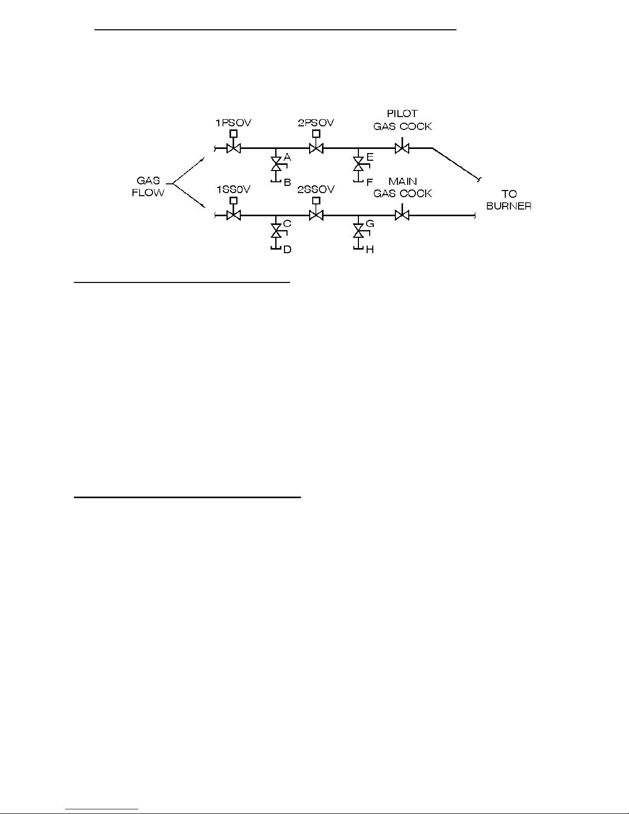
12 APPENDIX D - SAFETY SHUT OFF VALVE LEAK TEST PROCEDURE
FIRST PILOT SHUT OFF VALVE (1PSOV)
1. Make sure all gas cocks ahead of equipment are open to allow gas flow to equipment and turn
off electrical power to the control panel to assure that there is no power to the pilot shut off
solenoid valves so that they are closed (1PSOV & 2PSOV).
2. Make sure the manual test petcock (A) is closed.
3. Remove the leak test tap plug (B) and connect 1/4" tube to the petcock.
4. Close the pilot gas cock located between the pilot shut off solenoid valves and the burner.
5. Immerse the 1/4" tube vertically ½ inch into a jar of water.
6. Slowly open the test petcock (A).
7. Gas will bubble through the water and stop. If bubbles continue, the valve is leaking and must
be replaced. Do not continue to operate burner until valve is replaced.
8. Close the test petcock (A), remove the 1/4" tube and replace the leak test tap plug (B).
FIRST SAFETY SHUT OFF VALVE (1SSOV)
9. Make sure all gas cocks ahead of equipment are open to allow gas flow to equipment and turn
off electrical power to the control panel to assure that there is no power to the safety shut off
solenoid valves so that they are closed (1SSOV & 2SSOV).
10. Make sure the manual test petcock (C) is closed.
11. Remove the leak test tap plug (D) and connect 1/4" tube to the petcock.
12. Close the main gas cock located between the safety shut off solenoid valves and the burner.
13. Immerse the 1/4" tube vertically ½ inch into a jar of water.
14. Slowly open the test petcock (C).
15. Gas will bubble through the water and stop. If bubbles continue, the valve is leaking and must
be replaced. Do not continue to operate burner until valve is replaced.
16. Close the test petcock (C), remove the 1/4" tube and replace the leak test tap plug (D).
W:\ELECTRICAL\INSTRUCT\FURNACE\FURNACE GENERAL INSTRUCTIONS 2011.DOC 34 of 36
01/2014
Page 35

SECOND PILOT SHUT OFF VALVE (2PSOV)
17. Make sure all gas cocks ahead of equipment are open to allow gas flow to equipment and power
is provided to the control panel. Turn on the Exhauster but do not turn HEAT switch to start to
assure that there is no power to the pilot shut off solenoid valves so that they are closed
(1PSOV & 2PSOV).
18. Make sure the manual test petcock (E) is closed.
19. Remove the leak test tap plug (F) and connect 1/4" tube to the petcock.
20. Close the downstream pilot gas cock located between the pilot shut off solenoid valves and
burner.
21. Immerse the 1/4" tube vertically ½ inch into a jar of water.
22. Depress and hold the VALVE TEST button located at the burner junction box to open the first
pilot shut off solenoid valve (1PSOV) and allow gas pressure to the second pilot shut off
solenoid valve (2PSOV).
23. While holding VALVE TEST button in, slowly open the test petcock (E).
24. Gas will bubble through the water and stop. If bubbles continue, the valve is leaking and must
be replaced. Do not continue to operate burner until valve is replaced.
25. Release VALVE TEST button. Close the test petcock (E), remove the 1/4" tube and replace the
leak test tap plug (F).
26. Open the pilot gas cock located between the pilot shut off solenoid valves and the burner.
SECOND SAFETY SHUT OFF VALVE (2SSOV)
27. Turn on the Blower (Gas cocks open and exhauster still running from step 17) and turn the
HEAT switch to “START”. System will purge and ignite pilot causing main safety shut off valve
(1SSOV) and secondary safety shut off valve (2SSOV) to open.
28. Make sure the manual test petcock (G) is closed.
29. Remove the leak test tap plug (H) and connect 1/4" tube to the petcock.
30. Close the main gas cock located between the safety shut off solenoid valves and burner.
31. Immerse the 1/4" tube vertically1/2 inch into a jar of water.
32. Depress and hold VALVE TEST button located at burner junction box to cause secondary safety
shut off solenoid valve (2SSOV) to close. (NOTE: If customer requested vent valve is installed,
vent valve will also close at this point. Check to make sure vent valve closes and that no gas is
passing from vent valve outlet. To do this, the location of the outlet vent pipe must be found
where it exits the building.)
33. While holding VALVE TEST button in, slowly open the test petcock (G).
34. Gas will bubble through the water and stop. If bubbles continue, the valve is leaking and must
be replaced. Turn HEAT switch to “OFF”. Do not continue to operate burner until valve is
replaced.
35. Close the test petcock (G). Release test button. Remove the 1/4" tube and replace the leak test
tap plug (H).
36. Open the main gas cock located between the safety shut off solenoid valves and burner.
W:\ELECTRICAL\INSTRUCT\FURNACE\FURNACE GENERAL INSTRUCTIONS 2011.DOC 35 of 36
01/2014
Page 36

13 APPENDIX E - WARRANTY AND LIMITATIONS OF REMEDIES
Any equipment sold by GRIEVE is warranted for one (1) year after the Purchaser receives the
equipment to be free from defects of material and workmanship. THERE ARE NO WARRANTIES
WHICH EXTEND BEYOND THE DESCRIPTION ON THE FACE HEREOF; WITHOUT LIMITING
THE GENERALITY OF THE FOREGOING, GRIEVE EXPRESSLY DISCLAIMS ALL IMPLIED
WARRANTIES, INCLUDING THE WARRANTIES OF MERCHANTABILITY AND FITNESS FOR A
PARTICULAR PURPOSE. THE PURCHASER=S EXCLUSIVE REMEDY FOR ANY BREACH OF
THIS WARRANTY SHALL BE FOR THE REPAIR OR REPLACEMENT (AT GRIEVE=S OPTION)
OF THE DEFECTIVE EQUIPMENT OR PART.
Parts under warranty are shipped via ground transportation. Express or expedited shipping costs
are the sole responsibility of the customer. In order to obtain repair or replacement under this
warranty, the user must deliver the defective product or part to GRIEVE=s factory on a prepaid basis
promptly after discovery of the defect. GRIEVE=s warranty ceases to be effective if the equipment
is altered or modified, repaired other than by persons authorized by GRIEVE, misused, used by any
person in an unsafe or unreasonable manner or used other than in accordance with AGRIEVE=s@
written instructions. Although GRIEVE makes no additional or extended warranty with respect to
thermostats, recorders, control equipment or other accessories, to the extent such items may also
be warranted by their respective manufacturers, those warranties are passed on to you by GRIEVE
as agent of the respective manufacturer and not as a separate warrantor.
In no event shall GRIEVE be liable for any direct, indirect, special, incidental or consequential
damages hereunder, whether such damages are sought based on breach of warranty, breach of
contract, negligence, strict liability in tort, or any other theory of legal liability.
W:\ELECTRICAL\INSTRUCT\FURNACE\FURNACE GENERAL INSTRUCTIONS 2011.DOC 36 of 36
01/2014
 Loading...