

Grid Tie PV-5000T-U, PV-8000T-U, PV-10000T-U, PV-15000T-U, PV-20000T-U Installation & Operation Manual
Page 1
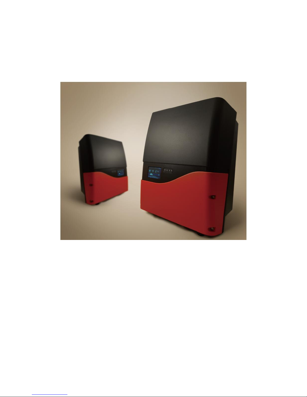
GRID-TIE PV INVERTERS
PV-5000T-U & PV-8000T-U & PV-10000T-U & PV-15000T-U & PV-20000T-U
Installation & Operation Manual
Page 2
1
1. Safety Precautions
Before beginning your journey, please read the following safety instructions
carefully.
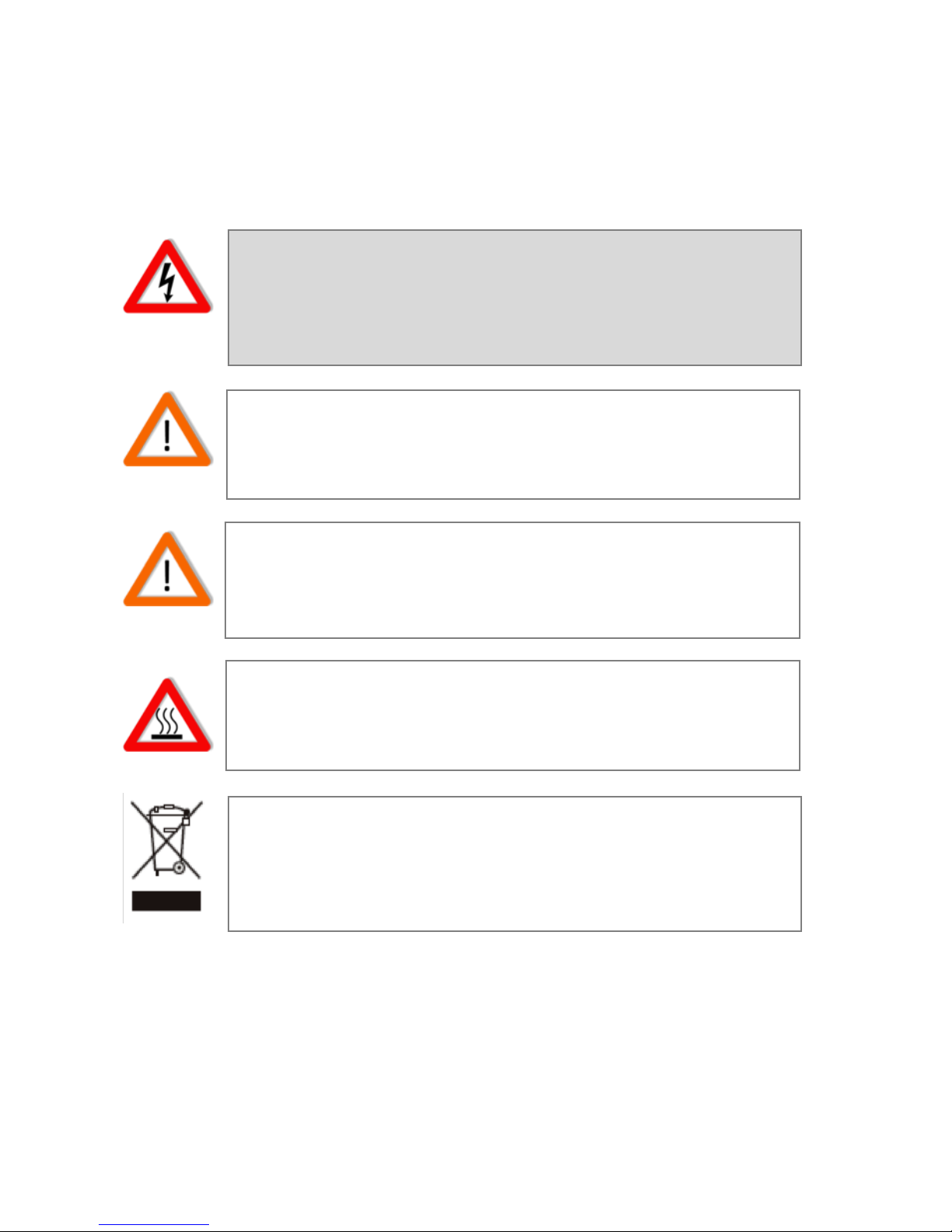
Danger!
High voltage inside inverter can cause Electric shock, even
when inverter is not operating. Wait for at least 30 minutes
before opening the enclosure.
PV Modules ONLY!
Designed for PV and solar power conversion only; do not use
for other DC sources or conversion purposes.
Qualified Personnel ONLY!
Only Qualified technicians shall install or service unit(s) in
accordance with local wiring regulations.
Hot Surface
Metallic parts of enclosure may be hot during operation.
Recycle
Do not throw this electronic device in a trash dumpster when
being disposed of. To minimize pollution of environment,
please consult your local service provider.
Page 3

2
2. Contact Information
PrimeVOLT Co., Ltd.
TEL: +886-2-695-5388
FAX:+886-2-2693-1009
ADD: 11F., No.211, Nanyang St., Xizhi Dist.,
New Taipei City 221, TAIWAN
http://www.primevolt.com
Page 4

3
3. Warranty Information
Warranty or liability will be void if damage caused by, but not limited to the
following:
1. Unauthorized opening of unit
2. Installation faults such as improper environment, wiring and
applications
3. Working conditions beyond specified
4. Improper operation of unit
5. Violation of safety instructions in this manual
6. Damage during transportation
7. Any internal modifications
8. Replacing or installation of unauthorized software
9. Unforeseen calamity or force majeure
Page 5

4
Table of Contents
1. Safety Precautions ........................................................................... 1
Danger! .......................................................................................................................................................................... 1
PV Modules ONLY!............................................................................................................................................... 1
Qualified Personnel ONLY!.......................................................................................................................... 1
Hot Surface................................................................................................................................................................. 1
Recycle ............................................................................................................................................................................ 1
2. Contact Information ....................................................................... 2
3. Warranty Information .................................................................... 3
4. PV System ........................................................................................ 7
5. Product Overview ............................................................................ 8
5.1 PV-5000T-U/PV-8000T-U/PV-10000T-U..........................................................8
5.2 PV-15000T-U…………………………………………………………………….………………………..9
5.3 PV-20000T-U……………………………………………………..………………………..……………10
5.4 Product Labels………………………………………………………..…………………….………….11
6. Installation.... ................................................................................. 12
6.1 Unpacking PV-5000T-U/PV-8000T-U/PV-10000T-U………………….……………...12
6.2 Unpacking PV-15000T-U……………………………………….………………………………...13
6.3.1 Unpacking PV-20000T-U………………………………………….……………………………14
6.3.2 Unpacking PV-20000T-U (E-Display)……………….…………………………………….15
6.4 Assembly Chart (PV-5000T-U/PV-8000T-U/PV-10000T-U/PV-PV15000T-U)….…...16
6.5 Assembly Chart (PV-20000T-U)………………………………………………………………..17
6.6 Choosing Proper Installation Site……………………………………………………………..17
6.7 Mounting Properly…………………………………………………………………………………..19
6.7.1 Orientation ......................................................................................................................................................... 19
6.7.2 Keeping Clearance .......................................................................................................................................... 19
6.8 Mounting Procedure…………………………………………………………………………..…..20
6.8.1 Dimensions of Bracket (PV-5000T-U/PV-8000T-U/PV-10000T-U/PV-PV15000T-U) .. 20
6.8.2 Assembling Bracket ....................................................................................................................................... 20
6.8.3 Mounting Bracket ........................................................................................................................................... 21
6.8.4 Attaching Inverter .......................................................................................................................................... 21
6.8.5 Checking .............................................................................................................................................................. 21
6.8.6 Dimensions of Bracket (PV-20000T-U) ................................................................................................ 22
6.8.7 Mounting Bracket ........................................................................................................................................... 22
6.8.8 Attaching Inverter .......................................................................................................................................... 23
6.8.9 Checking .............................................................................................................................................................. 23
6.9 Wire Connections…………………………………………………………………………………..24
6.9.1 Opening Front Cover ..................................................................................................................................... 24
6.9.2 Overview of Connection Area .................................................................................................................... 24
6.9.2.1 PV-5000U-T/PV-8000T-U/PV-10000T-U ........................................................................................ 24
6.9.2.2 PV-15000T-U/PV-20000T-U .................................................................................................................. 25
6.9.2.3 PV-15000T-U/PV-20000T-U (E-Display) ........................................................................................ 26
Note on AC Circuit Breakers ................................................................................................................................. 26
6.9.3 AC Wiring ............................................................................................................................................................ 27
Note on Wire Selection ............................................................................................................................................ 29
6.9.4 Ripple Control Receiver (RCR) and RS485 Connections ............................................................... 29
6.9.5 RJ45 Connection .............................................................................................................................................. 30
6.9.6 Connecting GFCI Buzzer (Optional) ....................................................................................................... 30
Place the Buzzer Where You Can Hear ............................................................................................................ 30
Page 6

5
6.9.7 Closing the Front Cover ................................................................................................................................ 31
6.9.8 Applicable PV Modules ................................................................................................................................. 31
6.9.9 DC (PV) Wiring ................................................................................................................................................. 31
Danger of Electric Shock! ....................................................................................................................................... 33
Polarity & Voltage Check ........................................................................................................................................ 33
Multiple PV Connections for PV-8000T-U/PV-10000T-U/PV-15000T-U/ PV-20000T-U ........ 33
6.9.10 Unplugging PV ............................................................................................................................................... 33
Be Sure to SWITCH OFF PV ................................................................................................................................... 34
6.10 Ready to Start……………………………………………………………….…..…………………34
6.10.1 Checklist ............................................................................................................................................................ 34
6.10.2 Changing Grid Connection and Operation Parameters ............................................................. 35
6.10.3 Start-up Procedure of Inverter .............................................................................................................. 36
7. Operation………………………………………………………………………………37
7.1 Overview……………………………………………………………………………………………….37
7.1.1 LCD ......................................................................................................................................................................... 37
7.1.2 Icons on LCD ...................................................................................................................................................... 37
7.1.3 Touch Pad ........................................................................................................................................................... 38
7.1.4 Icons on Touch Pad ........................................................................................................................................ 38
7.2 Setting Clock………………………………………………………………………………………….38
Incorrect Clock Settings? ………………………………………………………………………………………………….39
Keeping the Clock Settings ..................................................................................................................................... 39
Self-calibration of Clock .......................................................................................................................................... 40
7.3 Status LED .............................................................................................................................................................. 40
7.4 Frames…………………………………………………………………………...……………………..41
7.4.1 Operation Chart ............................................................................................................................................... 41
7.4.2 Home Screen & Daily Frame ...................................................................................................................... 42
7.4.3 Monthly Frame ................................................................................................................................................. 42
7.4.4 Daily Error Frame .......................................................................................................................................... 43
7.4.5 Operation Frame ............................................................................................................................................. 43
7.4.6 Error Frame ....................................................................................................................................................... 44
Note on “KEEP PV OFF” ........................................................................................................................................... 45
Ground Fault Alarm .................................................................................................................................................. 45
7.5 Network and Internet…………………………………………………………………………….46
7.5.1 Accessing Inverter via LAN (Local Area Network) ......................................................................... 46
7.5.2 Accessing Inverter via Internet ................................................................................................................ 46
7.6 Using USB………………………………………………………………………………………………47
7.6.1 Plugging in USB Stick .................................................................................................................................... 47
7.6.2 Downloading Inverter Data ....................................................................................................................... 47
Data Format ................................................................................................................................................................. 47
Note on Firmware Upgrade .................................................................................................................................. 47
7.6.3 Firmware Upgrade ......................................................................................................................................... 48
7.6.4 Setting PF and 70% Power Limit ............................................................................................................ 48
7.6.5 Capacity of Memory ....................................................................................................................................... 48
Back Up Inverter Data Periodically................................................................................................................... 48
7.7 Browsing Inverter Web Page…………………………………………………………………48
7.7.1 Basics .................................................................................................................................................................... 48
7.7.2 Overview .............................................................................................................................................................. 49
7.7.3 Settings................................................................................................................................................................. 50
Some Items May Not Be Changed ....................................................................................................................... 51
7.7.4 RCR Information ............................................................................................................................................... 51
RCR Cannot Be Set via Web ................................................................................................................................... 52
Page 7

6
8. RS485..………………………………………………………………………………….53
8.1 About RS485……………………………….………………………………………..……………..53
8.2 Connecting RS485……………………….………………………..……………………………..53
8.2.1 RS485 Segments ............................................................................................................................................... 53
8.2.2 RS485 Segments PV-20000T-U ( E-Display )......................................................................................... 54
8.2.3 Wiring Diagram ................................................................................................................................................ 54
8.2.4 Address Setup .................................................................................................................................................... 54
8.2.5 Setting the Terminal Resistor ..................................................................................................................... 55
Attention! ....................................................................................................................................................................... 55
9. Connecting to Ripple Control Receiver (RCR)………………………..56
9.1 Connections with Single Inverter…………………………………………….……...57
9.2 Connections with Multiple Inverters………………………………………..……...57
10. E-Series (Optional)………………………………………….…………………………………58
10.1 LED Panel Only (Solution A) .......................................................................................................................... 58
10.2.1 Stand-by Mode ............................................................................................................................................... 59
10.2.2 Countdown Mode ......................................................................................................................................... 60
10.2.3 Regular Mode ................................................................................................................................................. 60
10.2.4 Error Messages............................................................................................................................................... 62
10.3 LED Panel + LCM Panel (Solution C)…………………………………………………...64
10.3.1 Welcome Mode ............................................................................................................................................ 64
10.3.2 Regular Mode ............................................................................................................................................... 64
10.3.3 Error Mode ....................................................................................................................................................... 66
10.3.4 Last ERROR Information Frame .............................................................................................................. 68
11. Maintenance………….…………………………………………………………….69
11.1 Replacing Fans………….……………………………………………..………………………..70
Be sure to SWITCH off PV and AC ....................................................................................................................... 70
11.1.1 Replacing Internal Fan .............................................................................................................................. 70
11.1.2 Replacing External Fan ............................................................................................................................. 70
12. Troubleshooting…….……….…………………………………………………….71
13. Specifications…………….………………………………………………………….72
13.1 PV-5000T-U/PV-8000T-U/PV-10000T-U ……………………………………………..72
13.2 PV-15000T-U……………………………………………………………………………………….74
13.3 PV-20000T-U……………………………………………………………………………………….76
13.4 PV-20000T-U(E-Display)…..………………………………………………………………….78
14. Addendum……………………..……………………………………………………..80
14.1 Efficiency Charts……..………………………………………………………………………….80
14.1.1 PV-5000T-U ..................................................................................................................................................... 80
14.1.2 PV-8000T-U ..................................................................................................................................................... 80
14.1.3 PV-10000T-U ................................................................................................................................................. 81
14.1.4 PV-15000T-U ................................................................................................................................................. 81
14.1.5 PV-20000T-U .................................................................................................................................................. 82
Page 8
7
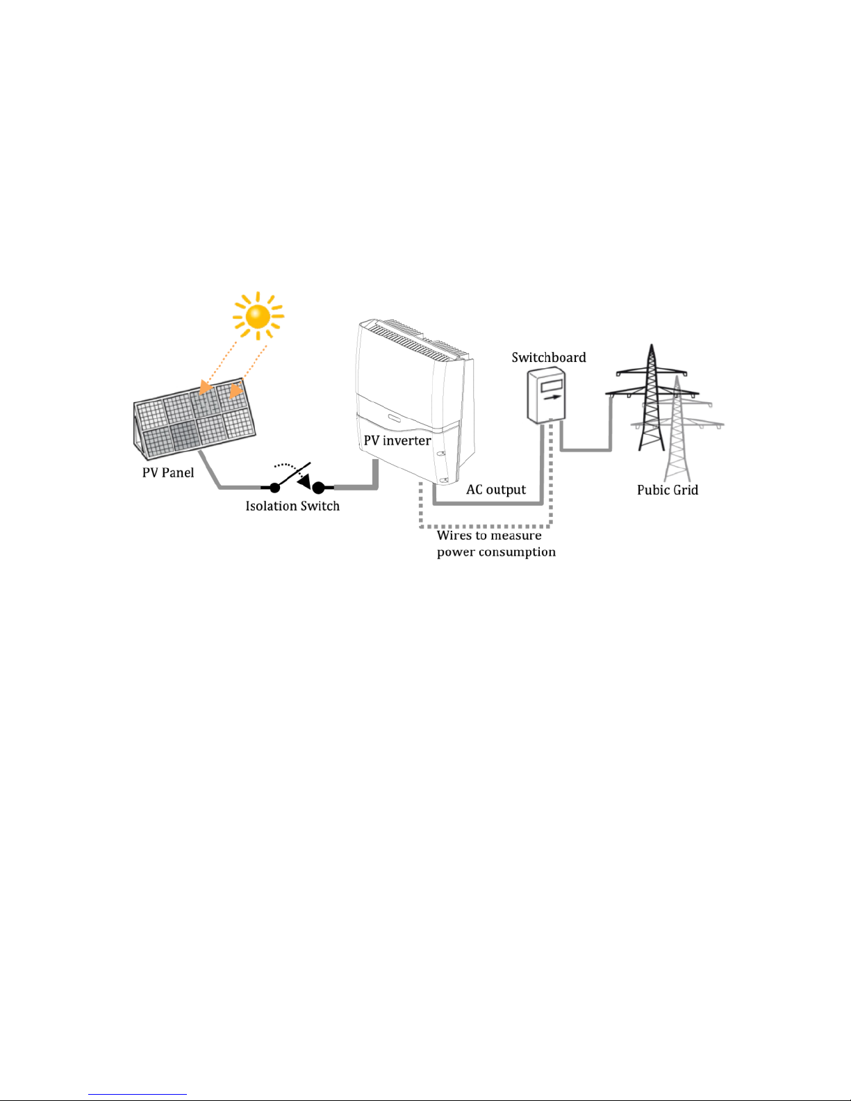
4. PV System
A typical PV system contains:
1. PV Generator: Receive sunlight and generate DC power
2. PV Inverter with DC Switch: Converts DC power by PV panels to AC
output power for public grid
3. Switchboard: Links between PV inverter and public grid
4. Public Grid: Provides utility for homes
Page 9
8
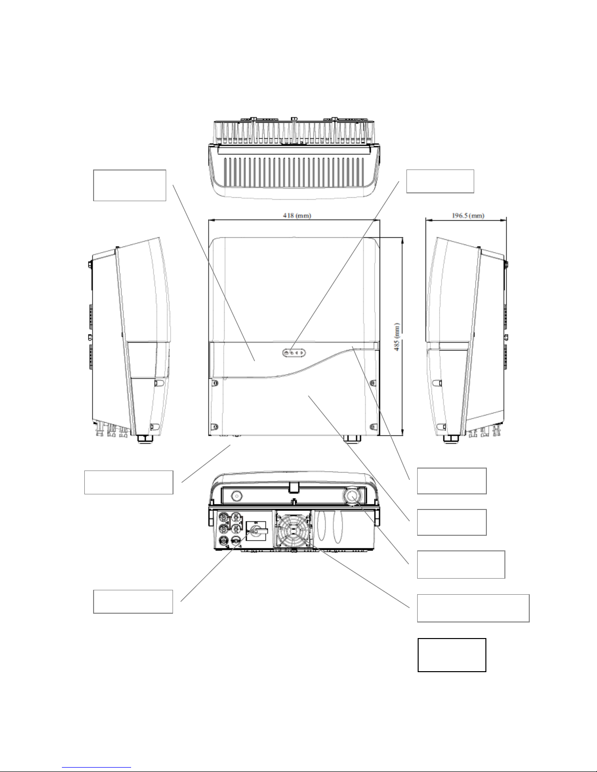
5. Product Overview
5.1 PV-5000T-U/PV-8000T-U/PV-10000T-U
Note: Only 1 DC input for model PV-5000T-U
DC (PV) Input(s)
Display LCD
Touch Pad
Front Cover
AC Cable Gland
Status LED
DC Switch
Unit: mm
External Cooling Fan
Page 10
9
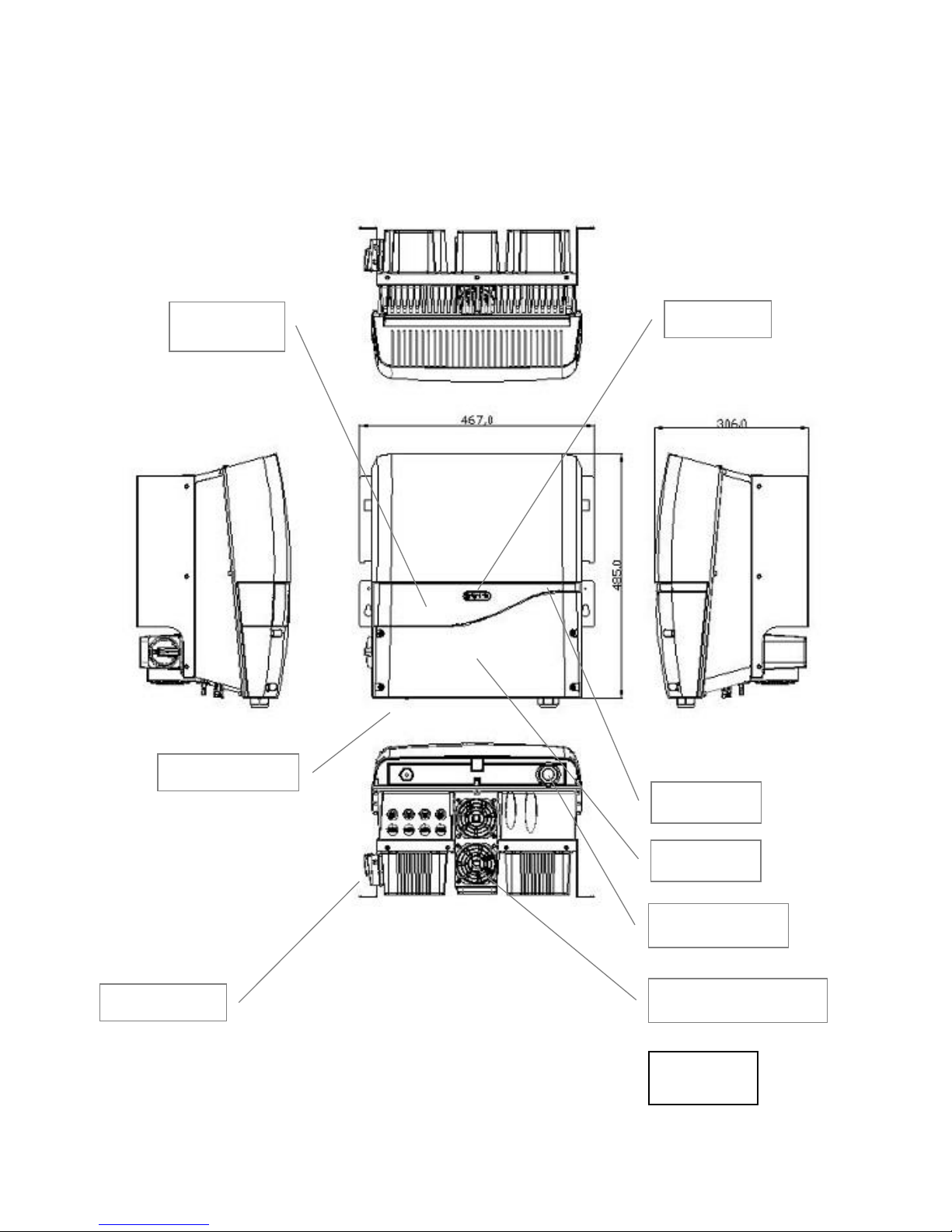
5.2 PV-15000T-U
DC (PV) Inputs
Display LCD
Touch Pad
Front Cover
AC Cable Gland
Status LED
DC Switch
Unit: mm
External Cooling Fan
Page 11
10
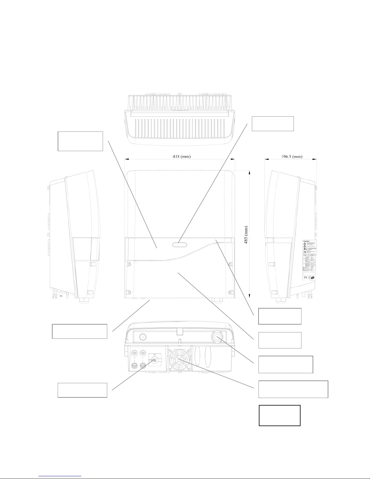
5.3 PV-20000T-U
DC (PV) Inputs
Display LCD
Front Cover
AC Cable Gland
Status LED
DC Switch
Unit: mm
External Cooling Fan
Touch Pad
Page 12
11
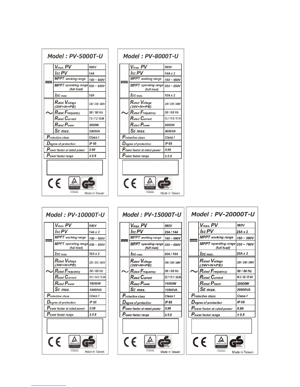
5.4 Product Labels
Page 13
12
6. Installation
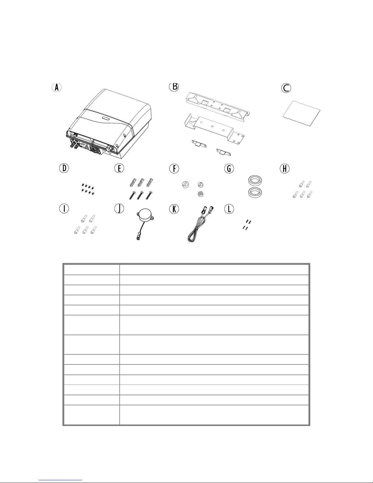
6.1 Unpacking PV-5000T-U/PV-8000T-U/PV-10000T-U
Item
Description
A
Inverter
B
Mounting Bracket Assembly
C
User Manual
D
M4 Flat Screws X 8, used for bracket
E
Plastic Anchor & Screws × 3. Used to fix bracket on
wall
F
Rubber Sealing for Ethernet, RS485, RCR and
buzzer wires. M25 × 1, M20 x 2
G
Clip-on EMI core for Ethernet cable
H
Insulated core end terminals (2.5 mm2) x 5
I
Insulated core end terminals (4.0 mm2) x 5
J
Buzzer for GFCI (Optional)
K
Extending wire for Buzzer (Optional)
L
2 pairs of anchors and screws for fixing buzzer
(Optional)
Page 14

13
6.2 Unpacking PV-15000T-U
Page 15
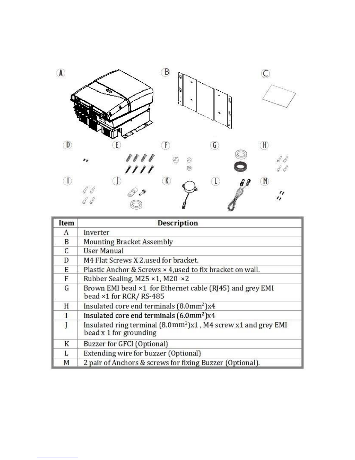
14
6.3.1 Unpacking PV-20000T-U
Page 16
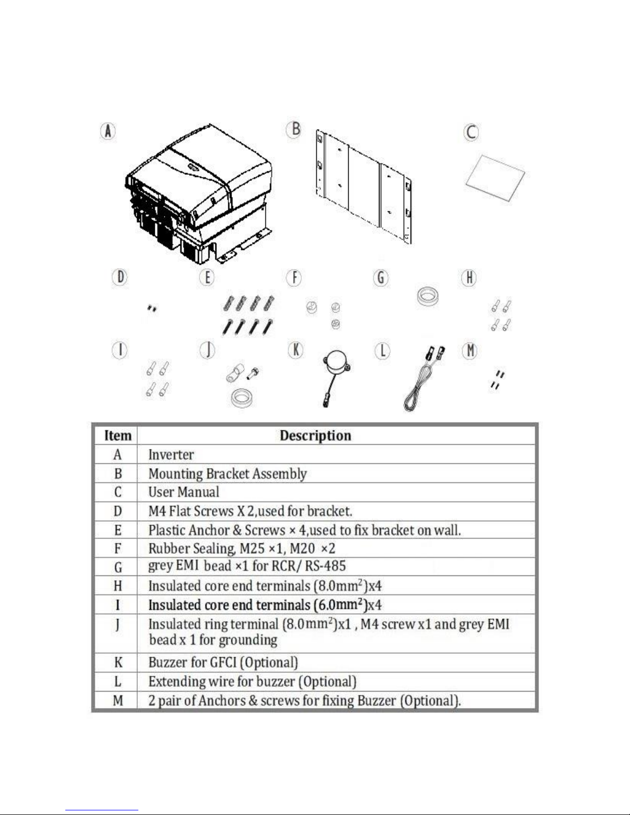
15
6.3.2 Unpacking PV-20000T-U (E-Display)
Page 17
16
6.4 Assembly Chart (PV-5000T-U/PV-8000T-U/PV-10000T-U/PV-PV15000T-U)
Page 18
17
6.5 Assembly Chart (PV-20000T-U)
Page 19
18
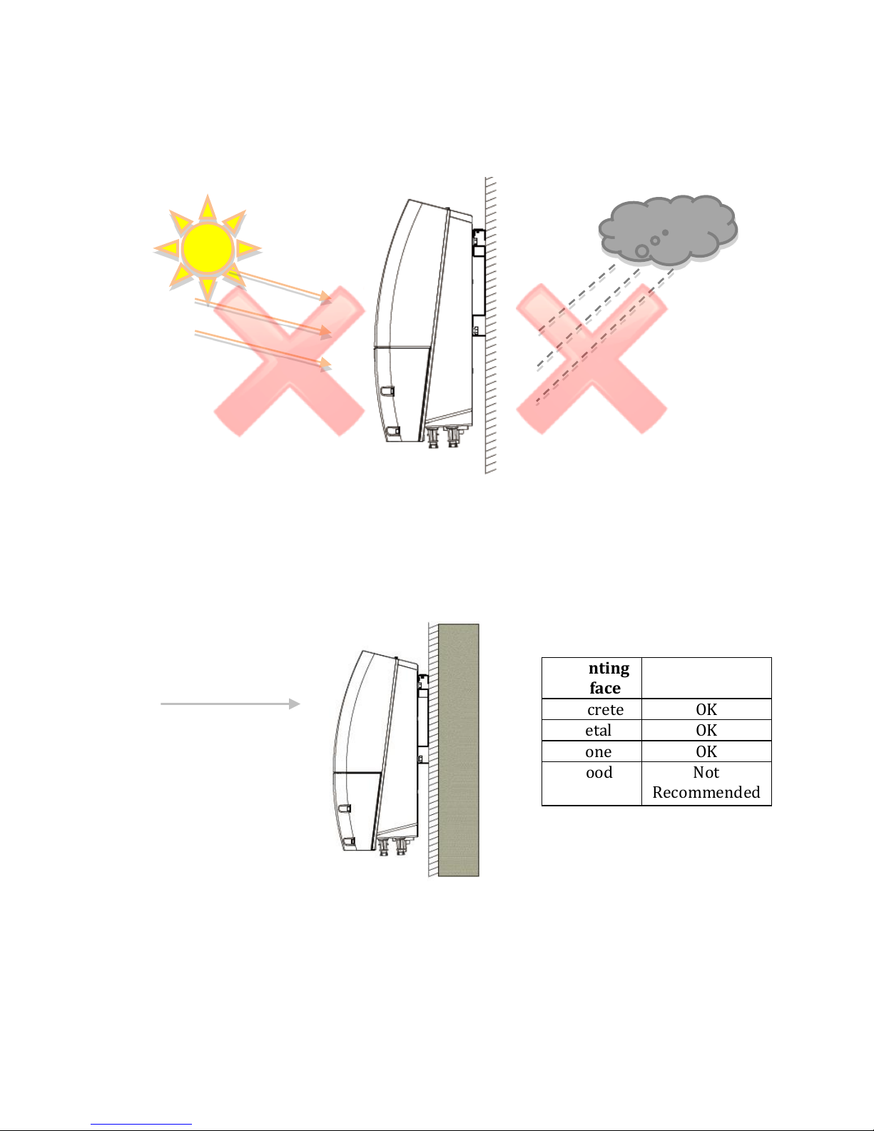
6.6 Choosing Proper Installation Site
Avoid exposing the inverter in direct sunlight or to rain.
Mounting
Surface
Concrete
OK
Metal
OK
Stone
OK
Wood
Not
Recommended
Direct Sunlight
Direct Rain
Visible Level
Page 20

19
6.7 Mounting Properly
6.7.1 Orientation
6.7.2 Keeping Clearance
Mount the inverter vertically; tilt or horizontal mounting shall be avoided.
Page 21
20
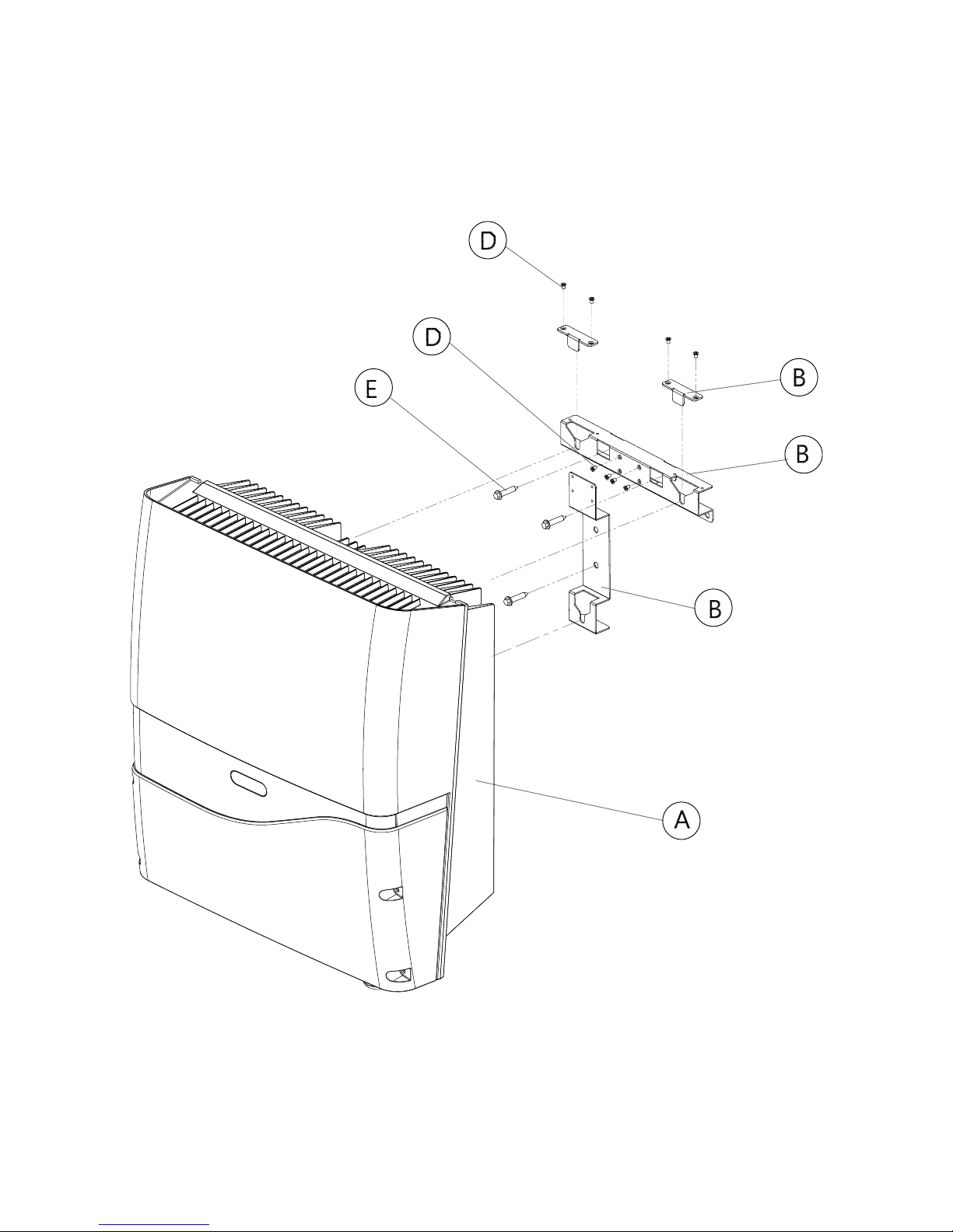
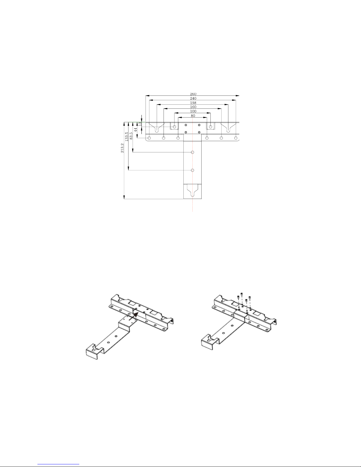
6.8 Mounting Procedure
6.8.1 Dimensions of Bracket (PV-5000T-U/PV-8000T-U/PV-10000T-U/PV-PV15000T-U)
The bracket is used to support inverter on wall. Refer to the recommendations
below to complete mounting.
6.8.2 Assembling Bracket
Before fixing on wall, assemble the bracket as below.
Page 22

21
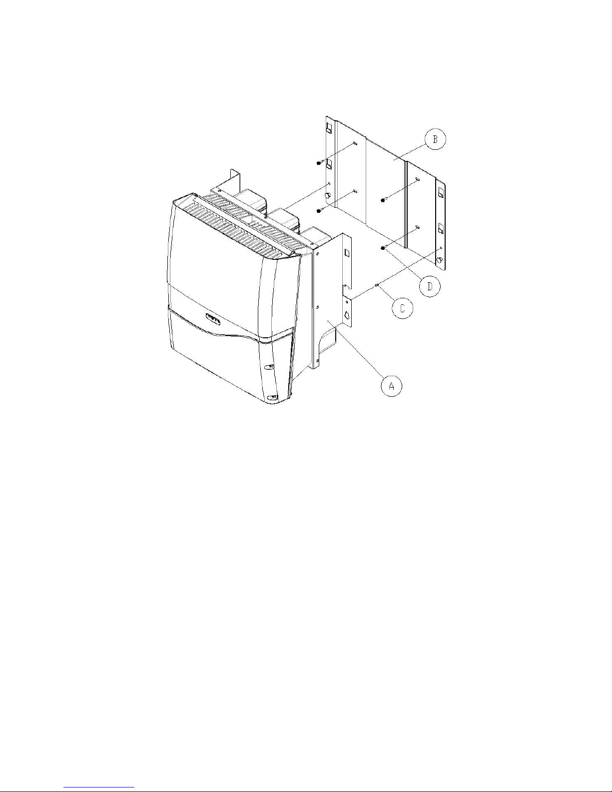
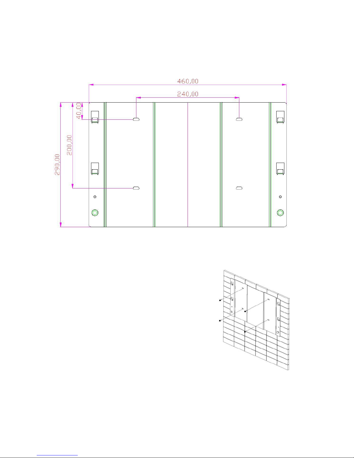
6.8.3 Mounting Bracket
Place the assembled bracket on where
the inverter will be installed. Make proper
drill holes and mount the assembled
bracket with screws from accessory kit.
For safe and firm mounting, make at least
3 drill holes in a triangular manner as
demonstrated on right.
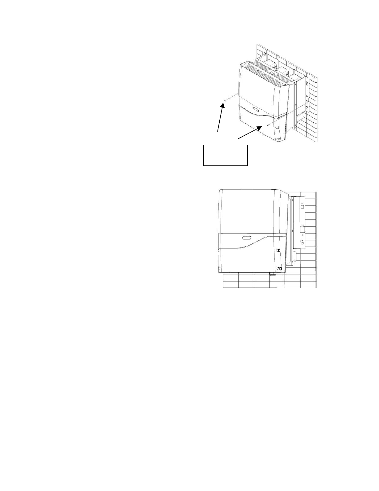
6.8.4 Attaching Inverter
1. Lift inverter slightly higher than
bracket; Make sure all fixing points
on back are at correct positions
2. Attach inverter on bracket
3. Hang inverter on bracket slowly
4. Fix lock caps with screws from
accessory kit
6.8.5 Checking
1. All supporting points are firm
2. Lock caps are tightened with
screws
3. Inverter is well installed and
secured on wall
Page 23
22
6.8.6 Dimensions of Bracket (PV-20000T-U)
The bracket is used to support inverter on wall. Refer to the recommendations
below to complete mounting.
6.8.7 Mounting Bracket (PV-20000T-U)
Place the assembled bracket on where
the inverter will be installed. Make proper
drill holes and mount the assembled
bracket with screws from accessory kit.
For safe and firm mounting, make at least
4 drill holes in a triangular manner as
demonstrated on right.
Page 24
23
6.8.8 Attaching Inverter (PV-20000T-U)
1 Lift inverter slightly higher than
bracket; Make sure all fixing points
on back are at correct positions
2 Attach inverter on bracket
3 Hang inverter on bracket slowly
4 Fix lock caps with screws from
accessory kit
6.8.9 Checking (PV-20000T-U)
1. All supporting points are firm
2. Lock caps are tightened with
screws
3. Inverter is well installed and
secured on wall
Lock Caps
Page 25
24
6.9 Wire Connections
6.9.1 Opening Front Cover
1. Remove the 4 screws on cover as shown
on right
2. Take off the cover gently
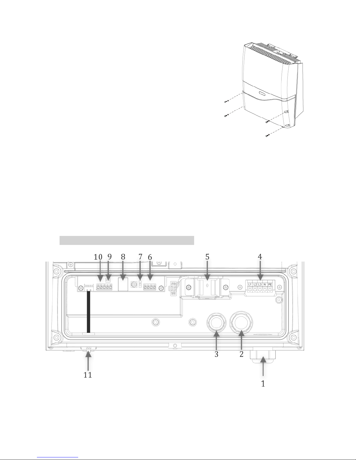
6.9.2 Overview of Connection Area
6.9.2.1 PV-5000U-T/PV-8000T-U/PV-10000T-U
1. Cable Gland- AC cables
2. Cable Glands- Ethernet & RS485
3. Cable Glands- Ripple Control receiver (RCR) & external GFCI buzzer
4. AC terminal block
5. Internal cooling fan (only for PV-8000T-U/PV-10000T-U)
6. RS485 terminal
7. RS485 address selector and associated terminal switch
8. RJ45 socket
9. Socket for external GFCI buzzer (reserved)
10. Ripple control receiver (RCR)
11. USB socket
PV-5000T-U/PV-8000T-U/PV-10000T-U
Page 26
25
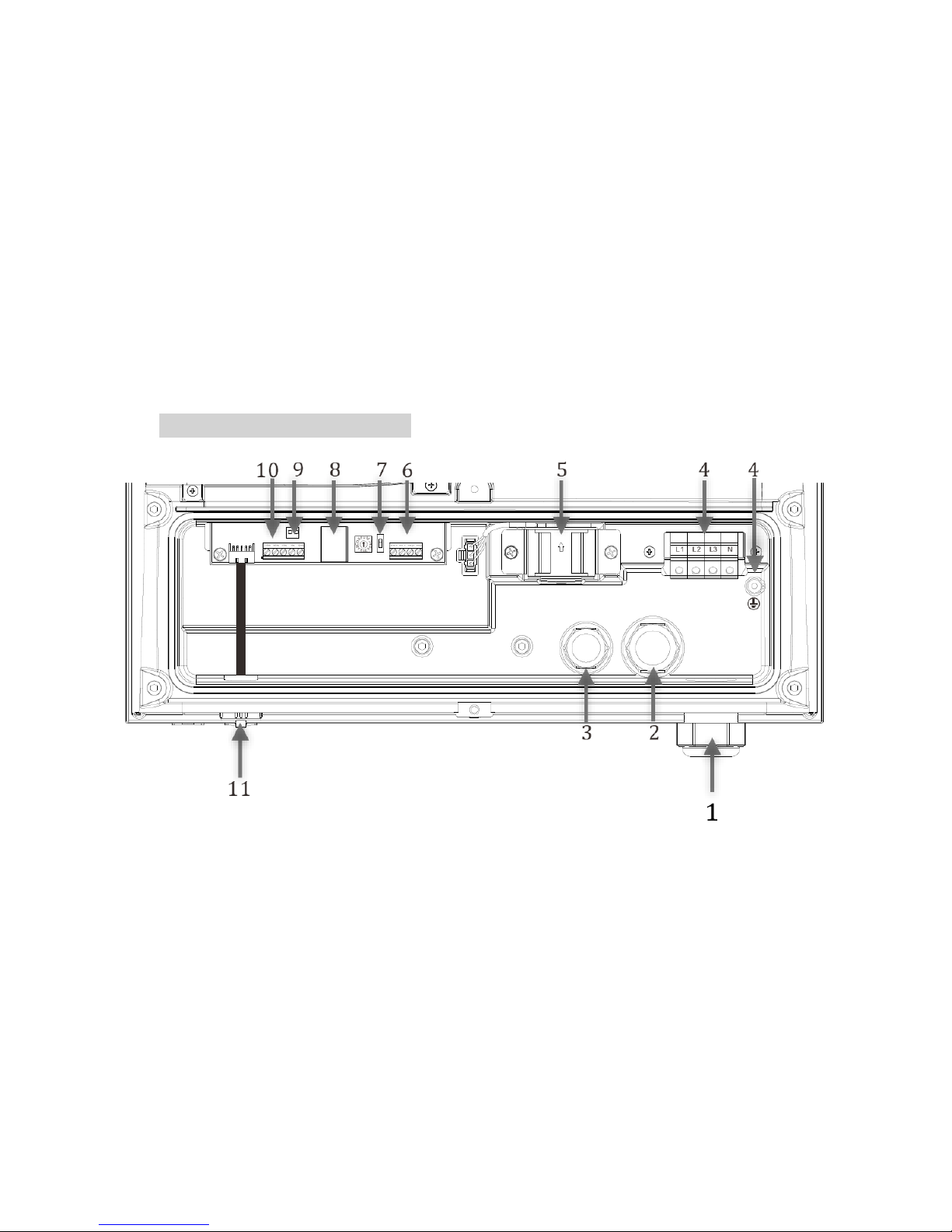
6.9.2.2 PV-15000T-U/PV-20000T-U
1. Cable Gland- AC cables
2. Cable Glands- Ethernet & RS485
3. Cable Glands- Ripple Control receiver (RCR) & external GFCI buzzer
4. AC terminal block (PE or GND is located separately)
5. Internal cooling fan
6. RS485 terminal
7. RS485 address selector and associated terminal switch
8. RJ45 socket
9. Socket for external GFCI buzzer (reserved)
10. Ripple control receiver (RCR)
11. USB socket
PV-15000T-U/PV-20000T-U
Page 27

26
6.9.2.3 PV-15000T-U/PV-20000T-U (E-Display)
1. Cable Gland- AC cables
2. Cable Glands- RS485
3. Cable Glands- external GFCI buzzer
4. AC terminal block (PE or GND is located separately)
5. Internal cooling fan
6. RS485 terminal
7. RS485 address selector and associated terminal switch
8. Socket for external GFCI buzzer (reserved)
PV-15000T-U/PV-20000T-U (E-Display)
Note on AC Circuit Breakers
For safety reasons, place an independent circuit breaker
between inverter and grid BEFORE all connections. Make
sure inverter will be safely disconnected from the grid in all
circumstances. It is recommended to use certified 10A/250V
(PV-5000T-U) or 20A/250V(PV-8000T-U & PV-10000T-U) or
30A/250V (PV-15000T-U) or 35A/250V (PV-15000T-U &
PV-20000T-U) circuit breakers.
4 5 4
8
1 2 3
7 7 6
Page 28

27
6.9.3 AC Wiring
1. Prepare cables as recommended below
Cross
Section
(mm2)
Maximum Length for 1% Loss (M)
PV-5000T-U
PV-8000T-U
PV-10000T-U
PV-15000T-U
PV-20000T-U
2.5
17
11
9
N/A
N/A
4
28
18
14
N/A
N/A
6
42
26
21
14
N/A
10
N/A
N/A
N/A
23
17
14
N/A
N/A
N/A
N/A
24
Table above is based on single-core copper wires with maximum
temperature rise of 60°C. The following factors should be taken into
account when it comes to actual wiring:
Ambient temperature
Wiring nearby
Cooling
Please follow local standards if figures above are different from.
1. Remove strip insulation ~ 9 or 10 mm
2
2. Remove sealing plug, twist off the AC cable gland
3. Insert AC cable through M32 rubber sealing and hole
4. Fix L1 (Line 1), L2, L3, N (Neutral) and PE ( ) on terminal block
5. Tighten cable gland to secure cables in position
PV-5000T-U/PV-8000T-U/PV-10000-U PV-15000T-U
PV-20000T-U
Page 29

28
PV-5000T-U/PV-8000T-U/PV-10000T-U
PV-15000T-U/PV-20000T-U
The EMI core in figure above comes from item J in Ch.6.2 Unpacking PV-
15000T-U & Ch.6.3.1 Unpacking PV-20000T-U on P.13, P.14 & P.15. Please
make sure the GND cable (green) is wound thru a grey EMI core with 3
turns for noise immunity, as illustrated above.
Page 30

29
6.9.4 Ripple Control Receiver (RCR) and RS485 Connections
1. Remove sealing plug and twist off the cable gland (M25)
2. Insert wires from rear of guidance and holes of rubber sealing (M25)
3. Refer to Ch.8 on P.47 for proper RS485 connections
4. Refer to Ch.9 on P.49 for proper RCR connections
5. Connect RCR and RS485 wires as shown below
6. Make sure RCR and RS485 wires are both wound through a grey EMI
core (from accessary kit) with 4 turns each, as for noise immunity
7. Tighten cable gland to secure cables firmly in position
PV-5000T-U/PV-8000T-U/PV-10000T-U
PV-15000T-U/PV-20000T-U
PV-15000T-U/PV-20000T-U (E-Display)
Note on Wire Selection
To safely secure cable on terminal block, please use solid
wires. If stranded wires are used, apply core end terminals
supplied in accessories.
Page 31

30
6.9.5 RJ45 Connection
RJ45 is specifically employed here for LAN/WLAN via which inverter web page
can be easily accessed. Refer to figures below and on P.25 for RJ45 wiring. Make
sure that RJ45 cable is wound through the brown EMI core (from accessary kit)
with 4 turns each, as for noise immunity
6.9.6 Connecting GFCI Buzzer (Optional)
Buzzer is used to alert user when ground fault current interrupter (GFCI) is
active. It’s also known as residual current monitoring unit (RCMU).
1. Insert extension cord through the M20 cable gland and connect to
designated socket on inverter, as illustrated below and on P.25
2. Attach and fix the buzzer on an indoor surface such as a wall
3. Connect buzzer with extension cord
4. If the length of cord is not enough, please trim and extend with some
similar cord to desired length
PV-5000T-U/PV-8000T-U/PV-10000T-U
PV-15000T-U/PV-20000T-U
Place the Buzzer Where You Can Hear
The buzzer will notice you in case of ground current fault.
Place it near you. Do not put in a cabinet or place far away.
Extension Cord for Buzzer
RJ45 Cable for Internet
Extension Cord for Buzzer
RJ45 Cable for Internet
Page 32

31
PV-15000T-U/PV-20000T-U (E-Display)
6.9.7 Closing the Front Cover
After connecting all wires, please
1. Inspect all the connections again
2. Close front cover and tighten 4 screws gently
3. Check for any openings in between front cover and inverter
6.9.8 Applicable PV Modules
Only non-grounding PV panel is applicable, user is suggested to consult with a
system installer for PV panel type selection.
6.9.9 DC (PV) Wiring
1. DC Input Ratings
Model
Rating
PV-5000T-U
PV-8000T-U
PV-10000T-U
PV-15000T-U
PV-20000T-U
Recommended
Max. DC Power (W)
5500
8800
11000
16500
22000
Max. DC (V)
980
980
980
980
980
Max. Current (A)
10
10/String
20 in Total
10/String
20 in Total
20 for
String 1
(Paralleled)
10 for
String 2
30 in Total
20/String
40 in Total
String(s)
1 2 2
2 (3 Inputs)
2 (4 Inputs)
Warning
Require PV modules that have IEC 61730 class A rating.
RS485 Cable for Internet
Page 33

32
2. Use either connector
a. Wieland PST40i1C (Preferred)
b. Multi-Contact MC4
3. Connect to PV
After all the associated cables and connectors have been prepared,
1. Remove sealing plugs as depicted on right
2. Plug in PV cables gently as depicted below
PV-8000T-U & PV-10000T-U PV-5000T-U
PV-15000T-U PV-20000T-U
PV1 (+) PV1 (-)
PV1 (+)
PV2 (+) PV2 (-)
PV1 (-)
PV1 (+) PV1 (-)
PV1 (+) PV1 (-)
Paralleled DC Feeds
PV1 (+)
PV2 (+)
PV1 (-)
PV2 (-)
PV2 (+) PV2 (-)
Page 34

33
6.9.10 Unplugging PV
In case you need to disconnect the PV,
follow the steps below.
a. SWITCH OFF PV!
b. Use preferred Wieland
assembling/disconnecting
mounting tool PST (Art. No.
05.502.1753.0)
c. Push interlock to release plugs
d. Pull off plugs
Danger of Electric Shock!
While working on DC wiring, make sure DC is completely
turned off.
Polarity & Voltage Check
Before plugging in, make sure all polarities and voltages are
correct. Incorrect connections could cause malfunction.
Multiple PV Connections for PV-8000T-U/PV-10000T-U/PV-15000T-U/
PV-20000T-U
Either two paralleled DC feeds from one common PV string
or two independent DC strings can be set up for PV-8000T-U
& PV-10000T-U. Two paralleled DC feeds from one common
PV string and a single DC feed from another independent PV
string MUST BE set up for PV-15000T-U in accordance with
hardware specifications. The inverter will then adjust to
optimal performance accordingly by itself.
Keep the Sealing Plugs
Please keep those plugs in a safe place. You may need to use
them again in case removal of DC connectors is needed.
Page 35

34
6.10 Ready to Start
6.10.1 Checklist
Before starting the inverter, please check the following items:
Item
Check Points
Checked?
Mounting
Inverter is firmly mounted on
bracket(s)
The 2 lock caps are secured
Locks are closed
AC
All cables are firmly fixed on
terminal block
Polarities are matched
Protective Ground is available
Cable gland is tightened firmly
RS485
RJ45
Ripple Control
Receiver
All terminals are secured
Polarities are matched
Wires are tightened by cable
gland
If not used, sealing plugs are in
position
Item
Check Points
Checked?
Front Cover
Front cover is firmly attached
All screws are secured
DC
All plugs are firmly connected
Polarities are matched
Strings are not mixed wired (for
multiple MPPT models)
Be Sure to SWITCH OFF PV
Direct pull-off of DC plugs can lead to sparks. Be sure to
switch off PV beforehand.
Page 36

35
6.10.2 Changing Grid Connection and Operation Parameters
If you need to change grid connection settings and/or operation parameters
including voltages, frequency range, power factor and power limitation, please
contact your local authorized service provider for an “USB key” to do so.
After modifying, for the sake of verifying changed settings, please refer to
Ch.7.4.5 Operation Frame on P.43.
Page 37

36
6.10.3 Start-up Procedure of Inverter
Start
Checklist &
Settings OK?
Switch on AC
Wait for 40 Seconds
LCD & Touch
Pad On?
Switch AC Off
Check AC
Switch PV (DC) on
Wait for 2 Mins
Producing
Power?
Switch PV (DC) Off
Check PV
Ethernet
OK?
Check Ethernet
Connection
END
Yes
No
Yes
Yes
Yes
No
No
No
Page 38

37
7. Operation
7.1 Overview
7.1.1 LCD
7.1.2 Icons on LCD
Icon
Description
Note
USB. Appears when USB port in use; flashing
while accessing data.
RS485. Appears when there is data transfer
via RS485.
Wi-Fi. Appears when Wi-Fi dongle is
connected. Refer to manual of Wi-Fi dongle.
Ethernet. Appears when Ethernet is
connected.
Sun. Appears during daytime.
PV module. Appears when PV connected.
Utility. Appears when electrical grid is
present.
Power feeding. Appears while inverter is
feeding power to electrical grid.
Active Interfaces
Time & Date
Sun & PV panel
Graph & Text Area
AC Power
Power Flow
Energy
Hours or Days
Page 39

38
7.1.3 Touch Pad
Touch pad is used to change frame displayed on LCD screen.
7.1.4 Icons on Touch Pad
Icon
Description
Note
Home. Returns to Home Screen.
Toggle. Toggles between frames for
information.
Backward. Switches to previous daily
(monthly) frame.
Forward. Switches to next daily (monthly)
frame.
7.2 Setting Clock
During the first installation of inverter where the internal clock has not been set,
the system will automatically prompt user to set time and date.
Page 40

39
The flashing characters are the fields to be set. Use touch pad for all entries.
When completed, tap to finish and confirm your new settings.
The following table depicts functions of touch pad keys.
Icon
Function
Note
Confirms settings.
Switches views among Year, Month, Day, Hour
and Minute.
Decreases entry value.
Increases entry value.
Incorrect Clock Settings?
In case of incorrect settings, switch to “Information frame” to
make adjustments afterwards.
Keeping the Clock Settings
In cases where the AC has been disconnected for more than
3.5 hours, the internal clock of inverter will roll back to
factory default settings.
Page 41

40
7.3 Status LED
This LED indicates operation status of inverter by color. In normal operation, it
appears green; in circumstances where inverter goes faulty, it appears red.
Status
Indication
Inverter is not connected to AC.
Solid Green: Inverter is standing by/operating (day).
Flashing Green: Inverter is standing by (evening/night).
Solid Red: Inverter is having a fault.
Self-calibration of Clock
If the inverter is connected to the Internet, the clock will
synchronize with a local time server automatically. To do this,
you will need to set the time zone and time server via internal
web server. Please refer to later sections for details.
AC Power
Peak Power of
the Day
Hours
Time & Date
Daily Yield
Graph
Daily Yield
Page 42

41
7.4 Frames
7.4.1 Operation Chart
Note:
1. Tapping will go back to Home (Daily) Frame.
2. Daily Error Frame will not pop up if there have been no errors occurred
during the day.
3. LAN IP and/or Wi-Fi IP will not show on screen if no Ethernet and/or
Wi-Fi connected.
Page 43

42
7.4.2 Home Screen & Daily Frame
The Home Screen (Daily Frame) shows the operation data of a day. The user can
switch to different daily data by tapping FORWARD or BACKWORD. The date on
the upper right side will change accordingly as well.
7.4.3 Monthly Frame
The monthly Frame shows operation data of a month. The user can view data of
a different month by tapping FORWARD or BACKWORD. The month (shown on
upper-right side) will change accordingly.
AC Power
Peak Power of
the Day
Hours
Time & Date
Daily Yield
Graph
Daily Yield
Day
Monthly
Yield
AC Power
Peak Power of
the Month
Month Display
Monthly
Yield Graph
Page 44

43
7.4.4 Daily Error Frame
This frame exists when there have been operation errors during the day.
7.4.5 Operation Frame
This frame shows operational information of inverter. There are five sub-frames
as described here.
1. E-Total & H-Total: E-Total (total accumulated energy) in kWh and H-
Total (total operating time of inverter) in hours
2. LAN and Wi-Fi IP addresses: IP address information of inverter
3. Clock: To set clock, refer to Ch.7.2 Setting Clock on P.38
4. Language: Language displayed on LCD screen
5. Parameters: Grid safety regulation (VDE0126-1-1/A1, VDE-AR-N 4105, or
EN50438), 70% power limit (ON/OFF), and power factor PF (-0.8 ~ +0.8)
6. System Info: F/W version currently installed on inverter
7. Idc & Pdc: The total instantaneous input DC current (unit: A) and total
instantaneous input DC power (unit: kW) from your solar panel(s).
8. Power Limit: The restraint in terms of percentage of rated AC output
power of inverter currently posted by Ripple Control Receiver (RCR).
Error Count
Error Type
Page 45

44
9. Modbus Address: Designated address of inverter for all communication
purposes in the monitoring network.
10. AC Nominal Frequency: GF: 59.5 ~ 60.3Hz; AC Voltage Range: GF: 198.0
~ 248.0V.
7.4.6 Error Frame
An error implicates abnormal activity of the solar system. The frame pops up
automatically after detection of an error. The second text line indicates error
type. Error types are defined in the table below.
Error
Implication
AC VOLT HIGH
Grid (AC) voltage is higher than preset
AC VOLT LOW
Grid (AC) voltage is lower than preset
AC FREQ HIGH
Grid frequency is higher than preset
AC FREQ LOW
Grid frequency is lower than preset
PV VOLT HIGH
PV voltage is higher than allowed
PV ISUL LOW
The insulation resistance between either PV (+) or
PV (-) to earth is lower than 2.0 MΩ
GFCI HIGH
Ground Fault Current is higher than specified
Page 46

45
KEEP PV OFF
Internal capacitor(s) short
User must switch off PV immediately
C1
High DC current detected
C2
Relay failed
Error
Implication
C3
DC current sensor failed
C4
Internal temperature of inverter high
C5
GFCI detection failed
C6
Currently not used by system
C7
Anti-islanding (or AFD) failed
FAN FAILS
Internal or external cooling fan failed to work
Note on “KEEP PV OFF”
If this message shows up on screen, please turn off the DC
switch of PV immediately. DO NOT turn on again for any
reason. Call for service immediately.
Ground Fault Alarm
In addition to showing “GFCI HIGH“ on display, inverter will
activate audiable alarm of the optional buzzer and show
message on web page while using a computer to monitor.
Page 47

46
7.5 Network and Internet
7.5.1 Accessing Inverter via LAN (Local Area Network)
The illustration above is a typical LAN connection. The inverter and devices are
connected to a router by Ethernet cable or Wi-Fi. Computers and other devices
in the LAN can access inverter’s data if its IP address is known.
The router, acting as a DHCP server, usually assigns an IP to the inverter
automatically. You can also manually assign an IP to the inverter with the router
as well. Use touch pad to go to “Operation Frame” for IP confirmation.
7.5.2 Accessing Inverter via Internet
The illustration above demonstrates how to access the inverter via Internet.
Similar to LAN, the inverter can be accessed by web browser. However, there is
usually a firewall that would block direct access of the LAN from the Internet. In
order to overcome this, you will need to set up NAT (Network Address
Translation) or Port Forwarding of the router. For detailed information, please
refer to the manual provided by your router supplier.
Router
Router/Modem
Computer via Internet
Computer via LAN
Inverter
Inverter
Page 48

47
7.6 Using USB
7.6.1 Plugging in USB Stick
To acquire inverter data, you can plug in a pre-formatted USB stick into the USB
interface beneath inverter. The stick must be FAT or FAT32 formatted.
Remove the cap and plug in a USB stick. If
inverter recognizes the device, the USB
icon on LCD screen will light up.
7.6.2 Downloading Inverter Data
After plugging in the USB, all data
stored in the inverter will be
downloaded to the stick
automatically. During the download,
USB icon will be blinking.
After downloading, while USB icon stays solid, you can
then safely unplug the stick. The inverter data has
been saved in the USB stick.
Data Format
There will be two data files downloaded. One is for SQLite;
the other is a CSV (Common Separation Value).
Note on Firmware Upgrade
If the USB stick contains an update of firmware, the inverter
will not download data into USB stick but perform firmware
upgrade instead.
USB icon blinks
while data is
being accessed
Page 49

48
7.6.3 Firmware Upgrade
The inverter can be upgraded to the latest firmware version via USB or Internet.
To do this, you will need to have either the firmware update in a USB stick or
the inverter connected to the Internet. Please consult your local service
provider for more details; to do upgrade via Internet; please refer to “Settings”
on page 50 to enable AUTO FW Update functionality.
7.6.4 Setting PF and 70% Power Limit
These parameters can only be done by an authorized agent. Please contact your
local service provider if assistance is needed.
7.6.5 Capacity of Memory
The internal memory of inverter can store up to 3-year length of data. Data
older than 3 year will be overwritten automatically.
7.7 Browsing Inverter Web Page
7.7.1 Basics
Inverter has a built-in and multi-functional web page that user can access via
LAN/WLAN. The recommended web browsers are Internet Explorer, Firefox
and Safari. Follow the steps below to explore the inverter web page.
1. Make sure you have successfully connected inverter to a LAN by either
Ethernet or Wi-Fi.
2. Tap touch pad to switch to “Operation Frame” to read off the inverter’s
IP address.
3. Open a web browser on your desktop/laptop, key in the IP address you
have read previously at the address bar (Refer to figure below. The
example IP address here is 192.168.10.122).
4. Daily graphs will load soon after.
Back Up Inverter Data Periodically
Once the data stored in logger has been deleted, it cannot be
retrieved. It is highly recommended to back up your inverter
data periodically if you wish to retain all recordings.
Page 50

49
7.7.2 Overview
1. Display Tabs: There are 4 selections available.
a. Day: Yield graphs of the day
b. Month: Bar Graphs of a month. When pointing cursor to a
specific day, the corresponding yield of that day will highlight
automatically. See picture below for illustration
IP address
Display Tabs
Daily Graphs
Information Board
Inverter Status
Forward/Backward
Tabs
Page 51

50
c. Logs: Event records of inverter. Events include activities and
errors of inverter. See picture below for demonstration
d. Settings: Information and set-up of inverter
2. Inverter Status: Showing current operation status. During the night
and/or when inverter is not working, the area is black. When an error
or failure happens, a message will pop up.
3. Information Board: Displays power generation and relevant system
parameters. During the night, while inverter is not working, the
“system” data will not be viewable.
4. Forward/Backward Tabs: Move current display forward or backward.
7.7.3 Settings
When in Settings, you will see the table below.
Inverter Info.
PV-5000T-U
Date & Time
Oct/1/2013 11:02:00
Voltage Range
194.0 ~ 264.0 V
Frequency Range
47.50 ~ 51.50 Hz
Grid Regulation
VDE-AR-N 4105
PF
1.00
70% Limit
No
RCR Info.
(Show)
IP Address
192.168.1.121
Wi-Fi
(Edit)
Auto FW Update
ON
Language
English
Feed-in Rate
$0.32
Administration
Admin
For any item you wish to change, move the cursor and click on it. You will be
prompted to enter user name and password before proceeding.
1. Inverter Info. : Name, serial number and
F/W version.
2. Time & Date: Clock of inverter. You can set
the time zone and synchronize with time
server automatically.
Page 52

51
3. Voltage Range: Operation voltage range of inverter.
4. Frequency Range: Frequency range of inverter operation.
5. Grid Regulation: The safety regulation the inverter is currently
complying with.
6. PF: Power factor. Ranging from -0.8 ~ +0.8.
7. 70% Limit: On or Off. Limits AC output power of inverter to 70% of the
original rating.
8. RCR Info: Settings of the Ripple Control Receiver. Refer to “RCR Setting
Information” for details.
9. IP address: The assigned IP address of inverter.
10. Wi-Fi: Settings of Wi-Fi connection, including
a. Wi-Fi SSID.
b. WI-FI Password: The key or
password of your WLAN.
11. Auto FW Update: Yes or No. Select “Yes” will enable automatic F/W
update. Inverter will check latest F/W, download and update
automatically. If “No” is selected, inverter will not check for firmware
updates since.
12. Language: Language selection.
13. Feed-in Rate: The feed-in rate. There are graphs displaying your
earnings in accordance to the rates you entered.
14. Administration: User name and password. The default name is “admin”;
the default password is “admin”.
7.7.4 RCR Information
By clicking on “Show” on the right of “RCR Info,” the current settings of RCR will
show up like the table in next page.
Some Items May Not Be Changed
Items 3 ~ 8 may not be modified without authorization.
Please consult your local authorized service provider.
Page 53

52
K1
K2
K3
K4
Active
Power
Signal Length
2 Sec
100%
Fallback Active
Yes
0%
Fallback Time
10 Min
30%
Fallback Power
100%
75%
60%
70%
10%
50%
100%
20%
100%
0%
60%
70%
20%
90%
1. K1 ~ K4: The relays on RCR.
2. Active: When selected, relays K1 ~ K4 will be active.
3. Power: The corresponding limit on AC output power of inverter.
4. Signal Length: The minimum time required to activate a power limit.
5. Fallback: A fallback is an operation state which the inverter can enter if
relays K1~K4 is not active in the table.
6. Fallback Active: When selected, fallback will take place.
7. Fallback Time: The time required if the input status is not valid.
8. Fallback Power: The power limit for fallback.
RCR Cannot Be Set via Web
To change RCR settings, you may need request a setting tool
from your inverter supplier. Users cannot do this via web.
Page 54

53
8. RS485
8.1 About RS485
A typical RS485 connection is as below.
Some Noteworthy Points:
1. Wires between devices and computer shall be twisted.
2. Maximum allowable wire length is 1000 meters.
3. The terminal-end device should have a terminal resistor.
4. Due to multiple connections, each individual device should be
assigned an IP address as to send/receive.
8.2 Connecting RS485
8.2.1 RS485 Segments
RS485 terminal
Connecting to device or computer
with RS485 interface
Terminal Resistor Switch
T/R 1+
T/R 1-
T/R 2+
T/R 2-
Address Switch
Page 55

54
8.2.2 RS485 Segments PV-20000T-U (E-Display)
8.2.3 Wiring Diagram
1. Connect T/R+ and T/R- of RS485 converter to the T/R1+ and T/R1- of
an inverter respectively.
2. Between two inverters, match T/R2+ and T/R2- of this inverter to
T/R1+ and T/R1- of the next inverter.
3. Set terminal resistor switch “ON” of the terminal-end inverter (last
inverter of the row) only. The others’ should be set as “OFF.”
8.2.4 Address Setup
To do this setting, use the address rotary switch shown on right. For a single
inverter, set the position to “1”; for multiple inverters, please assign them
different positions with no duplications. Since only 15 positions (1~F) are
available, the maximum number of inverters that can be grouped at a time in a
Address Switch
Terminal Resistor Switch
RS485 terminal
T/R 1+
T/R 1-
T/R 2+
T/R 2-
Page 56

55
RS485 bus is 15. Position “0” is reserved for broadcast purposes when multiple
inverters are employed. Please do not use in all circumstances.
8.2.5 Setting the Terminal Resistor
As shown on right, “ON” indicates a resistor is added.
ONLY the terminal-end inverter (last inverter of the row)
should have this switch set to “ON”. Switches of the other
inverters should be set as “OFF.”
Attention!
Incorrect settings could cause communication failure.
ON
OFF
Page 57

56
9. Connecting to Ripple Control Receiver (RCR)
RCR receives control signals from your power company. PV series inverters can
be connected to RCR directly. Inverters will be able to receive command from
RCR and adjust their AC output powers to the corresponding level. A typical
RCR installation is illustrated below.
Page 58

57
9.1 Connections with Single Inverter
When connecting a single inverter only, refer to the figures below.
9.2 Connections with Multiple Inverters
To Other Inverters
Page 59

58
10. E-Series (Optional)
E-Series stands for Economic Series. It offers three solutions for customers who
are seeking only basic logger functionalities and wishing to save a bit upon their
own interests. The display screen of inverter is either not equipped or of some
simple form. Generally, E-Series contains no functionalities described in Ch.7,
select functionalities in Ch.8, and no functionalities in Ch.9.
LED Panel
7-Segment
Display
LCM Panel
Solution A (Simple)
Solution B (Optimal)
Solution C (Premium)
10.1 LED Panel Only (Solution A)
This is the simplest of E-Series. There is no screen of any kind. The LED panel
has three LED lights and one button. When a fault occurs, one or two or three
LED lights will be blinking in response.
LED A
LED B
LED C
Error Message
OFF
OFF
OFF
All Normal
ON
OFF
OFF
DC Current Injection High
OFF
ON
OFF
Relay(s) Failed
OFF
OFF
ON
DC Current Sensor(s) Failed
Page 60

59
LED A
LED B
LED C
Error Message
ON
ON
OFF
High Internal Temperature
ON
OFF
ON
GFCI Detection Failed
OFF
ON
ON
Bus Failed
Blink
Blink
Blink
Arcing Fault Detected (AFD)
Blink
OFF
OFF
Isolation Fault (< 2.0MΩ)
OFF
Blink
OFF
Leakage Current High
OFF
OFF
Blink
Cooling Fan(s) Failed
Note:Blinking means LEDs on for 0.5 seconds and off for 0.5 seconds.
10.2 LED Panel + 7-Segment Display (Solution B)
This is the optimal selection of E-Series between features and price. There is a
screen consisted of 7 segments in addition to the LED panel from Ch.10.1. The
LED panel has three LED lights and one button. When fault occurs, one or two or
three LED lights will be on blinking.
10.2.1 Stand-by Mode
The 7-segment display screen enters stand-by mode when inverter receives no
DC power coming from solar panels or internal communication fault occurs.
Page 61

60
The 7-segment display screen exits stand-by mode and goes to countdown
mode when inverter receives sufficient DC power from solar panels again or
internal communication fault gets resolved.
10.2.2 Countdown Mode
When inverter is ready to connect to electrical grid, the 7-segment display
screen enters a 300-second countdown. This is to notify user that inverter will
be starting generating power soon.
10.2.3 Regular Mode
When inverter has connected to electrical grid and started generating power, of
the 7-segment display screen enters regular mode. This mode carries and shows
inverter numbers and messages with a 2-second interval between. The starting
on-screen information by default is always Total Pac, which is the cumulative
solar power that has been generated today (unit: W). Push the button on LED
panel once to make all inverter information rolled on 7-segment display screen
in a sequence. Refer to the flow chart below for the sequence and on-screen
inverter information. If there has been no error occurred, error message is not
included in the sequence and will not be shown on 7-segment display screen.
When the roll of sequence has completed, the on-screen figure will return to
cumulative solar power that has been generated today (unit: W), which is where
the flow began from.
Page 62

61
Press Button
2sec
2sec
2sec
2sec
2sec
2sec
2sec
2sec
2sec
2sec
2sec
2sec
2sec
2sec
Total Pac
System Fac
Phase R Vac
Phase S Vac
Phase T Vac
Tracker 1 Vdc
Tracker 2 Vdc
Tracker 3 Vdc
Tracker 1 Idc
Tracker 2 Idc
Tracker 3 Idc
Modbus address
E-Today
Firmware version
Error massage
Page 63

62
Index
Indication
Unit
0.
Frequency of electrical grid
Hz
1.
Voltage of electrical grid phase R
V
2.
Voltage of electrical grid phase S
V
3.
Voltage of electrical grid phase T
V
4.
Input voltage of DC tracker 1
V
5.
Input voltage of DC tracker 2
V
6.
Input voltage of DC tracker 3
V
7.
Input current of DC tracker 1
A
8.
Input current of DC tracker 2
A
9.
Input current of DC tracker 3
A
A.
Designated network communication address
E.
Cumulative power generated today (E-Today)
kWh
10.2.4 Error Messages
Error Message
Indication
KEEP PV OFF
Internal fault detected
Please keep DC breaker of solar panels off
C1
High DC current detected
C2
Relay failed
C3
DC current sensor failed
C4
Internal temperature of inverter high
C5
GFCI detection failed
C6
Bus Failed
C7
Anti-islanding detection (or AFD) failed
FAN FAILS
Fan not working properly
Page 64

63
Error Message
Indication
F1
Bus voltage low
F2
Bus voltage high
F3
CPU communication abnormal
F4
Mismatch of firmware version between CPUs
F5
EEPROM memory faulty
F6
Error on system consistency
F7
Over-current in inverter detected
F8
Slow start-up on Bus
Error Message
Indication
E1
Grid voltage over range
E2
Grid voltage below range
E3
Electrical grid not detected
E4
Grid voltage over range
E5
Grid frequency below range
E6
DC voltage from PV higher than limit
E7
Check for insulation of solar panels failed
E8
Leakage current high
Page 65

64
10.3 LED Panel + LCM Panel (Solution C)
This is the premium selection of E-Series. There is a LCM screen in addition to
the LED panel from Ch.10.1. The LED panel has three LED lights and one button.
When fault occurs, one or two or three LED lights will be on blinking.
10.3.1 Welcome Mode
The LCM screen enters welcome mode and notifies of a 300-second countdown
when inverter senses sufficient DC power coming from solar panels. Inverter
will connect to electrical grid and start generating power when the 300-second
countdown is complete.
WELCOME
Waiting 300s
10.3.2 Regular Mode
When inverter has connected to electrical grid and started generating power, of
the LCM screen enters regular mode. The starting on-screen information by
default contains Pac that is the instantaneous solar power being generated at
the moment (unit: W), and Etoday that is the cumulative solar power that has
been generated today (unit: kWh). Push the button on LED panel gently to
change inverter information frame on LCM screen. Please refer to flow chart on
P.58 for sequence of on-screen inverter information frames.
Pac 10000W
Etoday 50.5kWh
Page 66

65
WELCOME
Waiting 300s
Pac 10000W
Etoday 50.5kWh
Vac 220/221/222V
Iac 15/16/17A
Vdc 580/590/600V
Idc 12/13/14A
Etotal 1799kWh
Htotal 572hr
Safety Mode
TW GRID
GF: 59.5~60.3Hz
GV: 198.0~248.0V
5sec
Press Button
Press Button
Press Button
Press Button
Press Button
PV-10000T-U
Ver 01.01.01
Press Button
Modbus ADDR.
1
Press Button
AC VOLT HIGH
Vac 271/262/261V
Press Button
Page 67

66
10.3.3 Error Mode
When inverter encounters an error, LCM screen enter error mode and an error
message will be displayed on LCM screen continuously.
AC VOLT HIGH
Vac 271V
This error message will remain on-screen until user presses the button on LED
panel to unlock and exit error mode. When exited, the LCM screen returns to
regular mode and goes to the information frame displaying the solar power
being generated at the moment (unit: W) and cumulative solar power that has
been generated today (unit: kWh). The error message mentioned above will be
recorded in Last ERROR information frame. Refer to the table below for
interpretation of all inverter error messages.
Error Message
Indication
AC VOLT HIGH
Vac XXX V
Grid voltage over range
Measured voltage displayed
AC VOLT LOW
Vac XXX V
Grid voltage below range
Measured voltage displayed
AC FREQ HIGH
fac XXX.X Hz
Grid frequency over range
Measured frequency displayed
AC FREQ LOW
fac XXX.X Hz
Grid frequency below range
Measured frequency displayed
PV VOLT HIGH
Vdc XXX V
Solar panel voltage over range
Measured voltage displayed
PV ISUL LOW
Check for insulation of solar panels failed
Ground I high
Ig XXX mA
Leakage current high
Measured current displayed
ARC FAULT
High-voltage arcing observed within inverter
Page 68

67
Error Message
Indication
KEEP PV OFF
Internal fault detected
Please keep DC breaker of solar panels off
C1
High DC current detected
C2
Relay failed
C3
DC current sensor failed
C4
Internal temperature high
C5
GFCI detection failed
C6
Bus Failed
C7
Anti-islanding detection failed
FAN FAILS
Fan not working properly
Error Message
Indication
F1
Bus voltage low
F2
Bus voltage high
F3
CPU communication abnormal
F4
Mismatch of firmware version between CPUs
F5
EEPROM memory faulty
F6
Error on system consistency
F7
Over-current in inverter detected
F8
Slow start-up on Bus
Page 69

68
10.3.4 Last ERROR Information Frame
The inverter error that has occurred most recently is generally recorded by the
Last error. When a new inverter error happens, the Last ERROR information
frame will update to this new inverter error.
Last ERROR
Vac 272V
Page 70

69
11. Maintenance
Conventionally, an inverter does not require any special care throughout its life.
However, to keep the inverter in best performance, it’s recommended to do the
following on a regular basis.
1. Make sure no object is placed on the top of inverter.
2. Dust off the inverter, especially the heat sink located on the top of
inverter.
3. Monitor power production figures of inverter.
4. Inspect all wires and cables.
k
Page 71

70
11.1 Replacing Fans
For years of operation, the fans of the inverter may be worn out. When the fans
are very noisy or stopped, please replace the fan.
11.1.1 Replacing Internal Fan
1. Switch both DC and AC off
2. Open front cover
3. Unplug fan connector
4. Remove screws of the fan
5. Take fan off
6. Replace new fan supplied by
authorized dealer
11.1.2 Replacing External Fan
1. Switch both DC and AC off
2. Open front cover
3. Remove screws as figure
4. Take fan off
5. Unplug fan connector
6. Replace new fan supplied
by authorized dealer
Be sure to SWITCH off PV and AC
Before replacing fan, please turn both AC and DC off.
Page 72

71
12. Troubleshooting
In cases where an inverter detects a problem, an error message may be
conveyed by the system. Use the table below to resolve accordingly. If the
problem persists, contact your local service provider for further assistance.
Trouble
Suggestions
No display or
incorrect display
1. Check AC connection segments such as fuses,
breakers and wires. Be sure AC is connected
to inverter properly.
2. Switch AC off and on again.
No generation
(No Error)
1. Check PV wiring.
2. Check PV polarities.
3. Check PV voltages.
4. Wait for stronger sunlight.
Error on display
Refer to error table in Error Frame section.
1. Error other than “C#”: Check the error
message and take suitable action.
2. “C#” Error: Switch off the AC breaker then
the DC breaker. Switch on the DC breaker
then the AC breaker again.
3. If “C#” error persists, call your local service
provider for assistance.
Generated power
less than expected
1. Check module installation.
2. Ensure inverter is not in direct sun light.
3. Remove all objects on inverter.
4. Check inverter’s ambient temperature.
Page 73

72
13. Specifications
13.1 PV-5000T-U/PV-8000T-U/PV-10000T-U
Model
Unit
PV-5000T-U
PV-8000T-U
PV-10000T-U
Input (DC)
Recommended
Max. Power
W
5500
8800
11000
MPPT Range
(full load)
V
550 ~ 850
550 ~ 850
550 ~ 850
Working Range
V
180 ~ 980
180 ~ 980
180 ~ 980
Max. DC Voltage
V
980
980
980
Max. DC Current
A
10
10 x 2
10 x 2
No. of MPP Trackers
1 2 2 ISC PV
A
14
14 x 2
14 x 2
Max. backfeed
current to array
mA
1.0
1.0
1.0
Output (AC)
Nom. Power
W
5000
8000
10000
Max. Power
W
5000
8000
10000
Power @ 55°C
W
4000
8000
8000
Nominal Voltage V 230/400
Voltage Range V 184 ~ 264.51
Nominal
Frequency
Hz
50/60
Power Factor -0.8 ~ +0.8
Maximum Current
A
8.0
12.8
16.0
Inrush Current
A/mS
50/0.2
50/0.2
50/0.2
Max. O/P Fault
Current
A/mS
50/0.2
50/0.2
50/0.2
Max. O/P Over-
Current Protection
A
15
30
30
Efficiencies
Max. Efficiency
%
97.5
97.7
97.7
Euro- Eta
%
96.2
97.0
97.0
1
Range for 50Hz
Page 74

73
Model
Unit
PV-5000T-U
PV-8000T-U
PV-10000T-U
General
Temp. Range
°C
-20 ~ 55
Temp. (Full Power)
°C
-20 ~ 45
Topology Transformerless
Protection
IP65
Humidity
%
0 ~ 100%
Cooling
Convection
Protection Class
I Overvoltage Cat.
Pollution Degree III
Environment Cat.
DC Input: II, AC Output: III
Amplitude
M
< 2.000
Features
LCD Icon Graphic Display
RS485 Standard, half-duplex
Power Reduction
Yes, via USB with authorized software
Wi-Fi
Optional
Data Logging Yes, 3 years
Web Server
Yes. Used to monitor power activity, and adjust
inverter parameters/settings
Clock Sync
Automatically sync with time server
Mechanical
W x H x D
mm
418x485x196
418x485x196
418x485x196
Weight
kg
23
24
24
Input Pairs
1 2
2
DC Switch
Yes
Compliances
Grid Monitoring
VDE-AR-N 4105, VDE0126-1-1/A1
Safety IEC 62109-1, 62109-2
EMC Emission
EN61000-3-2, EN61000-3-3, EN61000-6-3
EMC Immunity EN61000-6-2
Note: Specifications are subject to change without prior notice.
Page 75

74
13.2 PV-15000T-U
Model
Unit
PV-15000T-U
Input (DC)
Recommended
Max. Power
W
16500
MPPT Range
(full load)
V
550 ~ 850
Working Range V 180 ~ 980
Max. DC Voltage
V
980
Max. DC Current
A
10 x 2 (Paralleled DC Feeds) & 10 x 1
No. of MPP Trackers
2 ISC PV
A
14 x 2 (Paralleled DC Feeds) & 14 x 1
Max. backfeed
current to array
mA
1.0
Output (AC)
Nom. Power
W
15000
Max. Power
W
15000
Power @ 55°C W 12000
Nominal Voltage V 230/400
Voltage Range V 184 ~ 264.52
Nominal
Frequency
Hz
50/60
Power Factor -0.8 ~ +0.8
Maximum Current A 24.0
Inrush Current
A/mS
50/0.2
Max. O/P Fault
Current
A/mS
50/0.2
Max. O/P Over-
Current Protection
A
45.0
Efficiencies
Max. Efficiency
%
98.0
Euro- Eta
%
97.5
2
Range for 50Hz
Page 76

75
Model
Unit
PV-15000T-U
General
Temp. Range
°C
-20 ~ 55
Temp. (Full Power)
°C
-20 ~ 45
Topology Transformerless
Protection
IP65
Humidity
%
0 ~ 100%
Cooling
Convection
Protection Class
I Overvoltage Cat.
Pollution Degree III
Environment Cat.
DC Input: II, AC Output: III
Amplitude
M
< 2.000
Features
LCD Icon Graphic Display
RS485 Standard, half-duplex
Power Reduction
Yes, via USB with authorized software
Wi-Fi
Optional
Data Logging Yes, 3 years
Web Server
Yes. Used to monitor power activity, and adjust
inverter parameters/settings
Clock Sync
Automatically sync with time server
Mechanical
W x H x D
mm
418x485x196
Weight
kg
27
Input Pairs
3
DC Switch
Yes
Compliances
Grid Monitoring
VDE-AR-N 4105/IEEE 1547
Safety IEC 62109-1, 62109-2
EMC Emission
IEC EN61000-6-3, EN61000-3-11, EN61000-3-12
EMC Immunity EN61000-6-2
Note: Specifications are subject to change without prior notice.
Page 77

76
13.3 PV-20000T-U
Model
Unit
PV-20000T-U
Input (DC)
Recommended
Max. Power
W
22000
MPPT Range
(full load)
V
550 ~ 780
Working Range V 180 ~ 980
Max. DC Voltage
V
980
Max. DC Current
A
10 x 2 (Paralleled DC Feeds) & 10 x 2
No. of MPP Trackers
2 ISC PV
A
14 x 2 (Paralleled DC Feeds) & 14 x 2
Max. backfeed
current to array
mA
1.0
Output (AC)
Nom. Power
W
20000
Max. Power
W
20000
Power @ 55°C
W
16000@550 ~ 700Vdc
14000@700 ~ 780Vdc
Nominal Voltage V 230/400
Voltage Range V 184 ~ 264.53
Nominal
Frequency
Hz
50/60
Power Factor -0.8 ~ +0.8
Maximum Current A 32.0
Inrush Current
A/mS
50/0.2
Max. O/P Fault
Current
A/mS
50/0.2
Max. O/P Over-
Current Protection
A
66.0
Efficiencies
Max. Efficiency
%
98.2
Euro- Eta
%
97.9
3
Range for 50Hz
Page 78

77
Model
Unit
PV-20000T-U
General
Temp. Range
°C
-20 ~ 55
Temp. (Full Power)
°C
-20 ~ 45
Topology Transformerless
Protection
IP65
Humidity
%
0 ~ 100%
Cooling
Convection
Protection Class
I Overvoltage Cat.
Pollution Degree III
Environment Cat.
DC Input: II, AC Output: III
Amplitude
M
< 2.000
Features
LCD Icon Graphic Display
RS485 Standard, half-duplex
Power Reduction
Yes, via USB with authorized software
Wi-Fi
Optional
Data Logging Yes, 3 years
Web Server
Yes. Used to monitor power activity, and adjust
inverter parameters/settings
Clock Sync
Automatically sync with time server
Mechanical
W x H x D
mm
418x485x316
Weight
kg
42
Input Pairs
4
DC Switch
Yes
Compliances
Grid Monitoring
VDE-AR-N 4105/IEEE 1547
Safety IEC 62109-1, 62109-2
EMC Emission
IEC EN61000-6-4, EN61000-3-11, EN61000-3-12
EMC Immunity EN61000-6-2
Note: Specifications are subject to change without prior notice.
Page 79

78
13.3 PV-20000T-U (E-Display)
Model
Unit
PV-20000T-U
Input (DC)
Recommended
Max. Power
W
22000
MPPT Range
(full load)
V
550 ~ 780
Working Range V 180 ~ 980
Max. DC Voltage
V
980
Max. DC Current
A
10 x 2 (Paralleled DC Feeds) & 10 x 2
No. of MPP Trackers
2 ISC PV
A
14 x 2 (Paralleled DC Feeds) & 14 x 2
Max. backfeed
current to array
mA
1.0
Output (AC)
Nom. Power
W
20000
Max. Power
W
20000
Power @ 55°C
W
16000@550 ~ 700Vdc
14000@700 ~ 780Vdc
Nominal Voltage V 230/400
Voltage Range V 184 ~ 264.54
Nominal
Frequency
Hz
50/60
Power Factor -0.8 ~ +0.8
Maximum Current A 32.0
Inrush Current
A/mS
50/0.2
Max. O/P Fault
Current
A/mS
50/0.2
Max. O/P Over-
Current Protection
A
66.0
Efficiencies
Max. Efficiency
%
98.2
Euro- Eta
%
97.9
4
Range for 50Hz
Page 80

79
Model
Unit
PV-20000T-U
General
Temp. Range
°C
-20 ~ 55
Temp. (Full Power)
°C
-20 ~ 45
Topology Transformerless
Protection
IP65
Humidity
%
0 ~ 100%
Cooling
Convection
Protection Class
I Overvoltage Cat.
Pollution Degree III
Environment Cat.
DC Input: II, AC Output: III
Amplitude
M
< 2.000
Features
LCD Icon Graphic Display
RS485 Standard, half-duplex
Mechanical
W x H x D
mm
418x485x316
Weight
kg
42
Input Pairs
4 DC Switch
Yes
Compliances
Grid Monitoring
VDE-AR-N 4105/IEEE 1547
Safety IEC 62109-1, 62109-2
EMC Emission
IEC EN61000-6-4, EN61000-3-11, EN61000-3-12
EMC Immunity EN61000-6-2
Note: Specifications are subject to change without prior notice.
Page 81

80
14. Addendum
14.1 Efficiency Charts
14.1.1 PV-5000T-U
14.1.2 PV-8000T-U
Page 82

81
14.1.3 PV-10000T-U
14.1.4 PV-15000T-U
Page 83

82
14.1.5 PV-20000T-U
Page 84

P/N: MUB0-A00000-0
 Loading...