

Page 1
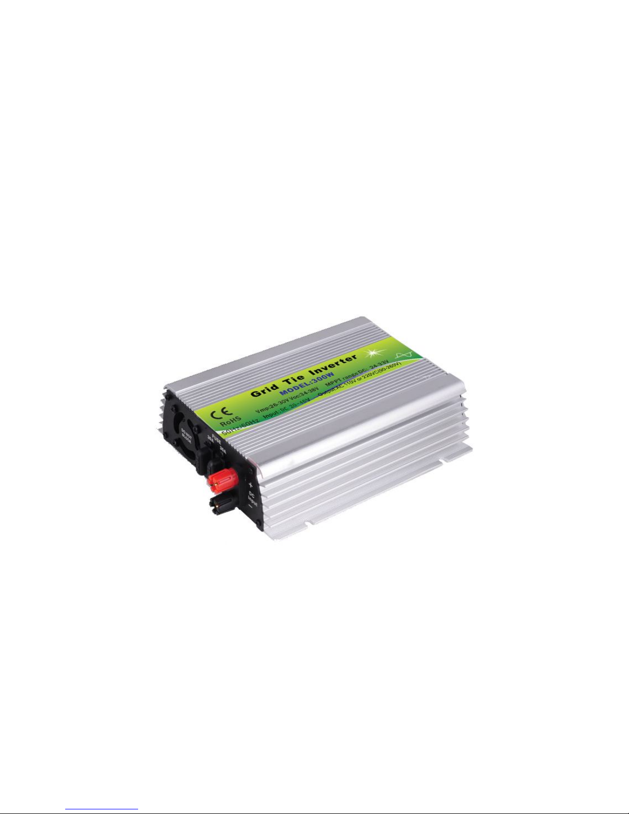
Smart Grid Tie Microinverter
User Manual
Thanks for choosing Smart Microinverters. Read the following instruction
carefully before installation and operating, install and operate as specified
by this user manual strictly to ensure your safe and benefit.
Page 2

Catalogue
Smart Microinverter Introduction…………………………………………………..1
Important Safety Information………………………………………………………2-3
Technical Parameters………………………………………….……………….……..….4
Installation…………………………………………..….…………………..………….….5-6
LED Indicators……………………………………………….…..……………………….....7
General Troubleshooting…………………………..…………………………..……...8
Stack Wiring Diagram……………………………………………………………..………9
Warranty……………………………………………………..……………………….……….10
Warranty Card……………………………….…………………………….………….……..11
Explore Applications Diagram……………..……………………….………….……..13
Any relevant alteration is subject to the latest version without any prior notice.
Page 3

Smart Microinverter Introduction
Smart grid tie inverter is a compact unit, which directly converts direct
current into alternating current for powering appliances and/or office
equipments and connecting to utility grid. The AC output from Smart
Microinverter is synchronized and in-phase with the utility grid. It is a key
device of power generation systems such as PV power generation system,
wind turbine power generation system. Smart Microinverter specially
optimized design to work with modularization of DC power supplies which
includes the mainstream solar modules, 18V (36 cells), 24V (60 cells) and
36V (72 cells) monocrystal and/or Polycrystalline solar panels, wind
turbines and batteries. Smart Microinverters are stabilization, reliable and
high conversion efficiency items. It is the best choice for PV power
generation systems.
Smart Microinverter can be easily placed and attached to the rack
underneath of PV module. No need spaces for independent installation
and low voltage DC wire connects from the PV module to Smart
Microinverter can eliminate the risk of high DC voltage. Distributed
modularization design philosophy for Smart Microinverter insures the
productiveness of the whole system and will not affect by a single point of
failure. Each Smart Microinverter is individually connected to each PV
module in the array. This unique configuration means that an individual
Maximum Peak Power Point Tracker (MPPT) controls each PV modules and
insures that the maximum power available from each PV module is
exported to the utility grid regardless of the performance of the other PV
modules in the array which may be affected by shading, soiling, orientation
or mismatch, etc. Smart Microinverter insures top performance for
maximizing energy production from the whole PV system and gets return
on investment in less time.
1/13
Page 4
Advantages of Smart Microinverter
1. Unique circuit design, choice of import industrial electronic components,
higher efficiency, more stable performance.
2. Creative MPPT technology, efficiency more than 99%, faster and more
sensitive reaction, more reliable.
3. Parallel type design for DC input and modularization design for inverter,
small volume, distributed installation, easy for system configuration,
flexible for combination, strong expansibility of system.
4. Adopting high-frequency isolation transformer type, high efficiency, and
high security.
5. Perfect electrical protection function.
6. Aluminum alloy housing, not rust, heat-resisting and cold-resistant as
well as anti-corrosion.
7. Getting electronic circuit design, appearance design and other core
technology patents.
8. Full output voltage 90-260VAC which includes all countries’ voltage
standard. MCU automatic detection and conversion insures that Smart
Microinverter can work with different AC voltages.
Important Safety Information
Read this First
This manual contains important instructions for use during installation and
maintenance of the Smart Microinverter. To reduce the risk of electrical
shock, and to ensure the safe installation and operation of the Smart
Microinverter, the following safety symbols appear throughout this
document to indicate dangerous conditions and important safety
instructions.
Follow instruction closely.
DANGER! This indicates a hazardous situation, which if not avoided,
will result in death or serious injury.
WARNING! This indicates a situation where failure to follow instructions
may be a safety hazard or cause equipment malfunction. Use extreme
caution and follow instructions carefully.
NOTE: This indicates information particularly important for optimal
system operation.
2/13
Page 5

Do not use Smart Microinverter in a manner not specified by the
manufacturer. Doing so may cause death or injury to persons, or damage to
equipment.
Perform all electrical installations in accordance with all applicable local
electrical codes.
Be aware that only qualified personnel should disassemble and repair the
Smart Microinverters and non-qualified personnel should not install and/or
repair.
Do not attempt to repair the Smart Microinverter; it contains no
user-serviceable parts. If it fails, contact customer service to claim a return
merchandise authorization and start the replacement process. Tampering
with or opening the Smart Microinverter will void the warranty.
If the AC cable connector on the Microinverter is damaged or broken, do not
install the unit.
Before installing or using the Smart Microinverter, read all instructions and
cautionary markings in the technical description and on the Smart
Microinverter System and the PV equipment.
Connect the Smart Microinverter to the utility grid only after you have
completed all installation procedures and after receiving prior approval from
the local electrical utility company.
Be aware that the body of the Smart Microinverter is the heat sink. Under
normal operating conditions, the temperature is 15°C above ambient, but
under extreme conditions the Microinverter can reach a temperature of
75°C. To reduce risk of burns, use caution when working withMicroinverters.
Our suggestion is that do NOT disconnect the PV module from the Smart
Microinverter without first removing AC power when Smart Microinverter
still operation because it may cause of components damaged.
Keep away from children, no touching, no playing so as not to electric shock
when using.
Please installed in place of low humidity and well-ventilated so as to avoid
inverter overheating, as well as clear around the inflammable and explosive
materials.
Safety Instruction
3/13
Page 6
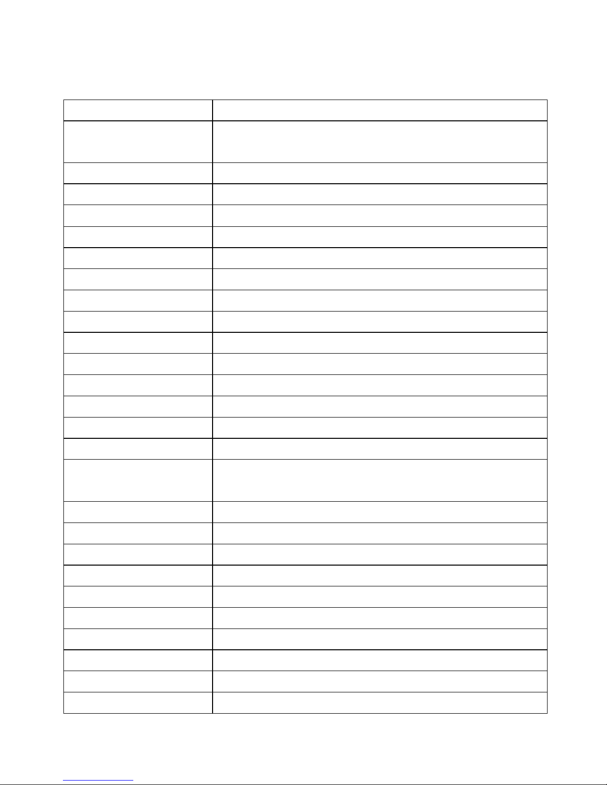
Technical Parameters:
Suitable for 60 cells solar panel which Vmp is 26-30V and Voc is 34-38V.
Rated Power 500W
Compatible with Solar
Panels
500-600W 60 cells
DC Input Range 20-40VDC
MPPT Voltage 24-33VDC
DC MAX. Current 25A
AC Output 120VAC/230VAC(90-260VAC)
Frequency 50Hz/60Hz(Auto control)
Power Factor >97.5%
THD <5%
Phase Shift <2%
Efficiency 120VAC(90-140VAC)
Peak Efficiency 88%
Stable Efficiency 86%
Efficiency 230VAC(190-260VAC)
Peak Efficiency 89%
Stable Efficiency 87%
Protection
Islanding; Short-circuit; Converse Connection; Low Voltage;
Over Voltage; Over Temperature Protection
Working Temperature
-25℃-65℃
Working Humidity 0%~90%RH non-condensing
Waterproof Indoor design
Show Luminous Diode(LED)
Cooling Fan
Stand-by Power
<1W
EMC EN61000-6-3:2007 EN61000-6-1:2007
Grid Disturbance EN 50178+EN 62109-1+VDE0126-1-12
Grid Detection DIN VDE 1026 UL1741
Certificate
CE
4/13
Page 7
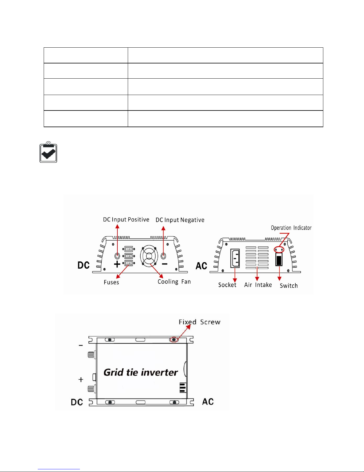
Packing Specification
Packing Accessory Microinverter, AC Cord, User Manual(Warranty Card)
Mechanical Size 21 x 16.5 x 5.3CM
Net Weight/PCS 1.3KGS/PCS
Inner Box (L x W x H)
31 x 21 x 11.5CM
Carton(L x W x H)
42 x 31.5 x 35.5CM, 6PCS/CTN, 8/11KGS
1. Diagrammatize DC input and AC output terminals,
2. Attach the Smart Microinverter to the racking or fix onto the wall,
3. Properly connect the positive and negative of solar panel and Smart
Microinverter,
Installation
5/13
Page 8
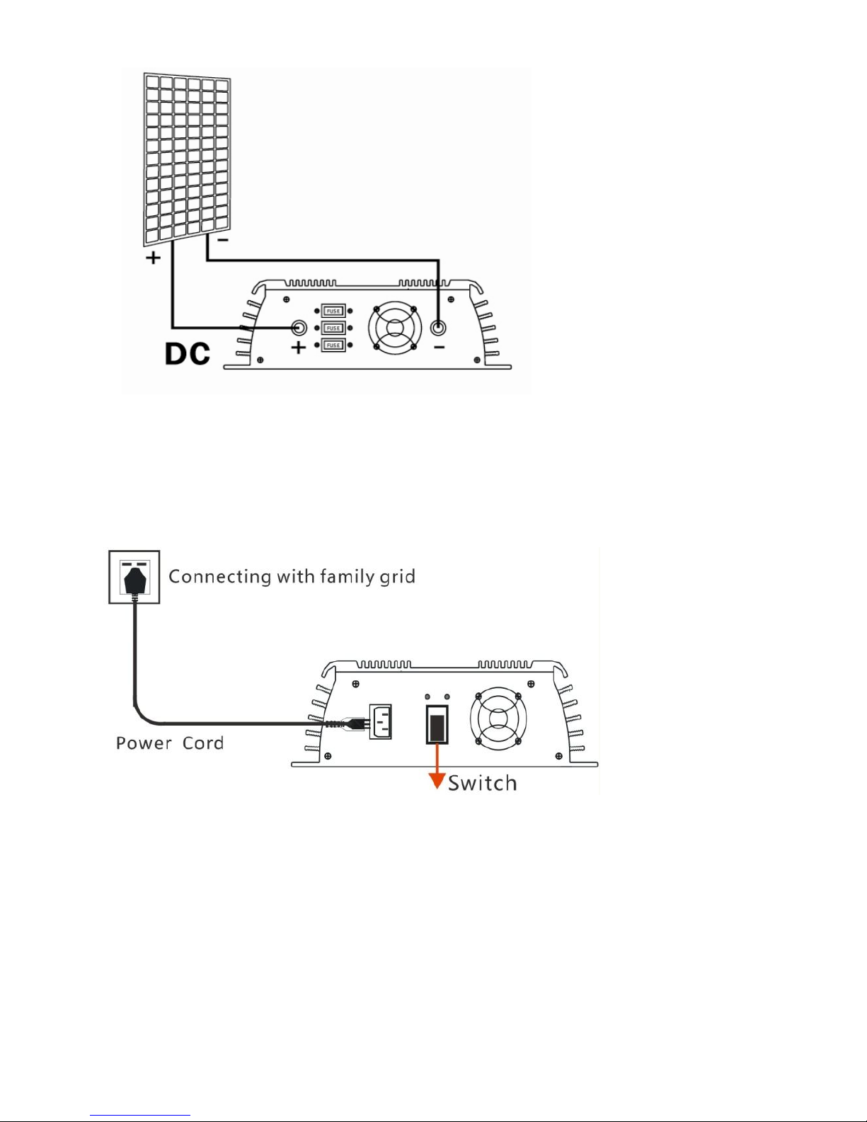
4. AC power cable connects with Smart Microinverter and residential
power grid which refers to low voltage civilian single-phase power
grid.
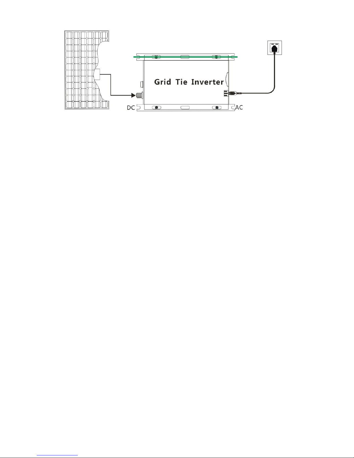
5. Switch on power grid after check for input and output connections are
correct and then switch on the Smart Microinverter. The red and green
LED lights up at the same time and then red LED lights off follow on
and green LED flash fast, it is means that Smart Microinverter is run
for MPPT operation.When green LED long light and it is means that
maximum power point lock-in,Smart Micro inverter proper
functioning and output steady.
6/13
Page 9
LED Indicators
1. Red LED indicator lights up under any conditions include but not
limited:
a) Low-voltage protection (DC input voltage lower than Min. input
voltage of inverters),
b) Over-voltage protection (DC input voltage higher than Max. input
voltage of inverters),
c) Over-temperature protection (inverters will shut down for power
output when temperature of body of inverters higher than 65-70℃,
and inverter will be automatically restart up when temperature
down to 40-50℃),
d) Power grid fault protection when 110VAC or 220VAC grid power
outage and/or tripped,
e) Islanding protection: inverter will be automatically shut down for
power output when disconnect with power grid,
f) Short-circuit protection: inverter stops work when output line
short-circuits,
2. Green LED indicator lights up under any conditions include but not limited:
a) Green LED flash: adjusting for power output, MPPT operating for
tracking,
b) Green LED long light: indicates inverter locking-in Max. output power
operation status,
3. Please note that above operations only run at grid-connected status.
7/13
Page 10

Troubleshooting a non-operating Smart Microinverter
1. System halted and /or without power output
a) Check if switch of Smart Microinverter is turn on or not,
b) Check if the DC connections to Smart Microinverter are correct or
not,
c) Check if any reverse DC connections for positive or negative or not,
d) Check if DC input voltage is within the range of the Smart
Microinverter’s or not,
e) Check if the utility grid voltage and frequency are fit in with the
serviceable range of Smart Microinverter or not,
f) Check if fuses of DC side are fusing or not,
g) Check if utility grid voltage properly connecting to Smart
Microinverters or not.
2.DC power supply is normal but no power output:
a) Check if utility grid voltage is connecting to Smart Microinverter or
not,
b) Check if utility grid voltage is fit in with the serviceable range of
Smart Microinverter or not,
c) Please visual inspection for the LED operation status, red LED will
turn off and green LED will flash or run when inverter connecting
with DC power supply which input voltage is fit in with the range
as specified and power grid properly. If still no power output when
green LED flash or run, probably internal components are
damaged, in such case, please turn the defective inverter back for
further analyze,
d) Please visual inspection for the LED operation status, red LED still
turn on and green LED without any flash or run when inverter
connecting with DC power supply which input voltage is fit in with
the range as specified and power grid properly, probably internal
components are damaged, in such case, please turn the defective
inverter back for further analyze.
8/13
Page 11
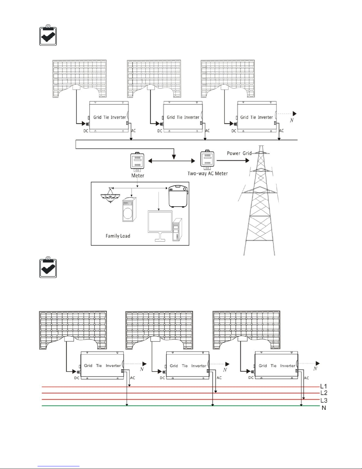
Smart Microinverter Three Phase output Wiring Diagram
Smart Microinverter Stack Wiring Diagram
9/13
Page 12
Warranty
Warranty Conditions
Warranty Period: 15-year limited warranty period.
Warranty Evidence: The B/L,Tracking no, and a completed warranty card.
We grant an implied warranty of 1 year to the inverter from date of purchase
for repair or replace the Defective Product free of charge includes freight
cost. Furthermore, we provides an additional limited warranty for 14 years
for repair or replace the Defective Product free of charge but non-free of
freight charge. If your device has a defect or malfunction during the warranty
period, please also contact our customer service staff or your retailer or
installer.
Warranty claims are excluded for:
• Alterations or repairs to the unit without prior authorization
• Improper use or operation of device
• Improper and non-standard installation
• operating the equipment with defective safety devices
• Impact of foreign objects and force majeure (lightning, surge, storm, fire)
• Inadequate or nonexistent ventilation of the device
• disregarding of safety regulations
• shipping damage
• The Product has been improperly stored or was damaged while in
possession of the Dealer or end user;
WARNING! Only qualified electrical professionals can do the trouble
shooting of the Smart Microinverter system.
WARNING! Please turn off the Smart Microinverter first and then disconnect
the AC grid before disconnecting the Smart Microinverter from the PV
module when remove the inverter from the rack
WARNING: Do not attempt to repair the Smart Microinverter. This may
bring electrical hazard to the person and it will also void the Microinverter
warranty. If troubleshooting methods fail, please contact customer
support to return the Microinverter and initiate for replacement process.
10/13
Page 13
Warranty Card (Invalid Duplicate)
Distributor and/or Sales Representative
Distributor Name
Telephone and/or Email
Sales Representative Date of
Customer
Feedback
Date of finish Disposal Disposal
QC Technician
Others
Name
Country and/or Territory
Telephone
Email
Purchase Channels and/or
Sources
Models
Date of Purchase
Date of Installation
Time of Using
Brief Fault Description
Improvement Suggestions
11/13
Page 14

Other Supplementary Comments or Descriptions from Customers
12/13
Page 15
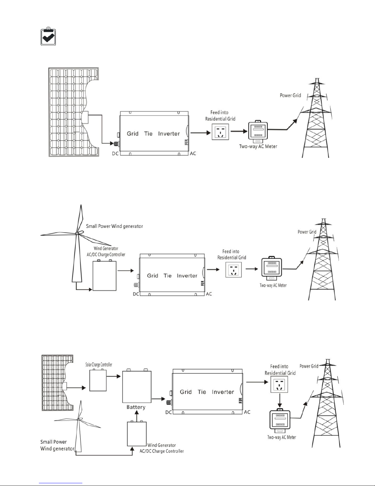
1. Work with 60 cells solar panel(Vmp:26-30V,Voc:34-38V)
2. Work with wind turbine, output DC voltage is fit in with the range as specified
and a 24V or 30V charge controller needed to be used if the wind turbine
without build-in AC TO DC charge controller.
3. Work with battery, PV module and wind turbine charging the battery and
battery discharging to inverter for converting AC power which will feed into
power grid.
Explore Applications Diagram
13/13
 Loading...