

Page 1
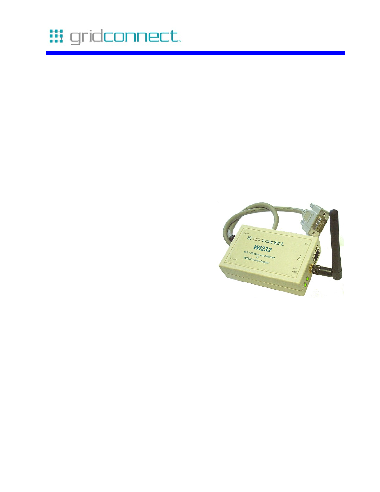
Wi232/WiUSB
Serial to Wireless
Ethernet Adapter
Revision E January, 2008
Document Part Number GC-800-300
Page 2

Page 3

Copyright and Trademark
Copyright © 2004, Grid Connect, Inc. All rights reserved.
No part of this manual may be reproduced or transmitted in any form for any purpose other than the
purchaser's personal use, without the express written permission of Grid Connect, Inc. Grid
Connect, Inc. has made every effort to provide complete details about the product in this manual, but
makes no warranty of any kind with regard to this material, including, but not limited to, the implied
warranties of merchantability or fitness for a particular purpose. In no event shall Grid Connect, Inc.
be liable for any incidental, special, indirect, or consequential damages whatsoever included but not
limited to lost profits arising out of errors or omissions in this manual or the information contained
herein.
Grid Connect, Inc. products are not designed, intended, authorized or warranted for use as
components in systems intended for surgical implant into the body, or in other applications intended
to support or sustain life, or in any other application in which the failure of a Grid Connect, Inc.
product could create a situation where personal injury, death, or severe property or environmental
damage may occur. Grid Connect, Inc. reserves the right to discontinue or make changes to its
products at any time without notice.
Grid Connect and the Grid Connect logo, and combinations thereof are registered trademarks of Grid
Connect, Inc. DSTni is a trademark of Lantronix, Inc. All other product names, company names,
logos or other designations mentioned herein are trademarks of their respective owners.
Wi232 and NETUSB are trademarks of Grid Connect, Inc. XPort is a trademark of Lantronix.
Ethernet is a trademark of XEROX Corporation. UNIX is a registered trademark of The Open
Group. Windows 95, Windows 98, Windows 2000, Windows NT, and Windows XP are trademarks
of Microsoft Corp. Netscape is a trademark of Netscape Communications Corporation.
Grid Connect
1630 W. Diehl Road
Naperville, IL 60563, USA
Phone: 630.245.1445
Technical Support
Phone: 630.245.1445
Fax: 630.245.1717
On-line: www.gridconnect.com
Wi232/WiUSB User Guide i
Page 4

Disclaimer and Revisions
Operation of this equipment in a residential area is likely to cause interference in which case the
user, at his or her own expense, will be required to take whatever measures may be required to
correct the interference.
Attention: This product has been designed to comply with the limits for a Class B digital
device pursuant to Part 15 of FCC Rules. These limits are designed to provide reasonable
protection against harmful interference in a residential installation. This equipment
generates, uses, and can radiate radio frequency energy, and if not installed and used in
accordance with this guide, may cause harmful interference to radio communications.
Changes or modifications to this device not explicitly approved by Grid Connect will void the user's
authority to operate this device.
The information in this guide may change without notice. The manufacturer assumes no
responsibility for any errors that may appear in this guide.
Date Rev. Author Comments
04/19/05 A GR Preliminary Release
08/12/05 B GR Firmware upgrade to 6.0.0.1
07/17/06 C GR Upgrade to 6.2.0.2 and WiPort G
10/05/06 D GR Upgrade to 6.3.0.0. and Web Manager 1.5.0.0
01/14/08 E GR Add mounting holes to board, add DTR/DSR option.
ii Wi232/WiUSB User Guide
Page 5

Warranty
Grid Connect warrants each product to be free from defects in material and workmanship for a
period of ONE YEAR after the date of shipment. During this period, if a customer is unable to
resolve a product problem with Grid Connect Technical Support, a Return Material Authorization
(RMA) will be issued. Following receipt of a RMA number, the customer shall return the product to
Grid Connect, freight prepaid. Upon verification of warranty, Grid Connect will -- at its option -repair or replace the product and return it to the customer freight prepaid. If the product is not under
warranty, the customer may have Grid Connect repair the unit on a fee basis or return it. No services
are handled at the customer's site under this warranty. This warranty is voided if the customer uses
the product in an unauthorized or improper way, or in an environment for which it was not designed.
Grid Connect warrants the media containing software and technical information to be free from
defects and warrants that the software will operate substantially for a period of 60 DAYS after the
date of shipment.
In no event will Grid Connect be responsible to the user in contract, in tort (including negligence),
strict liability or otherwise for any special, indirect, incidental or consequential damage or loss of
equipment, plant or power system, cost of capital, loss of profits or revenues, cost of replacement
power, additional expenses in the use of existing software, hardware, equipment or facilities, or
claims against the user by its employees or customers resulting from the use of the information,
recommendations, descriptions and safety notations supplied by Grid Connect. Grid Connect liability
is limited (at its election) to:
1) refund of buyer's purchase price for such affected products (without interest)
2) repair or replacement of such products, provided that the buyer follows the above procedures.
There are no understandings, agreements, representations or warranties, expressed or implied,
including warranties of merchantability or fitness for a particular purpose, other than those
specifically set out above or by any existing contract between the parties. The contents of this
document shall not become part of or modify any prior or existing agreement, commitment or
relationship.
Wi232/WiUSB User Guide iii
Page 6

Contents
Table of Contents
1. Overview ...........................................................................................................................1-1
1.1 Additional Documentation..................................................................................1-2
1.2 Application Examples.........................................................................................1-3
1.3 Protocol Support .................................................................................................1-4
1.4 Serial RS232 Interface ........................................................................................1-5
1.5 USB Interface...................................................................................................... 1-6
1.6 Power Supply...................................................................................................... 1-6
1.7 Ethernet Interface................................................................................................1-7
1.7.1 LEDs ...................................................................................................1-7
1.8 OEM Board Mounting ........................................................................................1-7
1.8.1 Mounting Holes...................................................................................1-7
1.8.2 Header Connector ...............................................................................1-8
1.8.3 Board Dimensions............................................................................... 1-8
1.9 Product CD..........................................................................................................1-9
1.10 Technical Specifications .................................................................................1-10
2. Quick Start........................................................................................................................2-1
2.1 Required Information..........................................................................................2-1
2.1.1 Hardware Address...............................................................................2-1
2.1.2 WLAN Settings...................................................................................2-1
2.2 Installing and Configuring the Wi232 for WAP................................................. 2-2
2.2.1 Wi232 Configuration - WAP.............................................................. 2-2
2.2.2 Wireless Access Point (WAP) Connection......................................... 2-4
2.3 Installing and Configuring for a Wireless Router............................................... 2-7
2.3.1 Wi232 Configuration - Router............................................................2-7
2.3.2 Network Configuration .......................................................................2-8
2.4 Quick Test.........................................................................................................2-11
3. Configuration Using Web-Manager...............................................................................3-1
3.1 Network Configuration .......................................................................................3-2
3.1.1 Network Mode ....................................................................................3-2
3.1.2 Automatic IP Address Configuration..................................................3-2
3.1.3 Static IP Address Configuration..........................................................3-3
3.1.4 Ethernet Configuration........................................................................3-3
3.2 Server Configuration...........................................................................................3-4
3.3 Serial Tunnel Hostlist Configuration ..................................................................3-5
3.4 Channel 1 Configuration.....................................................................................3-6
3.4.1 Serial Settings .....................................................................................3-6
3.4.2 Connection Settings - TCP..................................................................3-8
3.4.3 Connection Settings - UDP...............................................................3-10
3.5 Email Configuration.......................................................................................... 3-12
3.6 WLAN Configuration .......................................................................................3-12
3.6.1 WLAN Country Setting ....................................................................3-12
3.6.2 WLAN Settings.................................................................................3-13
iv Wi232/WiUSB User Guide
Page 7

3.7 Configurable Pins..............................................................................................3-14
3.8 Apply Settings...................................................................................................3-14
3.9 Apply Factory Defaults .....................................................................................3-15
4. Configuration via Serial Mode or Telnet Port.............................................................. 4-1
4.1 Server Configuration ...........................................................................................4-2
4.2 Channel 1 Configuration .....................................................................................4-3
4.2.1 Baudrate...............................................................................................4-3
4.2.2 I/F (Interface) Mode ............................................................................4-4
4.2.3 Flow.....................................................................................................4-4
4.2.4 Port Number ........................................................................................4-5
4.2.5 Connect Mode .....................................................................................4-6
4.2.6 Send the Escape Sequence (+++) in Modem Mode...........................4-11
4.2.7 Auto Increment Source Port..............................................................4-11
4.2.8 Remote IP Address............................................................................4-11
4.2.9 Remote Port.......................................................................................4-12
4.2.10 DisConnMode..................................................................................4-12
4.2.11 Flush Mode......................................................................................4-13
4.2.12 DisConnTime (Inactivity Timeout).................................................4-14
4.2.13 SendChar 1 and SendChar2.............................................................4-15
4.2.14 Telnet Terminal Type......................................................................4-15
4.2.15 Channel (Port) Password.................................................................4-15
4.3 E-mail................................................................................................................4-15
4.4 WLAN Settings .................................................................................................4-15
4.5 Expert Settings...................................................................................................4-17
4.6 Security Settings................................................................................................4-18
4.6.1 Disable SNMP...................................................................................4-18
4.6.2 SNMP Community Name..................................................................4-18
4.6.3 Disable Telnet Setup..........................................................................4-18
4.6.4 Disable TFTP Firmware Upgrade .....................................................4-19
4.6.5 Disable Port 77FE (Hex) ...................................................................4-19
4.6.6 Disable Web Server...........................................................................4-19
4.6.7 Disable Web Setup ............................................................................4-19
4.6.8 Disable ECHO Ports..........................................................................4-19
4.6.9 Enable Encryption.............................................................................4-19
4.6.10 Enable Enhanced Password.............................................................4-19
4.6.11 Disable Port 77F0h..........................................................................4-19
4.7 Factory Defaults ................................................................................................4-20
4.7.1 Exit Configuration Mode...................................................................4-21
Contents
5. Monitor Mode.................................................................................................................. 5-1
5.1.1 Entering Monitor Mode via the Serial Port .........................................5-1
5.1.2 Entering Monitor Mode via the Network Port.....................................5-1
5.1.3 Monitor Mode Commands...................................................................5-1
6. Updating Firmware......................................................................................................... 6-1
6.1 Obtaining Firmware.............................................................................................6-1
6.1.1 Reloading Firmware............................................................................6-1
6.1.2 Via Device Installer.............................................................................6-1
7. Troubleshooting............................................................................................................... 7-1
7.1.1 Problems and Error Messages .............................................................7-1
Wi232/WiUSB User Guide v
Page 8

Contents
8. Binary to Hex Conversion...............................................................................................8-1
8.1.1 Conversion Table................................................................................ 8-1
8.1.2 Scientific Calculator............................................................................ 8-2
List of Figures
Figure 1 - Serial Tunneling Example.....................................................................................1-3
Figure 2 - Ad-Hoc Network Example....................................................................................1-3
Figure 3 - Serial Tunneling Infrastructure..............................................................................1-4
Figure 4 - Direct Wi232 to Wi232 Connection...................................................................... 1-4
Figure 5 - Wi232 Connection.................................................................................................2-2
List of Tables
Table 1 - RS232 Signals.........................................................................................................1-5
Table 2 - USB Signals............................................................................................................1-6
Table 3 - OEM Header Wiring...............................................................................................1-8
Table 3 - Technical Specs ....................................................................................................1-10
vi Wi232/WiUSB User Guide
Page 9
1. Overview
Wi232 is a wireless embedded device server that provides serial-to-wireless network connectivity. Wi232
allows virtually any RS232 serial device or equipment to be remotely accessed, controlled, monitored or
shared on an 802.11b wireless network.
The Wi232 functions independently of a PC, providing a fully integrated solution that combines a processor,
memory, 802.11b transceiver, Ethernet port, and a high-speed serial port into a single compact module. It
includes an operating system, an embedded Web server, full TCP/IP protocol stack and WEP/WPA security.
In addition, the Wi232 supports numerous other network communication protocols, including ARP, UDP,
TCP, ICMP, Telnet, AutoIP, DHCP, HTTP, SNMP, and SMTP.
For designers who wish to customize the user interface by employing common and familiar tools, the Wi232
serves applets to a Web browser, resulting in interactive Web pages. This customization of HTML Web
pages and configuration screens tailors the Wi232 to fit unique requirements.
The Wi232 device server has the following capabilities:
• Communication between TCP and UDP to serial.
• Wireless interface (802.11b or Ethernet interface.
• Upgradeable firmware.
• SNMP monitoring.
• Connects devices through a TCP or UDP data channel to computers or to another de vice server.
• Contains a web server allowing presentation of custom content and easy configuration through the
browser.
Some of the devices are:
• ATM Machines
• CNC Controllers
• Data Collection Devices
• Universal Power Supply (UPS) Management Units
• Telecommunications Equipment
• Data Display Devices
• Security Alarms and Access Control Devices
• Handheld Instruments
• Fire Control Panels
• Time/Attendance Clocks and Terminals
• Virtually any RS-232 serial device
Wi232/WiUSB User Guide 1-1
Page 10

1.1 Additional Documentation
The following guides are available on the product CD.
Title Description File Name
Wi232/WIUSB
User Guide
Device Installer
User Guide
Quick Start Guide
Comm Port
Redirector Guide
Web Enable User
Guide
GPIO Interface
Guide
UDP Configuration
Guide
Tech Notes
This manual in PDF format. Wi232_UM_800300_x.pdf
Information about installing and using
Dev_Inst_UG_800233_x.pdf
Device Installer Utility.
Quick steps to get the Wi232 up and
QuickStart_800234_x.pdf
running fast.
Provides information on using the
Redirector_UG_800235_x.pdf
Windows based utility to create a
virtual com port.
Explains the steps to get your device
Web_Enabling_UG_800236_x.pdf
Web enabled.
Introduction to the GPIO interface and
GPIO_800237_x.pdf
a demo program.
How to use UDP to configure the unit.
UDPconfig_800238_x.pdf
How to acquire and use setup records
to configure a unit.
Additional information to aid in using
Tech_Notes_800239_x.pdf
the Wi232/WIUSB.
1-2 Wi232/WiUSB User Guide
Page 11
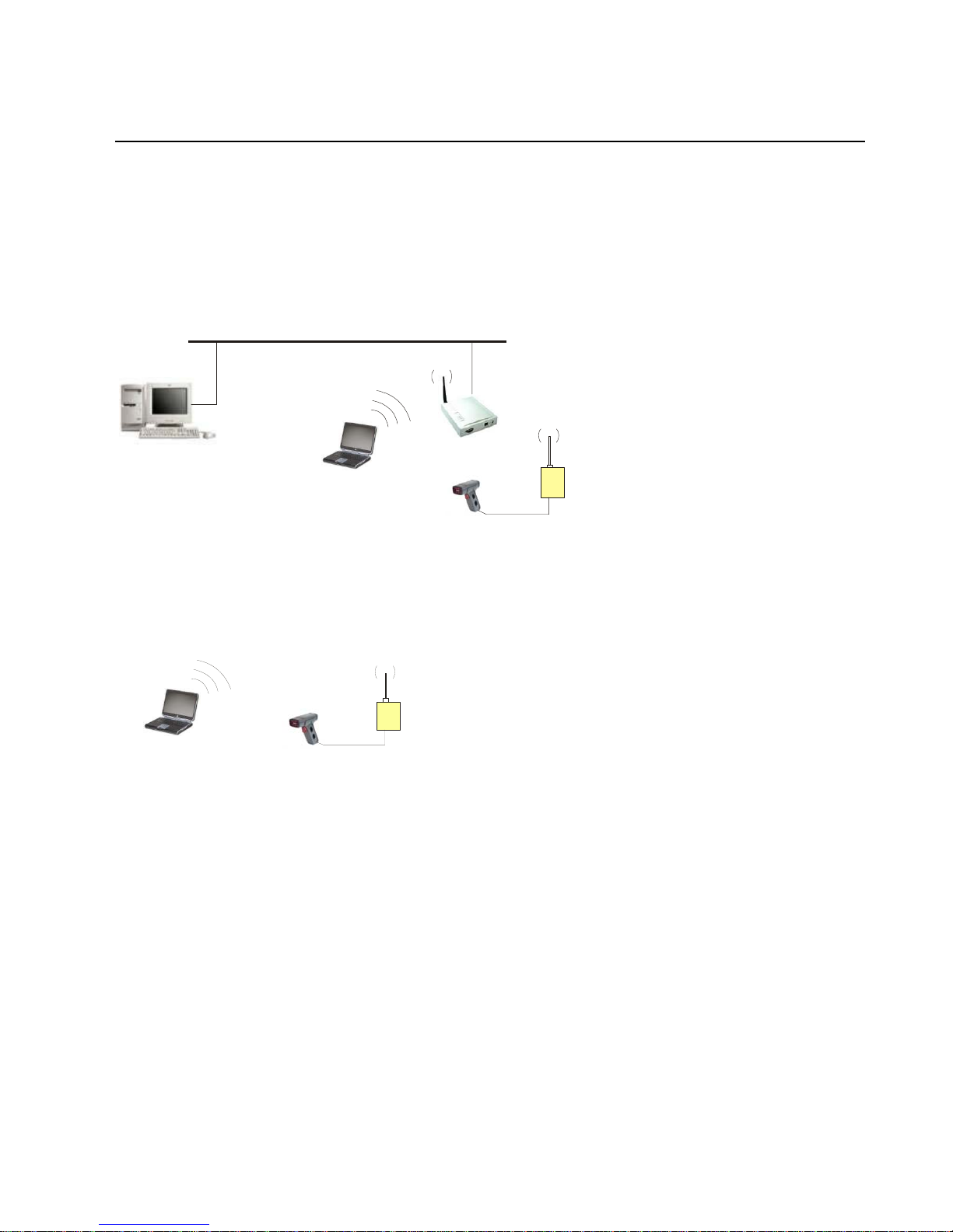
1.2 Application Examples
The Wi232 has a serial port, an Ethernet port and an 802.11b transceiver. You can enable either the Ethernet
port or the Wireless LAN. The serial port connects to the serial communication port of your device. The
wireless transceiver connects to another wireless device or to an Access Point (AP) connecting to a network
through an Ethernet link.
This section includes four typical scenarios for using the Wi232.
Figure 1 - Serial Tunneling Example
Ethernet
Personal Computer (PC)
Wireless Laptop Wi232
POS Device
A PC connected to an Access Point via an Ethernet connection and a laptop with a wireless connection to
the Access Point LAN access the Wi232 as though they are directly connected to it. The combination of the
Wi232, a PC, and Redirector software allows the PC to directly communicate to the Wi232’s serial devices,
providing wireless serial tunneling.
Figure 2 - Ad-Hoc Network Example
Wireless Laptop
POS Devi ce
Wi232
In the above example, the Access Point is not present. The laptop makes a direct wireless connection with
the Wi232 to manage serial devices. Without an AP, it is a peer-to peer relationship.
Wi232/WiUSB User Guide 1-3
Page 12
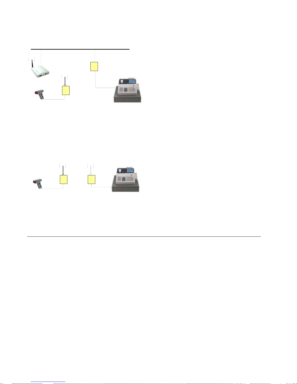
t
Figure 3 - Serial Tunneling Infrastructure
Etherne
NET232
Serial to Ethernet
Adapter
Wi232
Wireless
Serial to Ethernet
POS Device
Adapter
POS Device
In the above example, the Wi232 communicates with another device server via the Access Point. The
NET232 device server, in this example, is connected via an Ethernet connection to the Access Point. As
such, the Wi232 and the device server communicate directly and can transfer information between their
serial devices. This configuration is called Infrastructure mode.
Figure 4 - Direct Wi232 to Wi232 Connection
Wi232
Wireless
Serial to Ethernet
Adapters
POS Device
POS Device
In the above example, two Wi232s have established an Ad-Hoc peer-to-peer relationship. They
communicate directly to each other’s serial devices without a PC or an Access Point.
Note: How do you set up the units for point-to-point? See Application Note, Wi232 Serial Tunnel, GC-800-302.
1.3 Protocol Support
The Wi232 uses the Internet Protocol (IP) for network communications and the Transmission Control
Protocol (TCP) to assure that no data is lost or duplicated, and that everything sent to the connection arrives
correctly at the target.
Other supported protocols include:
• ARP, UDP, TCP, ICMP, Telnet, TFTP, AutoIP, DHCP, HTTP, and SNMP for network
communications and management.
• TCP, UDP, and Telnet for connections to the serial port.
• TFTP for firmware and web page updates.
• IP for addressing, routing, and data block handling over the network.
• User Datagram Protocol (UDP) for typical datagram applications in which devices interact with
other devices without maintaining a point-to-point connection.
1-4 Wi232/WiUSB User Guide
Page 13
1.4 Serial RS232 Interface
The table below lists the RS232 signals for the Wi232. The RS232 interface is a 9-pin Male D-style
connector (DB9M), configured as a DTE device. DCE configured devices are also available on special
order.
Table 1 - RS232 Signals
Wi232 Signal Direction DTE DB-9 Male
Pin #
DCE DB-9
Female Pin #
Data Out (TXD) Out 3 2
Data In (RXD) In 2 3
Ground 5 5
RTS In 8 7
CTS Out 7 8
DTR Use J5 to
4 6
jumper 4-6
DSR Use J5 to
6 4
jumper 4-6
Note: J5 is used to jumper cable pins 4 to 6, which ties DTR to DSR. To locate J5, open the case by removing the two
screws. Use the drawing below to locate the jumper.
J5
J5 is used to ti e D S R
to DTR. Used only with
a wired cable. Signals
are NOT available on the
option header.
+
Wi232/WiUSB User Guide 1-5
Page 14

1.5 USB Interface
The table below lists the USB signals for the WiUSB. The USB cable is a Type A Male connector.
Table 2 - USB Signals
Pin # Description
1 - RED VBUS
2 - WHITE D-
3 - GREEN D+
4 - BLACK GND (Ground)
1.6 Power Supply
The Wi232 can use any DC power source from 9VDC to 24VDC. A typical power cube sent with the unit is
a 9VDC, 500 mA, 8W power cube. However, there are other units that can be used as long as they are in the
range of 9-24VDC and supply the proper wattage.
The Wi232 power adapter is a 2.1mm, positive center power jack. The jack is equivalent to a CUI Inc. PJ002A power jack.
You can also order the Wi232 with a Phoenix right angle power connector. The unit is supplied with a
mating Phoenix terminal block plug.
1-6 Wi232/WiUSB User Guide
Page 15
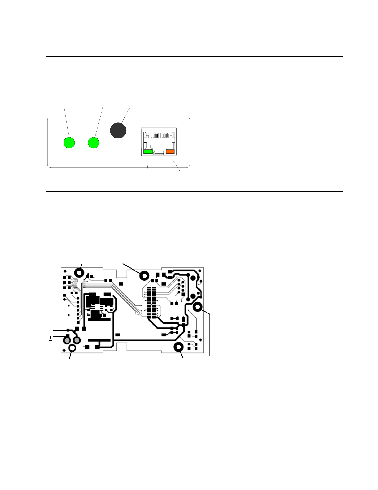
1.7 Ethernet Interface
1.7.1 LEDs
The device contains the following LEDs:
Power
LAN Activity
Antenna
Jack
Activity
Link
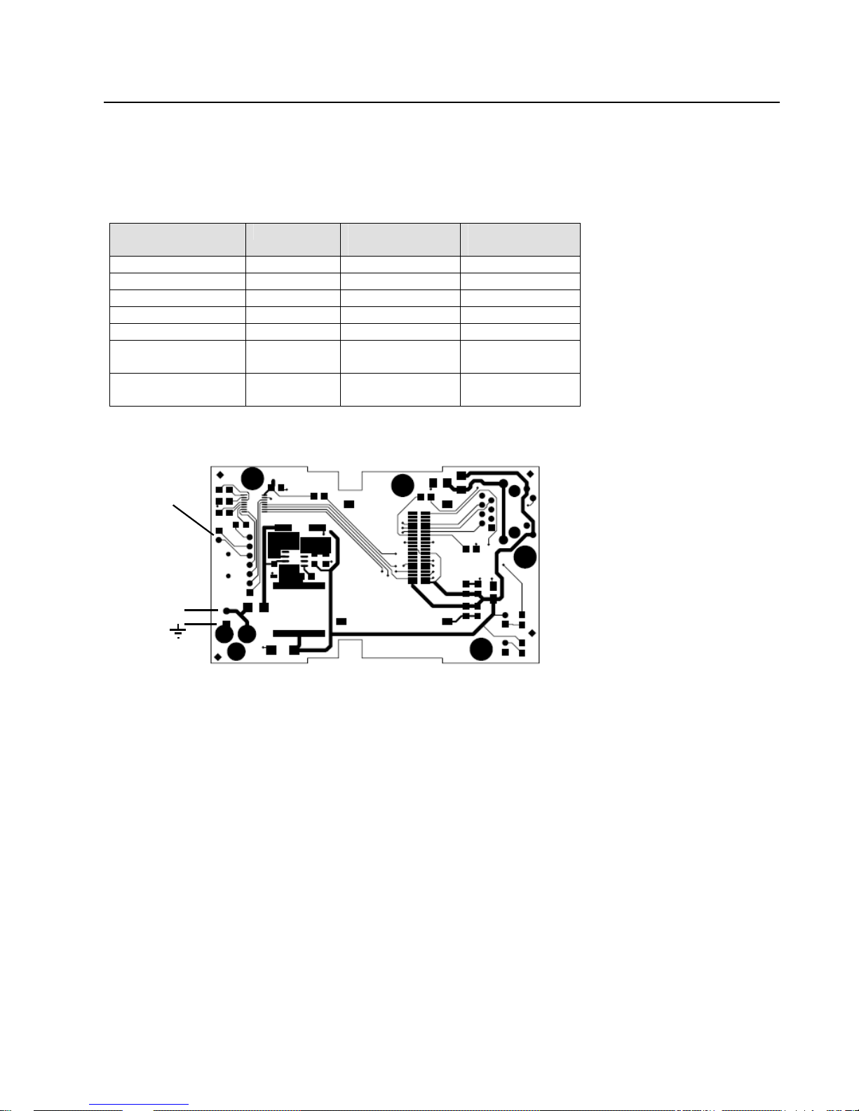
1.8 OEM Board Mounting
If you order the Wi232 as an OEM board, you can mount the board to your device and connect the signal
wires using the following drawings.
1.8.1 Mounting Holes
The following drawing shows the mounting holes for the Wi232 OEM board. If the power jack is removed,
one of the holes can be used for mounting the board.
125mil (3.175mm)
+
130mil (3.302mm)
Can be used if the power
jack is not installed.
Wi232/WiUSB User Guide 1-7
125mil (3.175mm)
Page 16
1.8.2 Header Connector
The header solder pads are located on the bottom layer of the board. The following drawing shows the
location of the pads. Note the part number and source for the connector header and receptacle. Use .250”
standoffs for proper spacing.
HEADER FOR SIGNALS
AND POWER IF BOARD
IS MOUNTED WITH
STANDOF FS.
Pin 2
Pin 1
BOTTOM LAYER
Connector Header
10-Pos, 2mm
Vert SMD
Mfg# 87759-1050
Digi-Key: WM18652-ND
(Part for Wi232)
Connector Receptacle
10-Pos, 2mm V ert PC Board
Mfg# 79107-7004
Digi-Key: WM18676-ND
(Circuit Board Part)
The pads are wired according to the following table.
Table 3 - OEM Header Wiring
Pin # Description
1 Ground
2 Ground
3 CTS (Out)
4 Ground
5 RTS (In)
6 Ground
7 TXD (Out)
8 V + (In)
9 RXD (In)
10 V+ (In)
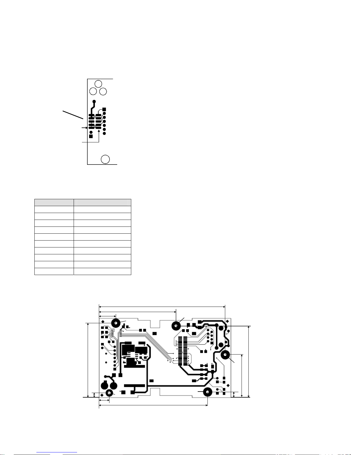
1.8.3 Board Dimensions
The dimensions for the mounting holes are shown in the following drawing.
0.450
2.000
A=125mil (3.175mm) Large Pads
B=130mil (3.302mm) Small Pad
also used for one terminal of the
power jack.
0.125
1-8 Wi232/WiUSB User Guide
B
0.275
2.075
A
A
A
2.925
3.400
1.925
1.150
A
0.150
Page 17

1.9 Product CD
The product CD sent with the Wi232/WIUSB contains Device Installer software, ComPort Redirector,
SetZone Utility, USB Device Drivers, Application Notes and technical documents.
The CD contains Virtual COM Port Drivers for the NETUSB device.
Wi232/WiUSB User Guide 1-9
Page 18

1.10 Technical Specifications
Table 4 - Technical Specs
Category Description
CPU
Firmware Upgradeable via TFTP and serial port
Reset Circuit Reset In is low active. (Software reset only)
Serial Interface RS232. Baudrate software selectable (300 to 921600)
USB USB Type A Male connector. USB Specification 2.0 Compliant, Full Speed (12Mbps).
Serial Line Formats 7 or 8 data bits, 1-2 Stop bits, Parity: odd, even, none
Flow Control XON/XOFF (software), CTS/RTS (hardware), None
Network Interface Wireless 802.11b, 802.11g and 10/100 Ethernet
Compatibility Ethernet: Version 2.0/IEEE 802.3
Protocols Supported ARP, UDP, TCP, Telnet, ICMP, SNMP, DHCP, BOOTP, Auto IP, TFTP, SMTP, and
Data Rates With
Automatic Fallback
Medial Access Control CSMA/CA with ACK
Distance Up to 328 feet indoors
Modulation OFDM, DSSS, CCK, DQPSK, DBPSK, 64 QAM, 16 QAM
Transmitter 2.412 – 2.484 GHz, 14dBm +1.5 dBm/-1.0 dBm
Receive Level -10dBm (with PER < 8%)
Average Power
Consumption
Power Input 9VDC to 24VDC.
LEDs RJ45 Jack: GRN: Ethernet Act, YEL: Link.
Management Internal web server, Device Installer Software, Serial login, Telnet login
Security Password protection, Locking features, 64/128 bit WEP, WPA, 802.11i/WPA2
Internal Web Server Serves static web pages and Java applets. Storage capacity: 1.2MB or 19 pages of 64K
Dimensions 2.42”w x 3.80”h x 1.025”d (See the wi232_wall_plate.pdf drawing on the CD)
Weight 5.4oz (with antenna)
Material Case: Flame Retardant
Temperature Operating range: -40°C to +70°C, Storage range: -40°C to +85°C (-40°F to 185°F)
Relative Humidity Operating: 5% to 95% non-condensing
Warranty 1-year limited warranty
Included Software Windows™ 98/NT/2000/XP based Device Installer configuration software, Windows™
EMI Compliance
DSTni-EX 186 CPU, 256 KB zero wait state SRAM
2048KB Flash, 16KB Boot ROM
Baud rates: 300bps to 921.6Kbps.
512 Byte Receive Buffer, 512 Byte Transmit Buffer.
Virtual COM Port Device Drivers for Win 98/2000/XP, Win CE, Linux 2.40
HTTP, CSMA/CA with ACK
54Mbps — 1Mbps
WiPort-G 1300 mW (WLAN mode;maximum data rate)
300 mW (WLAN mode;idle)
750 mW (Ethernet mode)
Wi232 Module: 150ma @12VDC
9VDC, 500 mA, 8W External Adapter Included. 120VAC (USA) or 100-240VAC
Universal with adapters.
Case: GRN: Power, GRN: WLAN Activity
each. Extended range WiPort has 51 pages of 64K per page.
based Comm Port Redirector and USB device drivers.
Radiated & conducted emissions - complies with Class B limits of EN 55022:1998
Direct & Indirect ESD - complies with EN55024:1998
RF Electromagnetic Field Immunity - complies with EN55024:1998
Power Frequency Magnetic Field Immunity - complies with EN55024:1998
1-10 Wi232/WiUSB User Guide
Page 19

2. Quick Start
This section describes a procedure for quickly installing the Wi232 through the serial port.
2.1 Required Information
2.1.1 Hardware Address
You need to know the unit's hardware address (also known as MAC address), which is on the manufacturers
ID label on the bottom of the unit. It is in the format: 00-20-4a-XX-XX-XX, where the XXs are unique
numbers assigned to the product.
Hardware Address: 00-20-4a- ____ - ____ - ____
2.1.2 WLAN Settings
Your Wi232 must have a unique IP address on your network. The systems administrator generally provides
the IP address and corresponding subnet mask and gateway. If you leave the IP address set to 0.0.0.0, the
Wi232 will attempt to get a DHCP address from the wireless Access Point or network server. If it cannot get
a DHCP address, it will use AutoIP to assign an IP address.
Before the Wi232 can communicate on an 802.11b wireless network, the WLAN settings must match the
wireless network. By default, the Wi232 is set to Infrastructure network mode and its wireless Network
Name (SSID) is LTRX_IBSS. You will need to change the Network Name (SSID) to the name used by
your wireless Router or Access Point.
IP Address: _____ _____ _____ _____
Subnet Mask: _____ _____ _____ _____
Gateway: _____ _____ _____ _____
WLAN SSID ________________________ (case sensitive)
WEP Enabled Y/N _________
WEP Key 64 bit or 128 bit? ________
WEP Key: ______________________________________
(Entered in HEX format (0-9 A-F) xx-xx-xx-xx-xx-xx-xx-xx-xx-xx-xx-xx-xx)
Wi232/WiUSB User Guide 2-1
Page 20
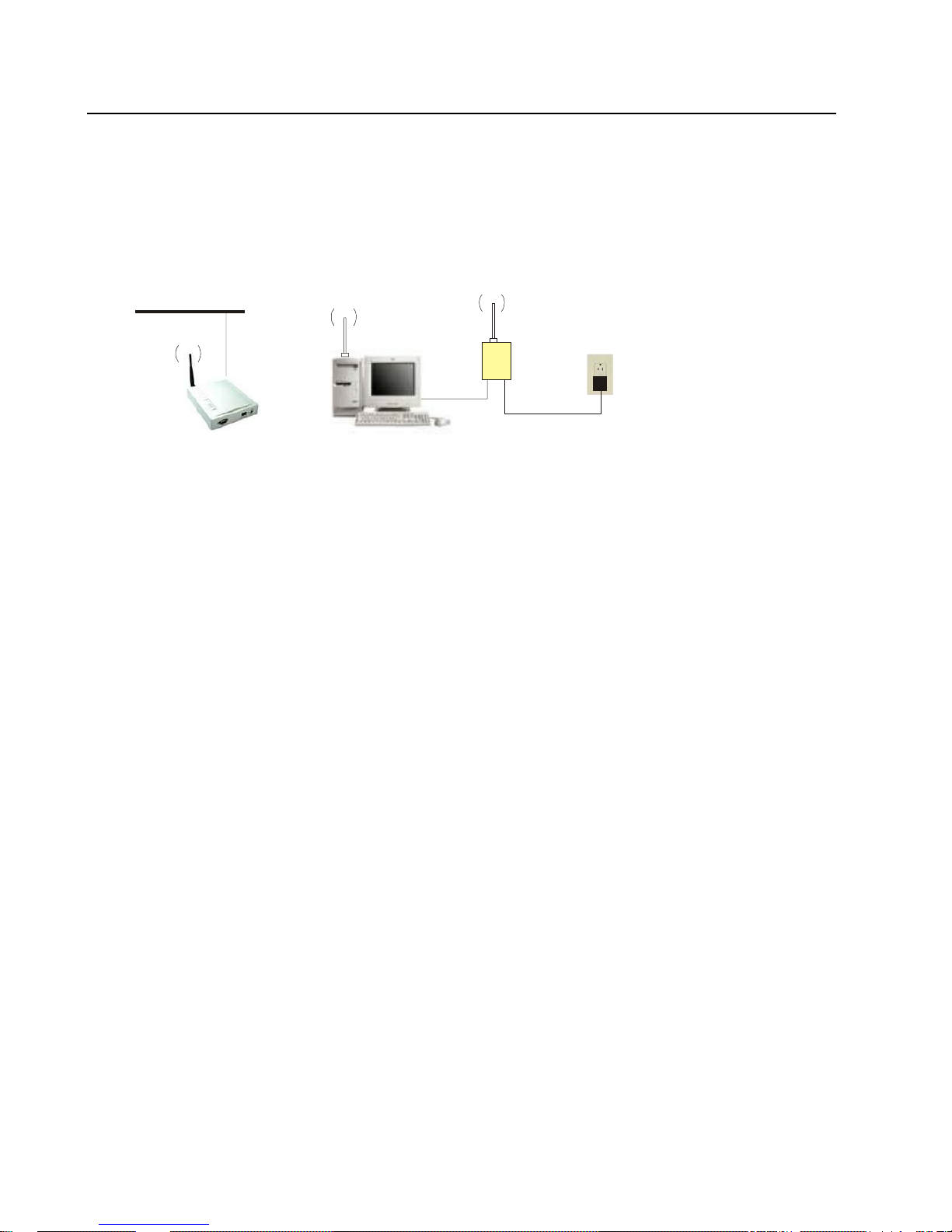
2.2 Installing and Configuring the Wi232 for WAP
Complete the following steps to connect and initially configure the Wi232. Initial configuration is done
using the Serial Mode’s Setup menu. The following drawing shows a Wireless Access Point (WAP) that
links the PC and the Wi232. A Wireless Access Point generally requires a password and a security access
code to enable network access, so you should have this information before starting the configuration
process.
Figure 5 - Wi232 Connection
Ethernet
Wi232
Wireless Access Point (WAP)
COM
Personal Computer (PC)
Power
2.2.1 Wi232 Configuration - WAP
1. Connect a null modem cable to the Wi232’s serial port. (Null Modem Adapter supplied)
2. Connect the other end of the serial cable to a PC’s serial COM port.
3. On the PC, open a terminal emulation application (e.g. HyperTerminal). The default serial settings are: 9600
baud, 8 bits, not parity, 1 stop bit and no flow control(9600, 8, N, 1).
Note: The default settings are always the same for the first 5 seconds of startup.
4. Enter Setup Mode by connecting the power supply and holding down the lower case x key. (valid for 5 seconds)
5. Upon connection , the foll owing information displa ys:
MAC address 00204A8245A8
Software version V6.3.0.0. (060821)
AES library version 1.8.2.1
Press Enter for Setup Mode
Press Enter within 5 seconds to display a list of all the settings. The Change Setup menu will be displayed
at the end of the current settings list. A prompt message will be displayed at the end of the options list.
Change Setup:
0 Server
1 Channel 1
2 Channel 2
3 E-mail
4 WLAN
5 Expert
6 Security
7 Factory defaults
8 Exit without save
9 Save and exit Your choice ?
Two settings are required for the Wi232 to communicate on a wireless network:
• The Server settings: IP address, subnet mask, gateway, etc.
• The WLAN settings: topology, network name, security code, etc.
2-2 Wi232/WiUSB User Guide
Page 21

6. To configure the Server settings, type 0 at the prompt and press Enter. The first prompt allows you to sele ct a Wired
Only network, a Wireless Only network, or Bridging.
Network Mode (0=Wired Only 1=Wireless Only 2=Bridging(One Host)): (0) ?
a) Enter 1 for a Wireless Only network.
Edit the following fields:
Note: Current settings are displayed in parentheses.
b) IP Address: the IP address must be set to a unique value in the network. Enter each octet and
press Enter between each section. The following example shows the IP address set to
172.20.206.120.
Note: If you leave the IP address set to 0.0.0.0, you will enable DHCP. You will need to run Device Installer or some
other utility to determine the IP address of the Wi232.
IP Address : (000) 172(Enter).000 20(Enter).000 206(Enter).000 120(Enter)
c) Set Gateway IP Address: the gateway address should be the IP address of the router connected to
the same LAN segment as the Wi232 unit. If there is no router, press Enter to accept the default.
Set Gateway IP Address (N) ? Y
Gateway IP addr (000) .(000) .(000) .(000)_
d) Netmask: a netmask defines the number of bits taken from the IP address that are assigned for the
host part.
Netmask: Number of Bits for Host Part (0=default) (8)
e) Change Telnet Configuration Password: change the Telnet configuration password to prevent
unauthorized access to the Setup Menu.
Change telnet config password (N) ?
f) Change DHCP device name.
Change DHCP device name (not set) ? (N) ?
7. To configure the WLAN settings , type 4 at the prompt and press Enter. Edit the foll owing fields:
a) Topology set to Infrastructure or Adhoc: Select 0 for Infrastructure and press Enter.
Topology 0=Infrastructure, 1=Adhoc (0) ?
b) Network Name (SSID) (LTRX_IBSS): The default setting is LTRX_IBSS. Type the name to
match your network name. This is a case-sensitive field and must match exactly. The following
example shows a new name.
Network name (SSID) (GRIDCONNECT) ?
c) Security: The default setting is 0 = none. Press the Enter key to accept the default setting. It is
highly recommended that once you have your network configured, you return to this menu and
select one of the security options.
Security suite 0=none, 1=WEP, 2=WPA 3=WPA2/802.11i(0) ? _
d) TX Data rate: The default setting is automatic data rate.
TX Data rate 0=fixed, 1=auto fallback (1) ?
e) TX Data Rate: Select a fixed data rate.
Wi232/WiUSB User Guide 2-3
Page 22
TX Data rate: 0=1, 1=2, 2=5.5, 3=11, 4=18, 5=24, 6=36, 7=54 Mbps (3)
f) Power Management: The default setting allows the Wi232 to run at the fastest rate. Press the
Enter key to accept the default setting.
Enable power management (N) ? _
8. Upon completing the IP and WLAN settings configuration, type 9 at the prompt and press Enter to save the setup
parameters and exit the Wi232 Serial Mode setup.
Parameters stored ...
9. The Wi232 is ready for wireless connection.
2.2.2 Wireless Access Point (WAP) Connection
In the following example, a Wireless Access Point was assigned the network name of GRIDCONNECT.
Verify your wireless adapter is inserted correctly in the PC or laptop. Ensure the wireless adapter’s drivers
and utilities are installed.
Go to Start/Settings/Network Connections and verify your wireless adapter is enabled. Right click on the
connection and select Properties.
2-4 Wi232/WiUSB User Guide
Page 23
In the following example, an Orinoco wireless adapter is used.
Select Internet Protocol (TCP/IP) from the list.
Click the Properties button.
Set the adapter to obtain an IP address automatically from the Wireless Access Point.
Wi232/WiUSB User Guide 2-5
Page 24
Open the client manager for the wireless adapter to setup a configuration profile. You can generally access
the client manager icon in the tool tray.
Verify the client manager has the following settings:
• Connected to network: GRIDCONNECT (or your specific network name)
Verify that the wireless adapter is connected to the Access point and has a good signal.
At this point, you should be able to access the Wi232 through a wireless connection.
• If you assigned the Wi232 an IP address, you can use the Web-Manager in Device Installer to
configure the unit to work with your application. Before you do that, you may want to try the Quick
Test in the next section to verify the unit can send and receive data between the serial port and the
Ethernet port. Continue with Configuration Using Web-Manager on page 3-1.
• If you did NOT assign an IP address, and allowed the unit to acquire a DHCP or AutoIP address,
then you will need to locate the unit on the network and determine the IP address. The best way to
locate the unit is with the Device Installer utility included on the software CD. Please read the
Device Installer User Guide, Dev_Inst_UG_800233_x.pdf, before installing the software.
• Once you determine the IP address, try the Quick Test in the next section to verify the unit can send
and receive data between the serial port and the Ethernet port. You can continue to configure the
device by going to Configuration Using Web-Manager on page 3-1.
To configure the Wi232 with a serial port connection, see Configuration via Serial Mode or Telnet Port on
page 4-1.
2-6 Wi232/WiUSB User Guide
Page 25

2.3 Installing and Configuring for a Wireless Router
When using a wireless Router, you must have all the system components on the same subnet. This can be
done by using the setup procedure for your Router and noting the IP address and subnet mask used for the
configuration. If your router does not have DHCP enabled, you will have to assign the IP address to various
system components to make them work with the router.
2.3.1 Wi232 Configuration - Router
The Wi232 is configured slightly different for a router. Some routers do not provide a DHCP service. In this
case, you must enter an IP address that is in the same subnet as the router. Follow the setup procedure as
described in Installing and Configuring the Wi232 on page 2-2 to display the serial setup menu.
1. To configure the Server settings, type 0 at the prompt and press Enter. The first prompt allows you to select
a Wired Only network, a Wireless Only network, or Bridging.
Network Mode (0=Wired Only 1=Wireless Only 2=Bridging(One Host)): (0) ?
a) Enter 1 for a Wireless Only network.
Edit the following fields:
b) IP Address: the IP address must be set to a unique value in the network. Enter each octet and
press Enter between each section. The following example shows the IP address set to
192.168.2.101.
IP Address : (000) 192(Enter).000 168(Enter).000 2(Enter).000 101(Enter)
c) Set Gateway IP Address: the gateway address should be the IP address of the router connected to
the same LAN segment as the Wi232 unit. If there is no router, press Enter to accept the default.
The example shows the gateway set to 192.168.2.1.
Set Gateway IP Address (N) ? Y
Gateway IP addr (000) 192(Enter).000 168(Enter).000 2(Enter).000 1(Enter)
d) Netmask: a netmask defines the number of bits taken from the IP address that are assigned for the
host part. For the IP address shown above, the netmask is 255.255.0.0. The number of bits is 16.
Netmask: Number of Bits for Host Part (0=default) (16)
2. To configure the WLAN settings , type 4 at the prompt and press Enter. Edit the foll owing fields:
a) Topology set to Infrastructure or Adhoc: Select 0 for Infrastructure and press Enter.
Topology 0=Infrastructure, 1=Adhoc (0) ?
b) Network Name (SSID) (LTRX_IBSS): The default setting is LTRX_IBSS. Type the name to
match your network name. This is a case-sensitive field and must match exactly. The following
example shows a new name.
Network name (SSID) (PUBLIC) ?
c) Security: The default setting is 0 = none. Press the Enter key to accept the default setting. It is
highly recommended that once you have your network configured, you return to this menu and
select one of the security options.
Security suite 0=none, 1=WEP, 2=WPA, 3=WPA2/802.11i (0) ? _
d) TX Data rate: The default setting is automatic data rate.
Wi232/WiUSB User Guide 2-7
Page 26

TX Data rate 0=fixed, 1=auto fallback (1) ?
e) TX Data Rate: Select a fixed data rate.
TX Data rate: 0=1, 1=2, 2=5.5, 3=11, 4=18, 5=24, 6=36, 7=54 Mbps (3)
f) Power Management: The default setting allows the Wi232 to run at the fastest rate so press the
Enter key to accept the default setting.
Enable power management (N) ? _
3. Upon completing the IP and WLAN settings configuration, type 9 at the prompt and press Enter to save the setup
parameters and exit the Wi232 Serial Mode setup.
Parameters stored ...
4. The Wi232 is ready for wireless connection.
2.3.2 Network Configuration
Verify your wireless adapter is inserted correctly in the PC or laptop. Ensure the wireless adapter’s drivers
and utilities are installed.
Go to Start/Settings/Network Connections and verify your wireless adapter is enabled. Right click on the
connection and select Properties.
2-8 Wi232/WiUSB User Guide
Page 27

In the following example, an Orinoco wireless adapter is used.
Select Internet Protocol (TCP/IP) from the list.
Click the Properties button.
Set the adapter to an address compatible with your router. In the example below, the router base address is
192.168.2.xxx. In the following dialog box, the IP, subnet and gateway addresses match the base address of
the router.
Wi232/WiUSB User Guide 2-9
Page 28

Open the client manager for the wireless adapter to setup a configuration profile. You can generally access
the client manager icon in the tool tray.
Verify the client manager has the following settings:
• Connected to network: PUBLIC (or your specific network name)
• Channel 11 (or specified channel)
Verify that the wireless adapter is connected to the router and has a good signal.
At this point, you should be able to access the Wi232 through a wireless connection.
Note: Try the Quick Test in the next section to verify the unit can send and receive data between the serial port and the
Ethernet port. You can continue to configure the device by going to Configuration Using Web-Manager on page 3-1.
To configure the Wi232 with a serial port connection, see Configuration via Serial Mode or Telnet Port on
page 4-1.
2-10 Wi232/WiUSB User Guide
Page 29

2.4 Quick Test
This quick test is designed to demonstrate the following:
• The ability of the unit to move data from the serial port to the Ethernet port
• The ability of the unit to move data from the Ethernet port to the serial port
Serial Session
Start a session of HyperTerminal or other terminal emulation program. Enter a name for the new connection
and click OK. Example: SERIAL
In the Connect To dialog box, go to the Connect using field and select the serial Com port that is
connected to the Wi232 and click OK.
In the COMx Properties dialog box, enter 9600, 8, None, 1, None and click OK. This is the RS232 serial
port terminal.
Wi232/WiUSB User Guide 2-11
Page 30

The status message at the bottom of the Hyper Terminal screen should show it is connected.
TCP/IP Session
Start another session of HyperTerminal. Enter a name for the new connection and click OK. Example:
ETHERNET
In the Connect To dialog box, go to the Connect using field and select TCP/IP (Winsock). Enter the IP
address of the Wi232 and enter 10001 (default) for the Port number. Click OK. This is the Ethernet terminal.
The status message for the TCP/IP connection should show it is connected.
Resize the two HyperTerminal windows so you can see both on your screen. Select one of the Hyper
Terminal screens and begin to type characters. The typed characters should appear in the other Hyper
Terminal window. You may have to go back and forth between the screens for the characters to appear.
You are sending characters between the serial port and the wireless Ethernet port, exactly what the Wi232
was designed to do.
Continue with Configuration Using Web-Manager on page 3-1.
2-12 Wi232/WiUSB User Guide
Page 31

3. Configuration Using Web-Manager
This chapter describes how to configure the Wi232 using Web-Manager, a browser-based configuration
tool. The unit’s configuration is stored in nonvolatile memory and is retained without power. The unit
performs a reset after the configuration is changed and stored.
Web-Manager can be used in a Wireless LAN configuration or a wired connection. The choice is made in
setup mode under the WLAN option. If you disable the WLAN, then you can use a wired Ethernet
connection to run Web-Manager.
Web-Manager can be started by opening a web browser or by clicking on the Web icon in Device Installer
software. For more information about using Device Installer, see the Device Installer user manual.
Note: PLEASE read the readme.txt notes in the Device Installer folder before installing the software.
Note: This section contains minimum descriptions of the selections availabl e in the menus. See the section for Telnet or
Serial Mode for more explanations.
1. Open a standard web browser (Netscape Navigator 6.x and above, or Internet Explorer 5.5. and above).
2. In the address bar, enter the Wi232 IP address.
http://xxx.xxx.xxx.xxx (where xxx.xxx.xxx.xxx is the IP address assigned to the Wi232 unit).
a)
3. Press Enter. The Web-Manager for Wi232 opens in a browser window.
Note: If a Password screen appears, press the Enter key to bypass it.
Wi232/WiUSB User Guide 3-1
Page 32

3.1 Network Configuration
The unit’s network values display upon selecting Network from the main menu. The following sections describe
the configurable parameters within the Network Settings configuration menu.
Note: If the IP address is assigned via DHCP, its DHCP settings are not displayed.
3.1.1 Network Mode
Select Wired Only, Wireless Only or Bridging (One Host)
3.1.2 Automatic IP Address Configuration
To automatically assign an IP address and its network configuration:
1. Click Network from the mai n m e n u.
2. Select Obtain IP address automatically.
3. Enter the following (as necessary):
BOOTP
DHCP
Auto-IP
DHCP Host Name
Note: Consult the System or Network Administrator before adjusting these settings.
Select Enable to permit the Bootstrap Protocol (BOOTP). The BOOTP server
automatically assigns the IP address from a pool of addresses.
Select Enable to permit Dynamic Host Configuration Protocol (DHCP). DHCP
automatically assigns a leased IP address to the Wi232 unit.
The Wi232 generates an IP in the 169.254.x.x address range with a Class B
subnet. Select the Disable checkbox to disable this feature.
Enter the name of the host on the network providing the IP address.
3-2 Wi232/WiUSB User Guide
Page 33

4. Click the OK button when finished.
3.1.3 Static IP Address Configuration
To manually assign an IP address and its network configuration:
1. Click Network from the main menu.
2. Select Use the following IP configuration.
3. Enter the following (as necessary):
IP Address
Subnet Mask
Default Gateway
If DHCP is not used to assign IP addresses, enter it manually . The IP address
must be set to a unique value in the network.
A subnet mask defines the number of bits taken from the IP address that a re
assigned for the host part.
The gateway address, or router, allows communication to other LAN segments.
The gateway address should be the IP address of the router connected to the
same LAN segment as the unit. The gateway address must be w ithin the local
network.
4. Click the OK button when finished.
3.1.4 Ethernet Configuration
You must specify the speed and direction of data transmission.
To specify how data will be transmitted:
1. On the main menu, click Network.
2. Enter the following (as necessary):
Auto Negotiate
With this option, the Ehernet port au to-negotiates the speed and duplex
with the hardware endpoint to which it is connected. This is the default.
If this option is not selected, the complete the fields that become
available:
Speed: The speed of data transmission. The default is 100 Mbps.
Duplex: The direction of data transmission. The default is Full.
3. When you are finished, click the OK button.
4. On the main menu, click Apply Settings.
Wi232/WiUSB User Guide 3-3
Page 34

3.2 Server Configuration
The unit’s server values display upon selecting Server from the main menu. The following sections describe the
configurable parameters within the Server configuration menu.
To configure the Wi232’s device server settings:
1. Click Server from the main menu.
2. Configure or modify the following fields:
Server Configuration
Telnet Password
Retype Password
Enter the password required for Telnet access.
Re-enter the password required for Telnet access.
Advanced
ARP Cache Timeout
TCP Keepalive
Monitor Mode @ Bootup Select Disable to disable the entry into the monitor mode via the
CPU Configuration Mode
When the unit communicates with another device on the network, it
adds an entry into its ARP table. ARP Cache timeout defines the
number of seconds (1-600) before it refreshes this table.
TCP Keepalive time defines how many seconds the unit waits
during an inactive connection before checking its status. If the unit
does not receive a response, it drops that connection.
Enter a value between 0 and 60 seconds. 0 disables keepalive.
'yyy' or 'xx1' key sequence at startup. This command prevents the
unit from entering monitor mode by interpreting the s tream of
characters that are received during the device server's initialization
at startup.
The Wi232 provides a high-performance mode that supports the
baud rates 460 Kbps and 921 Kbps. When running the serial port at
460 Kbps or 921Kbps, the CPU must be placed in the high
performance mode in order to keep the serial port within this baud
rate specification. The maximum serial speed when not in high
performance mode is 230 Kbps. The default is Low.
HTTP Server Port
This option allows the configuration of the web server port number.
The valid range is 1-65535. The default HTTP server port number is
80.
3-4 Wi232/WiUSB User Guide
Page 35

0x77FE Server Port
MTU Size
Defa ul t s et t ing o f 30 71 8 . Port 77FE is used by Web-Manager and
custom programs to configure the unit remo tely. If required , disable
this capability for security purposes.
The Maximum Transmission Unit (MTU) is the largest physical packet
size a network can transmit for TCP and UDP. Enter between 512 and
1400 bytes. The default is 1400 bytes.
3.3 Serial Tunnel Hostlist Configuration
The hostlist operates in a sequential order when attempting to connect to the first available host. The Wi232
scrolls through the hostlist until it connects to a device listed in the hostlist table. After a successful connection,
the unit stops trying to connect to any others. If this connection fails, the unit continues to scroll through the
table until the next successful connection.
The hostlist supports a minimum of 1 and a maximum of 12 entries. Each entry contains an IP address and a
port number.
Note: The hostlist is disabled for Manual and Modem Mode. The unit will not accept a data connection
from a remote device when the hostlist option is enabled.
To configure the Wi232’s hostlist:
1. From the main menu, click the Hostlist tab.
Retry Settings
Retry Counter
Retry Timeout
Enter the value for the number of times the Wi232 should a ttempt to
retry connecting to the hostlist.
Enter the duration (in seconds) the Wi232 should abandon
attempting a connection to the hostlist.
Host Information
Host Address
Port
Enter or modify the host’s IP address.
Enter the target port number.
Wi232/WiUSB User Guide 3-5
Page 36

3.4 Channel 1 Configuration
Channel 1 configuration defines how the serial port responds to network and serial communication.
Note: The Wi232 does NOT use Channel 2. Disable Channel 2 settings.
3.4.1 Serial Settings
To configure Channel 1 serial settings:
1. From the main menu, click Serial Settings for Channel 1 to display the Serial Settings page.
2. In the available fields, enter the following information:
Channel
Disable Serial Port
Available on channel 2 settings only. When selected, disables
communication through the serial Port. Note: channel 2 is NOT
available on Wi232.
Port Settings
Protocol
Flow Control
Baud Rate
3-6 Wi232/WiUSB User Guide
Select the protocol type from the pull down menu for the selected
channel. The only option for Wi232 is RS232.
Flow control manages data flow between devices in a network to
ensure it is processed efficiently. Too much data arriving be fore a
device is prepared to manage it causes lost or retransmitted data.
Select CTS/RTS for hardware flow control.
The unit and attached serial device, such as a modem, must agree
on a speed or baud rate to use for the serial connection. Valid baud
rates are 300, 600, 1200, 2400, 4800, 9600 (default), 19200, 38400,
57600, 115200, 230400, 460800, or 921600. For baud rates higher
than 460 Kbps, the CPU Configuration Mode must be set to High.
(See Server Configuration for details.)
Page 37

Data Bits
Parity
Stop Bits
Pack Control
Enable Packing
Idle Gap Time
Match 2 Byte Sequence
Match Bytes
Send Frame Only
Send Trailing Bytes
Select 7 or 8 Data Bits.
Select Even, Odd, or None. The default is None.
The stop bit follows the data and parity bits in serial co mmunication.
It indicates the end of transmission. Select 1 or 2 stop bits.
Select the checkbox to enable packing on the Wi232.
Two firmware-selectable packing algorithms define how and
when packets are sent to the network. The standard algorith m
is optimized for applications in which the unit is used in a local
environment, allowing for very small delays for single
characters, while keeping the packet count low. The alternate
packing algorithm minimizes the packet count on the network
and is especially useful in applications in a routed Wide Area
Network (WAN). Adjusting parameters in this mode can
economize the network data stream.
Select the maximum time for inactivity . The default time is 12
milliseconds.
Use to indicate the end of a series of data to be sent as one
group. The sequence must occur sequentially to indicate to
the Wi232 end of the data collection.
Use to indicate the end of a series of data to be sent as one
group. Set this value to 00 if specific functions are not
needed.
After the detection of the byte sequence, indicates whether to
send the data frame or the entire buffer. Select True to send
only the data frame.
Select the number of bytes to send after the end-of-sequence
characters.
Flush Input Buffer (Serial to Network)
With Active Connec t
With Passive Connect
At Time of Disconnect
Select Yes to clear the input buffer with a connection tha t is init iated
from the device to the network.
Select Yes to clear the input buffer when the netw ork connection to
or from the device is disconnected.
Select Yes to clear the input buffer with a connection initia ted from
the network to the device.
Flush Output Buffer (Network to Serial)
With Active Connec t
With Passive Connect
At Time of Disconnect
Select Yes to clear the output buffer with a con nection that is
initiated from the device to the network.
Select Yes to clear the output buffer with a connection ini tiated from
the network to the device.
Select Yes to clear the output buffer when the ne twork connection to
or from the device is disconnected.
Wi232/WiUSB User Guide 3-7
Page 38

3.4.2 Connection Settings - TCP
To configure a channel’s TCP settings:
1. From the main menu, click Connection for Channel 1 to display the Connection Settings page. Select
TCP for the Connect Protocol.
2. In the available fields, enter the following information:
Connect Protocol
Protocol
Select TCP from the pull down menu.
Connect Mode: Passive Connection
Accept Incoming Select Yes to accept incoming connections. (Do not select Wit h
Active Mdm Ctrl In. This is a configurable pin that is not used.)
Password Required
Password If Password Required was set to Yes, enter th e password for
Determines whether a password is required for an incoming passive
connection. Field is not available when a password is set for Telnet
mode.
passive connections.
3-8 Wi232/WiUSB User Guide
Page 39

Connect Mode: Active Connection
Active Connect Select None to disable Active Connect. Otherwise, indicate the
connection type from the available list.
With Any Character: accepts any incoming connection when a
connection is not already established.
With_Active_Mdm_Ctrl_In: accepts external connection requests
only when the modem_control_in input is asserted. Cannot be used
with Modem Mode. (Not available on Wi232)
With Start Character: accepts connection with selected start
character.
Manual Connection: Attempts to connect when directed by a
command string received from the serial port. See Manual
connection in
Auto Start: Automatically attempts a connecti on to the remote IP
address and port after booting up. See Endpoint Configuration.
Start Character If Active Connect is set to With Start Character, enter the start
character in this field.
Modem Mode
Modem Esc Seq Pass Thru
The unit presents a modem interface to the atta ched serial devi ce. It
accepts AT-style modem commands and handles the modem
signals correctly. Indicates the on-screen response type w hen in
Modem Mode (if enabled).
Verbose: echoes modem commands and responds to a command
with a message string.
Without Echo: no answers to the commands received or displaying
what was typed.
Char Response: echoes modem commands and responds to a
command with a single character response.
Set to Yes to pass Modem Escape Sequence.
Connect Mode on page 4-6.
Endpoint Configuration
Local Port
Auto increment for active
connect
Remote Port
Remote Host
Enter the local port number.
Select auto-increment for new outgoing connections. The range of
auto-incremented port numbers is 50,000 to 59,999 and loops back
to the beginning when the maximum range is reached.
Enter the remote port number.
Enter the IP address of the remote device.
Common Options
Telnet Mode
Terminal Name
Connect Response Char Response: A single character is transmitted to the serial port
Use Hostlist
Select Enable to permit Telnet communication to the Wi232 unit.
Use the terminal name for the Telnet terminal type. Enter only
one name. When this option is enabled, the unit also reacts to
the EOR (End Of Record) and binary options, which can be
used for applications such as terminal emulation to IBM hosts.
when there is a change in connection state. Default setting is None.
The hostlist operates in a sequential order when attempting to
connect to the first available host. If this option is set to Yes,
the device server scrolls through the hostlist until it connects
to a device listed in the hostlist table. Once it connects, the
unit stops trying to connect to any others. If this connection
fails, the unit continues to scroll through the tab le until it is
able to connect to another IP in the hostlist.
The hostlist is disabled for Manual Mode and for Modem
Mode. The unit will not accept a data connection from a
Wi232/WiUSB User Guide 3-9
Page 40

remote device when the hostlist option is enabled.
For information on configuring the hostlist, see Serial Tunnel
Hostlist Configuration on page 3-5.
LED
This option not available on Wi232.
Disconnect Mode
On Mdm_Ctrl_In Drop Set to Yes for the network connection to or from the serial port to
drop when modem_control_in transitions from a high state to a low
state. (Not available on Wi232)
Hard Disconnect When set to Yes, the TCP connection closes even if the remote site
does not acknowledge the disconnect request.
Check EOT Choose Yes to drop the connection w hen Ctrl-D or Hex 04 is
detected. Both Telnet mode and Disconnect with EOT must be
enabled for Disconnect with EOT to function properly. Ctrl-D is only
detected going from the serial port to the network.
Inactivity Timeout
Use this parameter to set an inactivity timeout. The uni t drops the
connection if there is no activity on the serial line before the set ti me
expires. Enter time in the forma t mm:ss, w here m is the number of
minutes and s is the number of seconds. To disable the inactivity
timeout, enter 00:00.
3.4.3 Connection Settings - UDP
To configure Channel 1 UDP settings:
1. From the main menu, click Connection for Channel 1 display the Connection Settings page. Select
UDP for the Connect Protocol.
2. In the available fields, enter the following information:
Connect Protocol
Protocol
Select UDP from the pull down menu.
3-10 Wi232/WiUSB User Guide
Page 41

Datagram Mode
Datagram Type
Accept Incoming Select Yes to accept incoming UDP datagrams. Can also select
Configures remote IP or network broadcast address and the remote
port. Enter 01 for directed or broadcast UDP. Options are 00, 0 1,
04, 05, FD. See Device Address Table below for the FD option .
With_Active_Mdm_Ctrl_In.
Endpoint Configuration
Local Port
Remote Port
Remote Host
Device Address Table
Enter the local port number.
Enter the port number of the remote device .
Enter the IP address of the remote device.
Field enabled when Datagram Type is set to FD. Enter values
between 1-255 to identify units on the local network of device
servers.
Wi232/WiUSB User Guide 3-11
Page 42

3.5 Email Configuration
The Wi232 uses a standard WiPort Wireless Serial to Ethernet module. It includes many functions for an
OEM developer including e-mail options and configurable pins. The Wi232 does not utilize any
configurable pins. Therefore, you cannot setup email using configurable pins for triggers. Ignore any web,
telnet, or serial port references to these items.
You can enable the e-mail option ONLY with a serial trigger input. This requires two bytes of data to trigger
the email. It also means that every time the same two bytes appear, you get another e-mail message. You
can set some parameters to try and prevent multiple messages. You should only use this if you really need email message triggering with a two-byte data pattern. The Wi232 was not designed to be a wireless e-mail
trigger device.
3.6 WLAN Configuration
Without adequate protection, a wireless LAN is susceptible to access by unauthorized users. As such,
Wi232 includes the Wired Equivalent Privacy (64/128-bit WEP) encryption standard, Wi-Fi Protected
Access (WPA-PSK), TKIP Encryption, and 802.11i/WPA2 as a means of security.
The Wi232 WLAN Settings menu permits the following actions:
• Configuration of the wireless network profile available for activation.
• Configuration of the wireless network security settings.
• Configuration of advanced settings such as radio power management.
For connecting to wireless networks, the configuration of a name for the network with which the Wi232 wants to
associate is done with the Network Name (SSID) field. The Wi232 then searches for the configured
network among the available wireless networks in both the Infrastructure (Access Point) and Ad Hoc
modes.
In the case that there is no network with the configured name within the range of the Wi232, there is an
option to create an Ad Hoc network allowing other devices to associate with the Wi232 using the configured
Wireless Network Configuration field parameters. You can also disable the WLAN and select a wired
Ethernet connection.
3.6.1 WLAN Country Setting
The Country setting has been removed from the WLAN setup options starting in firmware version 6.0.0.0.
The default setting is United States. To change the setting, use the SetZone utility. See the user document in
the SetZone Utility folder on the CD. The syntax is:
SetZone <IP address> [<zone abbreviation>]
Leaving the zone abbreviation blank causes the utility to report the current setting only. Valid zone
abbreviations are US, FR, JP and OT.
3-12 Wi232/WiUSB User Guide
Page 43

3.6.2 WLAN Settings
To configure the Wi232’s WLAN settings:
1. Select WLAN from the main menu to open the WLAN Settings window.
2. Enter or modify the following fields:
Wireless Network Configuration
Network Name
(SSID)
Network Type Infrastructure mode - wireless networking bri dges (joins) a w ireless network to a w ired
Network Channel
Note: The default country setting, shown next to the Channel selection, can be changed using the SetZone utility. See
the instructions in the SetZone folder on the CD.
Enter the name of the wireless network (SSID). The default is LTRX_IBSS.
Ethernet network. Infrastructure mode wirele ss also supports central connectio n points for
WLAN clients.
A wireless access point (AP) is required for infrastructure mode w ireless netwo rking. To
join the WLAN, the AP and all wireless clients must be configured to use the same SSID.
The AP is then cabled to the wired network to allow wireless clients a ccess to , for
example, Internet connections or printers. Additional APs can be added to the WLAN to
increase the reach of the infrastructure and support any number of wireless clie nts.
Ad Hoc mode - An 802.11 networking framework in which devices or stations
communicate directly with each other, without the use of an access poin t (AP). Ad-hoc
mode is also referred to as peer-to-peer mode or an Independent Basic Service Set
(IBSS). Ad-hoc mode is useful for establishing a network where wireless infrastructure
does not exist or where services are not required.
Select from the pull down menu the radio channel for the Ad
Hoc network. The default value is 11.
Wireless Network Security
Security
The Wi232 can use different security options.
The Wired Equivalent Privacy (WEP) algorithm is used to protect wireless
communication from eavesdropping. A secondary function of WEP is to prevent
unauthorized access to a wireless network; this function is not an explicit goal in the
802.11 standard, but it is frequently considered to be a feature of WEP. WEP relies on a
Wi232/WiUSB User Guide 3-13
Page 44

secret key that is shared between a mobile station (eg. a laptop with a w ireless ethernet
card) and an access point (ie. a base station). The secret key is used to encrypt packe ts
before they are transmitted, and an integrity check is used to ensure that packets are not
modified in transit.
Wi-Fi Protected Access (WPA) is a system to secure wireless (Wi-Fi) netw orks, created
to patch the security of the previous syst em, WEP (Wired Equivalent Privacy ). WPA is
designed for use with an 802.1X authentication server, which distributes different keys
to each user; however, it can also be used in a less secure pre-shared key (PSK) mode.
By default, security is disabled on Wi232.
802.11i/WPA2 is an amendment to the 802.11standard specifying security mechanisms
for wireless networks. 802.11i is the latest standard for 802 .11-based wireless LAN
security. WPA2 is the Wi-Fi Alliance certification program, based on the support by
equipment and software for what it considers to be mandatory features of 802.11i.
The features in IEEE 802.11i and WPA2 are virtually identical. The two most i mportant
features beyond WPA to become standardized through 802.11i/WPA2 are: preauthentication, which enables secure fast roaming without noticeable signal latency; and
the use of the CCMP cipher suite in place of TKIP. CCMP is based on the AES cipher.
AES yields the high level of data privacy required by some enterprises, government
agencies and other organizations. CCMP support is mandatory in both the 802.11i
specification and WPA2. Pre-authentication will be optional for both 802.11i and WPA2.
Authentication
Encryption
Key Type
Key
Re-type Key Re-enter the encryption Key value.
TX Key
Select an authentication scheme from the pull down menu:
Open/None or Shared for WEP. Selecting Shared requires manually entering the
authentication key.
Pre-Shared Keys for WPA and 802.11/WPA2.
Select the encryption type from the pull down menu.
For WEP select 64 or 128 bits. 64 bits is the de fault encryption.
For WPA, select TKIP or TKIP +WEP
For 802.11i/WPA2 select CCMP, CCMP + TKIP, CCMP + WEP, TKIP, or TKIP + WEP
Select Hex or Passphrase
Enter the encryption Key.
Select one of four keys for WEP
Advanced Settings
TX Data Rate
Auto Fallback
Radio Power
Management
Select the max TX data Rate. The data rate is the Wi232’s bandw idth. If multiple products
are used, it may be required to lower the bandwidth to ensure o ne product is no t using all
the available bandwidth. Select the data rate (in Mbps) from the pull dow n menu. Multiple
selections available.
Checkbox to enable the auto fallback feature.
Power management reduces the overall power consumption of the Wi232 unit. Selecting
Enable reduces power consumption but increases the response ti me for the Wi232 to
respond to requests. Default is Disable.
3.7 Configurable Pins
The Wi232 uses a standard WiPort Wireless Serial to Ethernet module. It includes many functions for an
OEM developer including email options and configurable pins. The Wi232 does NOT utilize any
configurable pins. Ignore any web, telnet, or serial port references to configurable pins.
3.8 Apply Settings
WARNING: When you want to change a setting on one of the pages, you must always click the OK button on the botto m
of the page. You must then click the Apply Settings button from the main menu to save and apply the configuration
changes.
3-14 Wi232/WiUSB User Guide
Page 45

A message will appear asking you to wait while the configuration is saved. The unit will reboot when done.
3.9 Apply Factory Defaults
Click the Apply Factory Defaults button to restore the Wi232’s factory defaults. A confirmation window
displays, requesting confirmation on restoring the Wi232’s default settings. Click YES to apply the factory
settings.
Wi232/WiUSB User Guide 3-15
Page 46

Page 47

4. Configuration via Serial Mode or Telnet
Port
The Wi232 unit is configurable using a terminal program to access the serial port locally. When power is
applied, the unit goes into boot mode and ALWAYS communicates with the serial port the same way. You can’t change
the settings for the boot sequence but after a few seconds, the unit reverts to the saved settings. The unit’s configuration
is stored in nonvolatile memory and is retained even without power. Using a terminal program to respond to
prompts is referred to as the Serial Mode.
Yo u m u st c o nf i g u r e t h e W i 2 3 2 s e r i a l po r t s o th a t i t c a n c o mm u n i c at e on a network with your serial devices. You
can change the configuration at any time. The unit performs a reset after the configuration has been changed
and stored.
Note: The menus in this section show a typical device. Not all devices display information in the same
manner.
To configure the unit through a serial connection:
1. Connect a console terminal or PC runnin g a t er mi n a l em ulation program to your u n i t' s s e r i a l po r t . F or 5 s e c on d s
after power up, the serial port settings are always 9600 baud, 8 bits, no parity, 1 stop bit, no flow control.
2. Reset the Wi232 unit by cycling the unit's power (turning the power off and back on). Immediately upon
resetting the device, enter three lowercase x characters (xxx).
Note: The easiest way to enter the Serial Mode’s Setup menu is to hold down the x key at the terminal (or emulation)
while resetting the unit. Thi s m u s t b e d o n e w i t hin 5 s eco n d s of r e s e t t i n g the Wi232.
3. Upon connection, the following information displays:
MAC address 00204A8245A8
Software version V6.3.0.0 (060821)
AES library version 1.8.2.1
Press Enter to go into Setup Mode
4. To enter the Setup Mode, press Enter within 5 seconds.
The configuration settings will scroll through the terminal window, followed by the setup menu options:
Change Setup:
0 Server
1 Channel 1
2 Channel 2
3 E-mail
4 WLAN
5 Expert
6 Security
7 Factory defaults
8 Exit without save
9 Save and exit Your choice ?
5. Select an option on the menu by typing the number of the option and pressing Enter.
View the current configuration by pressing Enter from the Change Setup menu. About 111 lines will be
displayed.
To enter a value for a parameter, type the value and press Enter. To confirm a current value, press Enter
(without typing any parameters).
6. When finished, save the new configurations by selecting option 9 and press Enter. (9 Save and exit).
The unit reboots.
Note: The Wi232 does NOT use Channel 2
Wi232/WiUSB User Guide 4-1
Page 48

4.1 Server Configuration
The unit’s basic server (i.e. network) values display upon selecting Server (option 0 from the Change Setup
menu). The following sections describe the configurable parameters within the Server configuration menu.
The first prompt allows you to select a Wired Only network, a Wireless Only network, or Bridging.
Network Mode (0=Wired Only 1=Wireless Only 2=Bridging(One Host)): (0) ?
Note: See the Bridging Application Note for more information about Bridgi ng setup.
Set the IP Address
If DHCP is not used to assign IP addresses, enter it manually. The IP address must be set to a unique value
in the network. Enter each octet and press Enter between each section inputted. The current value is
displayed in parentheses.
IP Address : (000) .(000) .(000) .(000) _
Set the Gateway IP Address
The gateway address, or router, allows communication to other LAN segments. The gateway address should be
the IP address of the router connected to the same LAN segment as the unit. The gateway address must be
within the local network.
The default is N (No), indicating the gateway address has not been set. To set the gateway address, type Y.
At the prompt, enter the gateway address.
Set Gateway IP Address (N) ? Y
Gateway IP addr ( 0) ( 0) ( 0) ( 0)_
Set the Netmask
A netmask defines the number of bits taken from the IP address that are assigned for the host part.
Netmask: Number of Bits for Host Part (0=default) (0) _
The unit prompts for the number of host bits to be entered, then calculates the netmask, which displays in
standard decimal-dot notation when the sa ved parameters are displayed (for example, 255.255.255.0).
Network Class Host Bits Netmask
A 24 255.0.0.0
B 16 255.255.0.0
C 8 255.255.255.0
Change Telnet Configuration Password
Setting the Telnet configuration password prevents unauthorized access to the setup menu via a Telnet
connection to port 9999 or via web pages. The password must have 4 characters.
Change telnet config password (N) ? _
An enhanced password setting (for Telnet access only) of 16 characters is available under option 6 Security
from the Change Setup menu.
Note: A password is not required to access the Setup Mode window via a serial connection.
4-2 Wi232/WiUSB User Guide
Page 49

Change DHCP Device Name
This option appears if the IP address is set to 0.0.0.0.
There are three methods for assigning DHCP names to the unit.
• Default DHCP Name: If the DHCP name is not changed and the IP is 0.0.0.0, then the DHCP
name defaults to CXXXXXX (XXXXXX is the last 6 digits of the MAC address shown on the
label on the bottom/side of the unit). For example, if the MAC address is 00-20-4A-12-34-56, then the
default DHCP name is C123456.
• Custom DHCP Name: Create your own DHCP name. If using an IP address of 0.0.0.0, then the last
option in Server configuration is Change DHCP device name. This option allows you to change the
DHCP name to an alphanumeric name (LTX in the example).
Change DHCP device name (not set)
Enter new DHCP device name : LTX
• Numeric DHCP Name: Ch a n g e t h e D H CP n a m e b y s p e c i fy i n g th e l a s t o c t e t of the IP address. When
using this method, the DHCP name is LTXYY where YY is the last octet of the IP address. If the
IP address specified is 0.0.0.12, then the DHCP name is LTX12. This method only works with 2 digit
numbers (0-99).
4.2 Channel 1 Configuration
Select option 1 Channel 1 from the Change Setup menu to define how the serial port responds to network
and serial communications. The following sections describe the configurable parameters within the Channel
configuration menu.
Note: The Wi232 uses only Channel 1.
Baudrate (115200)
I/F Mode (4C)
Flow (00)
Port No (10001)
ConnectMode (C0)
Send ‘+++’ in Modem Mode (Y)
Auto increment source port (N)
Remote IP Address : (000).(000).(000).(000)
Remote Port (00000)
DisConnMode (00)
FlushMode (00)
DisConnTime (00:00) :
SendChar 1 (00)
SendChar 2 (00)
Password () (only if Channel password enabled in DisConnMode)
Terminal name () (only if Terminal Type option enabled in DisConnMode)
4.2.1 Baudrate
The unit and attached serial device, such as a modem, must agree on a speed or baud rate to use for the serial
connection. Valid baud rates are 300, 600, 1200, 2400, 4800, 9600 (default), 19200, 38400, 57600, 115200,
230400, 460800, or 921600. The current value is displayed in parentheses.
Baudrate (9600) ? _
Wi232/WiUSB User Guide 4-3
Page 50

4.2.2 I/F (Interface) Mode
The Interface (I/F) Mode is a bit-coded byte entered in hexadecimal notation. The current value is displayed
in parentheses. (For additional information on hexadecimal notation, see Binary to Hex Conversion.)
I/F Mode (4C) ? _
Note: RS-422 and RS-485 are not available on the Wi232.
The following table displays available I/F Mode options:
I/F Mode Option 7 6 5 4 3 2 1 0
RS-232C (1)
RS-422/485 4-wire 0 1
RS-485 2-wire 1 1
7 Bit 1 0
8 Bit 1 1
No Parity 0 0
Even Parity 1 1
Odd Parity 0 1
1 stop bit 0 1
2 stop bits(1) 1 1
(1) 2 stop bits are implemented by the softw are. This migh t influence performance.
The following table demonstrates some common I/F Mode settings:
Common I/F Mode Setting Binary Hex
RS-232C, 8-bit, No Parity, 1 stop bit 0100 1100 4C
RS-232C, 7-bit, Even Parity, 1 stop bit 0111 1000 78
0 0
4.2.3 Flow
Flow control sets the local handshaking method for stopping serial input/output. The current value is
displayed in parentheses.
Flow Control Option Hex
No flow control 00
XON/XOFF flow control 01
Hardware handshake with RTS/CTS lines 02
XON/XOFF pass characters to host 05
4-4 Wi232/WiUSB User Guide
Page 51

4.2.4 Port Number
The Port No setting represents the source port number in TCP connections. It is the number that identifies
the channel for remote initiating connections. The port number functions as the TCP/UDP source port
number for outgoing packets. Packets sent to the unit with this port number are received to this channel. The
port number selected is the Incoming TCP/UDP port and Outgoing TCP/UDP source port.
Port No (10001) ? _
The current value is displayed in parentheses. The default setting for Port 1 is 10001. The range is 1-65535,
except for the following reserved port numbers:
Port Numbers Reserved for
1 – 1024 Reserved
9999 Telnet setup
14000-14009 Reserved for Redirector
30718 Reserved (77FEh)
Note: Do NOT use the reserved port numbers for this setting as incorrect operation may result.
Use Port 1 for the outgoing local port to change with each connection. The port range is 50,000 to 59,999. Each
subsequent connection increments the number by 1 (it wraps back around to 50,000).
Only use this automatic port increment feature to initiate a connection using TCP. Set the port to a non-zero
value when the unit is in a passive mode or when using UDP instead of TCP.
Wi232/WiUSB User Guide 4-5
Page 52

4.2.5 Connect Mode
Connect Mode defines the unit’s connection method and its reaction to incoming connections over the network.
The current value is displayed in parentheses.
ConnectMode (C0) ? _
Enter Connect Mode options in hexadecimal notation:
Connect Mode Option
a) Incoming Connection
Never accept incoming 0 0 0
Accept with modem-control_in Active 0 1 0
Always Accept 1 1 0
b) Response
Nothing (quiet) 0
Character response (C=connect,
D=disconnect, N=unreachable)
c) Active Startup
No active startup 0 0 0 0
With any character 0 0 0 1
With modem_control_in Active 0 0 1 0
With a specific start character 0 0 1 1
Manual connection 0 1 0 0
Autostart 0 1 0 1
Hostlist 0 0 1 0
d) Datagram Type
Directed UDP 1 1 0 0
e) Modem Mode
Full Verbose 1 0 1 1 0
Without Echo 0 0 1 1 0
Numeric modem result codes 1 0 1 1 1
7 6 5 4 3 2 1 0
1
Incoming Connection
Never Accept Incoming
Accept with
modem_control_in Activ e
Always Accept
Rejects all external connection attempts.
Accepts external connection requests only when the
modem_control_in input is asserted. Cannot be used with Modem
Mode. (Not available in Wi232)
Accepts any incoming connection when a connection is not already
established. Default setting.
Response
Character Response
A single character is transmitted to the serial port when there is a
change in connection state:
C = connected, D = disconnected, N = host unreachable.
This option is overridden when the Active Start Modem Mode or
Active Start Hostlist is in effect. Default se tting i s Nothing (quie t).
4-6 Wi232/WiUSB User Guide
Page 53

Active Startup
t
No Active Startup
With Any Character
Accept with
modem_control_in
Active
With a Specific Start
Character
Manual Connection
Does not attempt to initiate a connection. This is the default
setting.
Attempts to connect when any character is received from the
serial port.
Attempts to connect when the modem_control_in input changes
from not asserted to asserted. (Not available in Wi232)
Attempts to connect when it receives a specific start character
from the serial port. The default start character is carriage return.
Attempts to connect when directed by a command string received from
the serial port. The first character of the command string must be a C
(ASCII 0x43), and the last character must be either a carriage return
(ASCII 0x0D) or a line feed (0x0A). No blanks or space characters
may be in the command string. Between the first and last command
string characters must be a full or partial destin ation IP address and
can include a destination port number.
The IP address must be in standard dot-decimal notation and may be
a partial address, representing the least significant 1, 2, or 3 bytes of
the remote IP address. The period is required between each octet of
IP address numbers.
If present, the port number must follow the IP address, must be
presented as a decimal number in the range 1-65535, and must be
preceded by a forward slash (ASCII 0x2F). The slash separates the IP
address and the port number. If you omit the port number from a
command string, the internally stored remote port number starts a
connection.
If a partial IP address is presented in a command string, it is
interpreted to be the least significant bytes of the IP address a nd uses
the internally stored remote IP address to provide the most sig nificant
bytes of the IP address. If the IP address entered is 0.0.0.0/0, the
device server enters Monitor Mode.
For example, if the remote IP address already configured in the unit is
129.1.2.3, then an example command string would be C23/7. (This
would connect to 129.1.23 and port 7.) You may also use a different
ending for the connection string. For example, C50.1/23 would connec
you to 129.1.50.1 and port 23.
Wi232/WiUSB User Guide 4-7
Page 54

Manual Connection Address Example
Command String
C121.2.4.5/1
C17
C28.10/12
C0.0.0.0/0
Autostart (Automatic
Connection)
Hostlist
Baudrate (9600) ?
I/F Mode (4C) ?
Flow (00) ?
Port No (10001) ?
ConnectMode (C0) ?21
Hostlist :
No Entry !
Change Hostlist ? (N) Y
01. IP address : (000) 172.(000) 19.(000) 0.(000) 1 Port : (0) ?23
02. IP address : (000) 172.(000) 19.(000) 0.(000) 2 Port : (0) ?3001
03. IP address : (000) 172.(000) 19.(000) 0.(000) 3 Port : (0) ?10001
04. IP address : (000) .(000) .( 000) .(000)
Hostlist :
01. IP : 172.019.000.001 Port : 00023
02. IP : 172.019.000.002 Port : 03001
03. IP : 172.019.000.003 Port : 10001
Change Hostlist ? (N) N
Hostlist Retrycounter (3) ?
Hostlist Retrytimeout (250) ?
DisConnMode (00) ?
FlushMode (00) ?
DisConnTime (00:00) ?:
SendChar 1 (00) ?
SendChar 2 (00) ?
Result if remote IP is 129.1.2.3 and remote port is 1234
Complete override; connection is started with host 121.2.4.5 , port 1
Connects to 129.1.2.5, port 1234
Connects to 129.1.28.10, port 12
Connects to 129.1.28.10, port 12; enters Monitor Mode
The unit automatically attempts a connection to the remo te IP a ddress
and port after booting up.
The hostlist operates in a sequential order when attempting to connect
to the first available host. If this option is set to True, the device server
scrolls through the hostlist until it connects to the first available device
listed in the hostlist table. Once it connects, the unit stops further
attempts. If this connection fails, the unit continues to scroll through the
table until it is able to connect to the next available IP address in the
hostlist.
Hostlist supports a minimum of 1 and a maximum of 12 entries. Each
entry contains the IP address and the port number. The hostlist is
disabled for Manual Mode and for Modem Mode. The unit will not
accept a data connection from a remote device when the hostlist
option is enabled.
4-8 Wi232/WiUSB User Guide
Page 55

To enable the hostlist:
1. Enter a Connect Mode of 0x20 (2x). The menu shows a list of current entries already defined.
2. To delete, modify, or add an entry, select Yes. If entering an IP address of 0.0.0.0, that entry and all
others after it are deleted.
3. After completing the hostlist, repeat the previous step if necessary to edit the hostlist again.
4. For Retrycounter, enter the number of times the Lantronix unit sho uld try to make a good network
connection to a hostlist entry that it has successfully ARPed. The range is 1-15, with the default set to 3.
5. For Retrytimeout, enter the number of seconds the unit should wait before failing an attempted
connection. The time is stored as units of milliseconds in the range of 1-65535. The default is 250.
Datagram Type
Directed UDP
When selecting this option, the prompt requests the Datagram type.
Enter 01 for directed or broadcast UDP.
When the UDP option is in effect, the unit uses UDP datagrams to
send and receive data.
Modem Mode
In Modem (Emulation) Mode, the unit presents a modem interface to the attached serial device. It accepts
AT-style modem commands, and handles the modem signals correctly.
Normally, there is a modem connected to a local PC and a m odem connecte d to a rem ote machine. A user must
dial f rom t h e loc a l P C t o the r emot e mach i n e, accumulating phone charges for each connection. Mod e m Mod e
allows you to replace modems with Wi232es, and to use an Ethernet connection instead of a phone call. By not
having to change communic ations applications, you avoid potentially expensive phone calls.
To select Modem Mode, set the Connect Mode to C6 (no echo), D6 (echo with full verbose), or D7 (echo with 1character response).
Note: If the unit is in Modem Mode, and the serial port is idle, the unit can still accept network TCP connections to
the serial port if Connect Mode is set to C6 (no echo), D6 (echo with full verbose), or D7 (echo with 1-character
response).
Without Echo
Full Verbose
1-Character Response
In Modem Mode, echo refers to the echo of all of the characte rs
entered in command mode; it does not mean to echo data tha t is
transferred. Quiet Mode (without echo) refers to the modem not
sending an answer to the commands received (or displaying what was
typed).
The unit echoes modem commands and responds to a command with
a message string shown in the table below.
The unit echoes modem commands and responds to a command with
a single character response.
Wi232/WiUSB User Guide 4-9
Page 56

Modem Mode Messages
Full Verbose
OK Command was executed without error.
CONNECT A network connection has been established.
NO CARRIER
(Disconnect)
RING n.n.n.n. A remote device, having IP address n.n.n.n, is connecting to this
A network connection has been closed.
device.
1-Character Response
0 OK
1 Connected
2 Ring
3 No Carrier
4 Error
Received commands must begin with the two-character sequence AT and be terminated with a carriage return
character.
The unit ignores any character sequence received
not starting with AT, and only recognizes and processes
single AT-style commands. The unit treats compound AT commands as unrecognized commands.
If the Full Verbose option is in effect, the unit responds to an unrecognized command string that is
otherwise formatted correctly (begins with AT and ends with carriage return) with the
OK message and takes
no further action.
If the 1-Character Response option is in effect, the unit responds to an unrecognized command string that is
otherwise formatted correctly with
OK and takes no further action.
When an active connection is in effect, the unit transfers data and does not process commands received from
the serial interface.
When a connection is terminated or lost, the unit reverts to command mode.
When an active connection is in effect, the unit terminates the connection if it receives the following sequence
from the attached serial device:
• No serial data is received for one second.
• The character sequence +++ is received, with no more than one second between each two
characters.
• No serial data is received for one second after the last + character. At this time, the unit responds
affirmatively per the selected echo/response mode.
• The character string ATH is received, terminated with a carriage return. The unit responds
affirmatively according to the selected echo/response mode and drops the network connection. The
serial interface reverts to accepting command strings.
If this sequence is not followed, the unit remains in data transfer mode.
4-10 Wi232/WiUSB User Guide
Page 57

Table 5-9. Modem Mode Com mands
Modem Mode
Function
Command
ATDTx.x.x.x,pppp or
ATDTx.x.x.x/pppp
ATDTx.x.x.x Makes a connection to an IP address (x.x.x.x) and the remo te port
ATD0.0.0.0 Forces the unit into Monitor Mode. Uses remote IP address and
ATD or ATDT Forces the unit into Monitor Mode. Uses remote IP address and
ATDx.x.x.x Makes a connection to an IP address (x.x.x.x) and the remote port
ATH
ATS0=n
ATEn
ATVn
Makes a connection to an IP address (x.x.x.x) and a remote p ort
number (pppp).
number defined within the unit.
port settings to initiate a connection.
port settings to initiate a connection.
number defined within the unit.
Hangs up the connection (Entered as +++ ATH ).
Enables or disables connections from the network going to the serial
port.
n=0 disables the ability to make a connection from the network to the
serial port.
n=1-9 enables the ability to make a connection from the network to the
serial port.
n>9 is invalid.
Enables or disables character echo and responses.
n=0 disables character echo and responses.
n=1 enables character echo and responses.
Enables 1-character response or full verbose.
n=0 enables 1-character response.
n=1 enables full verbose.
Note: The unit recognizes these AT commands as single commands such as ATE0 or ATV1; it does not
recognize compound commands such as ATE0V1.
4.2.6 Send the Escape Sequence (+++) in Modem Mode
Disable or enable the ability to send the escape sequence. The default is Y (Yes) (send the escape sequence).
4.2.7 Auto Increment Source Port
Enter Y (Yes) auto-increment the local port number for new outgoing connections. The range of autoincremented port numbers is 50,000 to 59,999 and loops back to the beginning when the maximum range is
reached.
Auto increment source port (N)? _
***This is done in the Endpoint config setup.
4.2.8 Remote IP Address
This is the destination IP address used with an outgoing connection. The current value is displayed in
parentheses.
Remote IP Address : ( 0) ( 0) ( 0) ( 0)_
Note: This option is not displayed when Hostlist is enabled from the ConnectMode prompt (see Connect Mode on page
39 for more information).
Wi232/WiUSB User Guide 4-11
Page 58

4.2.9 Remote Port
Set the remote TCP port number for the unit to make outgoing connections. This parameter defines the port
number on the target host to which a connection is attempted.
To connect an ASCII terminal to a host using the unit for login purposes, use the remote port number 23.
(Internet standard port number for Telnet services).
Remote Port ( 0)? _
Note: This option is not displayed when Hostlist is enabled from the Connect Mode prompt (see Connect Mode on page
39 for more information).
4.2.10 DisConnMode
Disconnect Mode (DisConnMode) determines the conditions under which the unit will cause a network
connection to terminate. The current value is displayed in parentheses.
DisConnMode ( 0)? _
In DisConnMode, modem_control_in either drops the connection or is ignored. The following table displays
the available input options:
Disconnect Mode Options
Disconnect Mode Option 7 6 5 4 3 2 1 0
Disconnect with
modem_control_in drop
Ignore modem_control_in 0
Telnet Termina l ty p e (1)
Channel (port) password (2)
Hard disconnect (3)
Disable hard disconnect 1
State LED off with connection (4)
Disconnect with EOT (^D) (5)
(6)
1
1
1
0
1
1
(1) The Wi232 sends the "Terminal Type" upon an outgoing connection. (Not used with password option)
(2) A password is required for a connection to the serial port from the network. (Not used with Telnet
Terminal Type option)
(3) The TCP connection closes even if the remote site does not acknowledge the disconnection.
(4) When there is a network connection to or from the serial port, the state LED turns off instead of
blinking.
(5) When Ctrl D or Hex 04 is detected, the connection is dropped. Both Telnet mode and Disconnect with
EOT must be enabled for Disconnect with EOT to function properly. Ctrl D is only detected going from the
serial port to the network.
(6) When modem_control_in transitions from a high state to a low state, the network connection to or from
the serial port drops.
4-12 Wi232/WiUSB User Guide
(Not available in Wi232)
Page 59

4.2.11 Flush Mode
The FlushMode (buffer flushing) parameter controls line handling and network buffers with connection startup
and disconnect.
FlushMode ( 0) ? _
Select between two different packing algorithms (the current configuration is displayed within the
parentheses). Available Flush Mode options are:
Flush Mode Options
Function 7 6 5 4 3 2 1 0
Input Buffer (Serial to Network)
Clear with a connection that is initiated from
the device to the network
Clear with a connection initiated from the
network to the device
Clear when the network connection to or from
the device is disconnected
Output Buffer (Network to Serial)
Clear with a connection that is initiated from
the device to the network
Clear with a connection initiated from the
network to the device
Clear when the network connection to or from
the device is disconnected
Alternate Packing Algorithm (Pack Control)
Enable 1
1
1
1
1
1
1
Wi232/WiUSB User Guide 4-13
Page 60

Pack Control
The packing algorithm defines how and when packets are sent to the network. The standard algorithm is
op t i m i z e d f o r ap p l i c a t i o n s i n w h ich t h e u n i t i s us e d in a local environment. The alternate packing algorithm
minimizes the packet count on the network and is especially useful in applications in a routed Wide Area Network
(WAN). Adjusting parameters in this mode can economize the network data stream .
Pack control settings are enabled in Flush Mode. Set this value to 00 if specific functions are not needed.
Pack Control Options
Option 7 6 5 4 3 2 1 0
Packing Interval
Interval: 12ms 0 0
Interval: 52ms 0 1
Interval: 250ms 1 0
Interval: 5sec 1 1
Trailing Characters
None 0 0
One 0 1
Two 1 0
Send Characters
2-Byte Send Character
Sequence
Send Immediately After
Send chars
1
1
Packing Interval: Pa c k i n g I n ter v a l d e f i n es h o w l o n g t he u n i t s h o u l d wait before sending accumulated characters.
This wait period is between successive network segments containing data. For alternate packing, the default
interval is 12 ms.
Trailing Characters: In som e app lica tio ns, CRC, Che cks um, o r ot her trai lin g characters follow the end-of-sequence
character; this option helps to adapt frame transmission to the frame boundary.
Send Characters:
• If 2-Byte Send Character Sequence is enabled, the unit interprets the sendchars as a 2-byte
sequence; if this option is not enabled, the unit interprets them independently.
• If Send Immediately After Characters is not set, any characters already in the serial buffer are included
in the transmission after a "transmit" condition is found. If this option is set, the unit sends
immediately after recognizing the transmit condition (sendchar or timeout).
Note: A transmission might occur if status inform ation needs to be exchanged or an acknowledgment needs to be sent.
4.2.12 DisConnTime (Inactivity Timeout)
Use this parameter to set an inactivity timeout. The unit drops the connection if there is no activity on the serial
line before the set time expires. Enter time in the format mm:ss, where m is the number of minutes and s is
the number of seconds.
DisConnTime (0: 0) ?:
To disable the inactivity timeout, enter 00:00. Range is 0 (disabled) to 5999 seconds (99 minutes, 59
seconds). The default is 0.
4-14 Wi232/WiUSB User Guide
Page 61

4.2.13 SendChar 1 and SendChar2
Enter up to two characters in hexadecimal representation.
SendChar 1 ( 0) ? _
SendChar 2 ( 0) ? _
If the unit receives a character on the serial line that matches one of these characters, it sends the character
immediately, along with any awaiting characters, to the TCP connection. This action minimizes the response
time for specific protocol characters on the serial line (for example, ETX, EOT). Setting the first SendChar
to 00 disables the recognition of the characters. Alternatively, the unit can interpret two characters as a sequence
(see Pack Control on page 47).
4.2.14 Telnet Terminal Type
This parameter displays only if the terminal type option is enabled in Disconnect Mode. If this option is
enabled, use the terminal name for the Telnet terminal type. Enter only one name.
If the terminal type option is enabled, the unit also reacts to the EOR (end of record) and binary options,
which can be used for applications such as terminal emulation to UNIX hosts.
4.2.15 Channel (Port) Password
This parameter appears only if the channel (port) password option is enabled in Disconnect Mode. If the
option is enabled, set a password on the serial port.
4.3 E-mail
The Wi232 does not utilize this feature at this time. You can make it work by looking for characters on the
serial port. However, we do not recommend this operation.
4.4 WLAN Settings
A wireless LAN is susceptible to access by unauthorized users. As such, Wi232 includes the Wired
Equivalent Privacy (WEP) encryption standard, Wi-Fi Protected Access (WPA), and 802.11i/WPA2 as a
means of security.
The Wi232 WLAN Settings menu permits the following actions:
• Configuration of the wireless network profile available for activation.
• Configuration of the wireless network security settings.
• Configuration of advanced settings such as radio power management.
For connecting to wireless networks, the configuration of a name (SSID) for the network with which the
Wi232 wants to associate is done with the Network Name (SSID) field. The Wi232 then searches for the
configured network among the available wireless networks in both the Infrastructure (Access Point) and Ad
Hoc modes.
In the case that there is no network with the configured name within the range of the Wi232, there is an
option to create an Ad Hoc network allowing other devices to associate with the Wi232 using the configured
Enable Ad Hoc network creation field parameters.
To modify WLAN and security settings, select 4 WLAN from the Change Setup menu.
Wi232/WiUSB User Guide 4-15
Page 62

Topology: Infrastructure or Ad Hoc
Topology 0=Infrastructure, 1=AdHoc (0) ?
Network Name (SSID)
Enter the name of the network in which the Wi232 unit resides. The current value is displayed in parentheses.
Name is case-sensitive.
Network name (SSID) (LTRX_IBSS) ? _
Security Suite
As an additional security measure, enable WEP, WPA or WPA2/802.11i on the Wi232. The current value is
displayed in parentheses. By default, WEP is disabled on Wi232.
Security suite: 0=none, 1=WEP, 2=WPA, 3=WPA2/802.11i (0) ? _
Authentication
Displays when Security is set to 1 (WEP). Select an authentication scheme from the available menu
options: Open/none or Shared. Selecting Shared requires manually entering the encryption as WEP64
(64bit) or WEP128 (128bit).
Authentication 0=open/none, 1=shared (0) ?_
Encryption
Displays when Security is set to WEP, WPA. Select the encryption type from the menu. WEP provides a
level of security by encrypting data so that it is protected as it is transmitted from one end point to another.
Select 64 or 128 bit encryption. WPA offers TKIP or TKIP+WEP. 802.11i/WPA2 offers CCMP,
CCMP+TKIP, CCMP+WEP, TKIP, TKIP+WEP. The WEP options are shown below.
Encryption: 1=WEP64, 2=WEP128 (1)
Display Current Key
Displays when Security is set to 1 (WEP) or 2 WPA. Selecting Y will display the current key on the
following line.
Display current key (N) ?
Change Key
Displays when Security is set to 1 (WEP) or 2 WPA. Select Y to change the encryption key used for WEP.
The default is N, which keeps the current encryption key.
Change Key (N) ?_
Key Type
Displays when Change Key is set to Y. Select 0 for hex key and 1 for an ASCII passphrase.
Key type 0=hex, 1=passphrase (0) ?
Enter Key
Enter hex characters or a passphrase. The number of hex characters or ASCII characters depends on the type
of security and encryption. A passphrase can be up to 63 characters and hex keys can be up to 32 characters.
Enter Key:
TX Key Index
Select one of four keys for WEP.
TX Key index (1) ?
TX Data Rate
Select Fixed data rate to control of the transmission rate. The data rate is the Wi232’s bandwidth. If multiple
products are used, it may be required to lower the bandwidth to ensure one product is not using all the available
4-16 Wi232/WiUSB User Guide
Page 63

bandwidth. Select the data rate in the next menu option. Select Auto Fallback for automatic control of the
data rate. The Wi232 lowers the data rate if transmission problems are encountered.
TX Data rate 0=fixed, 1=auto fallback (1)
TX Data Rate (2)
Select the TX Data rate. The current value is displayed in parentheses.
TX Data rate 0=1, 1=2, 2=5.5, 3=11 4=18, 5=24, 6=36, 7=54 Mbps (3) ?
Enable Power Management
Power management reduces the overall po wer consum ption of the Wi232 u nit. Enabling power management reduces
power consumption but increases the unit’s response time. The current value is displayed in parentheses.
Enable power management (N) ? _
4.5 Expert Settings
Note: Change these settings via Telnet or serial connections only.
Caution: Only an expert should change these parameters. These changes hold serious consequences.
TCP Keepalive Time
TCP Keepalive time defines how many seconds the unit waits during a silent connection before checking
whether the currently connected network device is still on the network. If the unit does not receive a response,
it drops that connection.
TCP Keepalive time in s (1s – 65s; 0s=disable): (45)? _
ARP Cache Timeout
When the unit communicates with another device on the network, it adds an entry into its ARP table. ARP
Cache timeout defines the number of seconds (1-600) the unit waits before timing out this table.
ARP Cache timeout in s (1s- 600s; 0s=disable): (600)?
CPU Performance
The standard CPU performance mode supports up to 230400 baud. Select 1=Low for low power. Select
2=High to increase the CPU performance and utilize the higher baud rates on the serial interface (i.e.
460Kbps and 920Kbps). Increasing CPU performance requires more power and lowers the unit’s operating
temperature.
CPU performance (0=Regular, 1=Low, 2=High): 0
Note: If baud rates of 460Kbps or 920Kbps is set and the high performance mode disabled, the operation of the serial
channel would be out of the specified error tolerance thereby leading to inconsistent speed settings on the two ends of
the serial channel.
Disable Monitor Mode
Disables entry into Monitor Mode via the 'yyy' or 'xx1' key sequence at startup. This command prevents the
unit from entering Monitor Mode by interpreting the stream of characters that are received during the device
server's initialization at startup. The default is N (No).
Disable Monitor Mode @ bootup (N) ? _
HTTP Port Number
This option allows the configuration of the web server port number. The valid range is 1-65535. The default
HTTP server port number is 80.
Wi232/WiUSB User Guide 4-17
Page 64

HTTP Port Number : 80 ? _
SMTP Port Number
This option allows the configuration of the SMTP port number. The valid range is 1-65535. The default port
number is 25.
SMTP Port Number : 25 ? _
MTU Size
The Maximum Transmission Unit (MTU) is the largest physical packet size a network can transmit for TCP
and UDP. Enter between 512 and 1400 bytes. The default is 1400 bytes.
MTU Size (512 – 1400): (1400) ?
Enable Alternate MAC
If necessary, enable the alternate MAC address (if specified in the OEM setup record).
Ethernet Connection Type
The Wi232 allows for the Ethernet speed and duplex to be manually configured. Enter 0 for auto-negotiation
(default). To select the speed and duplex, enter one of the following: 2 (10Mbit/half duplex), 3 (10Mbit/full
duplex), 4 (100Mbit/half duplex), or 5 (100Mbit/full duplex).
4.6 Security Settings
Security settings can only be changed via Telnet or serial connections, not on the Web-Manager.
Note: As recommended, set security over the dedicated network or over the serial setup. If the parameters
are set over the network (Telnet 9999), someone else could capture these settings.
Caution: Disabling both Telnet Setup and Port 77FE prevent users from accessing the setup menu from the
network.
4.6.1 Disable SNMP
For security purposes, disable SNMP (if required) on the Wi232 unit. The current setting is displayed in
parentheses.
Disable SNMP (N) ? _
4.6.2 SNMP Community Name
The SNMP Community Name is a required field for NMS to read or write to a device. Enter a string of 1 to
13 characters.
SNMP Community Name (public): _
The default entry is public. The current value is displayed in parentheses.
4.6.3 Disable Telnet Setup
Note: Disa b l i n g b o t h T e l n e t S e t u p a n d P o r t 7 7 F E p r e v e n t s users from accessing the setup menu from the
network.
This setting defaults to the N (No) option. The Y (Yes) option disables access to Setup Mode by Telnet (port
9999). It only allows access locally via the web pages and the serial port of the unit.
Disable Telnet Setup (N) ? _
4-18 Wi232/WiUSB User Guide
Page 65

4.6.4 Disable TFTP Firmware Upgrade
This setting defaults to the N (No) option. The Y (Yes) option disables TFTP for network firmware
upgrades.
Disable TFTP Firmware Update (N) : _
4.6.5 Disable Port 77FE (Hex)
Note: Disabling both Telnet Setup and Port 77FE and web setup prevents users from accessing the setup
from the network.
Port 77FE is used by Web-Manager and custom programs to configure the unit remotely. If required, disable
th i s c ap a b i l i t y for security purposes.
Disable Port 77FEh (N) ? _
The default setting is the N (No) option, which enables remote configuration. As a res ult, configure the unit by
using web pages, Telnet, or serial configuration.
The Y (Yes) option disables remote configuration and web sites.
Note: The Y (Yes) option disables many of the GUI tools for configuri ng the unit, including th e e mbed ded Web Manager tool.
4.6.6 Disable Web Server
The Y (Yes) option disables the web server. This setting defaults to the N (No) option. Disabling the web
server also disables the web setup.
Disable Web Server (N) ? _
4.6.7 Disable Web Setup
The Y (Yes) option disables configuration via the Web-Manager (but the web server remains active for
custom web pages). This setting defaults to the N (No) option.
Disable Web Setup (N) ? _
4.6.8 Disable ECHO Ports
This setting controls whether the serial port echoes characters it receives. The current value is displayed in
parentheses.
Disable ECHO ports (Y) ? _
4.6.9 Enable Encryption
This setting allows Encrypted devices to be enabled or disabled.
4.6.10 Enable Enhanced Password
This setting defaults to the N (No) option, which permits a 4-character password protecting Setup Mode by
means of Telnet and web pages.
Enable Enhanced Password (N) ? _
The Y (Yes) option allows an extended security password of 16-characters for protecting Telnet access.
4.6.11 Disable Port 77F0h
Port 77F0 is a setting that allows a custom application to query or set the three Wi232 configurable pins
when they are functioning as general purpose I/O (GPIO).
Wi232/WiUSB User Guide 4-19
Page 66

Disable Port 77F0h (N) ? _
You may want to disable this capability for security purposes. The default setting is the N (No) option,
which enables GPIO control. The Y (Yes) option disables the GPIO control interface.
4.7 Factory Defaults
Select 7 Factory Defaults from the Change Setup menu to reset the unit’s Channel 1 configuration, E-mail
settings, and Expert settings to the factory default settings. The server configuration settings for IP address,
gateway IP address, and netmask remain unchanged. The specific settings that this option changes are listed
below:
Channel 1 Configuration
Baudrate 9600
I/F Mode 4C (1 stop bit, no parity, 8 bit, RS-232C)
Flow 00
Port No 10001
Connect Mode C0 (always accept incoming connection; no active
connection startup)
Auto Increment source port N
Remote IP Address 0.0.0 .0
Remote Port 0
DisConnMode 00
FlushMode 00
DisConnTime 00: 00
Send Character 1 00
Send Character 2 00
Expert Settings
TCP keepalive 45 (seconds)
ARP cache timeout 600 (seconds)
Enable High Performance N (Disabled)
Disable Monitor Mode N
HTTP port number 80
SMTP Port Number 25
WLAN Settings
Enable WLAN (Y) Yes
Topology 0=Infrastructure, 1=AdHoc 0 (Infrastructure)
Network Name LTRX_IBSS
Security (0) None
Data Rate 6 (6-11Mbps)
Enable Power management N
4-20 Wi232/WiUSB User Guide
Page 67

Security Settings
Disable SNMP (N) No
SNMP Community Name public
Disable Telnet Setup (N) No
Disable TFTP Firmware Update (N) No
Disable Port 77FEh (N) No
Disable Web Server (N) No
Disable Web Setup (N) No
Disable ECHO ports (Y) Yes
Enable Enhanced password (N) No
Disable Port 77F0h N
4.7.1 Exit Configuration Mode
To exit setup mode:
• Select option 9 Save and exit from the Change Setup menu to save all changes and reboot the
device. All values are stored in nonvolatile memory.
or
• Select option 8 Exit without save from the Change Setup menu to exit the configuration mode
without saving any changes or rebooting.
Wi232/WiUSB User Guide 4-21
Page 68

Page 69

5. Monitor Mode
Monitor Mode is a command-line interface used for diagnostic purposes. There are two ways to enter
Monitor Mode: locally via the serial port or remotely via the network.
5.1.1 Entering Monitor Mode via the Serial Port
To enter Monitor Mode locally:
1. Follow the same steps used for setting the serial configuration parameters (see Accessing Setup Mode).
2. Instead of typing three x keys, however:
a) Type zzz to enter Monitor Mode with network connections.
b) Type yyy to enter Monitor Mode without network connections.
The following prompt appears
*** NodeSet 2.0 ***
0>
A 0> prompt indicates that you have successfully entered Monitor Mode.
5.1.2 Entering Monitor Mode via the Network Port
To enter Monitor Mode using a Telnet connection:
1. Establish a Telnet session to the configuration port (9999). The following message appears:
MAC address 00204A0113A3
Software version
Press Enter to go into Setup Mode
2. Type M (upper case).
The following prompt appears
*** NodeSet 2.0 ***
0>
A 0> prompt indicates that you have successfully entered Monitor Mode.
5.1.3 Monitor Mode Commands
The following commands are available in Monitor Mode.
Note: All commands must be in capital letters.
Command Command Name Function
VS
GC
SC
PI x.x.x.x
AT
TT
NC
NS
QU
RS
SA
Version Queries softw are header record (16 bytes) of u nit.
Get Configuration Gets configuration of unit as hex records (120 bytes).
Send Configuration Sets configuration of unit from hex records.
Ping Pings unit with IP address x.x.x.x to check device status.
ARP Table Shows the unit’s ARP table entries.
TCP Connection
Table
Network Connection Shows the unit’s current IP address.
Network Status Reports the status of the Ethernet and Wireless
Quit Exits diagnostics mode.
Reset Resets the unit.
Scan Air Reports found BSS’s. Available in wireless only and
Shows all incoming and outgoing TCP connections.
interfaces, including current negotiated settings.
bridging modes.
Wi232/WiUSB User Guide 5-1
Page 70

G0, G1, Ge
S0, S1,...,Se
Get configuration
from memory page
Set configuration to
memory page
Gets a memory page of configuration information from the
device.
Sets a memory page of configuration information on the
device.
Responses to some of the commands are given in Intel Hex format.
Note: Entering any of the commands listed above generates one of the following command response codes:
Command Response Codes
Response Meaning
0> OK; no error
1> No answer from remote device
2> Cannot reach remote device or no answer
8> Wrong parameter(s)
9> Invalid command
5-2 Wi232/WiUSB User Guide
Page 71

6. Updating Firmware
6.1 Obtaining Firmware
You can obtain the most up-to-date firmware and release notes for the unit from Grid Connect. Do not
upgrade firmware unless directed by Technical Support.
6.1.1 Reloading Firmware
Reloading the firmware of a device will destroy all settings and configurations.
Firmware files are not freely distributed since changing the firmware of a device will change is operational
features. This should only be done under the direction of technical support. Units with firmware other than
that originally intended for the product are not supported.
6.1.2 Via Device Installer
After copying the firmware to your computer, use Device Installer to install it.
1. Store the firmware in a subfolder on your computer.
2. Start Device Installer and search the network for the device you want to upgrade.
3. Select the desired unit and click the Upgrade icon
Device Upgrade Wizard appears. Follow the instructions on the wizard screens.
The unit performs a power reset after the firmware has been loaded and stored.
or select Upgrade from the Device menu. The
Wi232/WiUSB User Guide 6-1
Page 72

Page 73

7. Troubleshooting
This chapter discusses how you can diagnose and fix errors quickly without having to contact Grid Connect. It
helps to connect a terminal to the serial port while diagnosing an error to view summary messages that may be
displayed. When troubleshooting, always ensure that the physical connections (power cable, network cable,
and serial cable) are secure.
Note: Some unexplained errors might be caused by duplicate IP addresses on the network. Make sure that your unit's
IP address is unique.
7.1.1 Problems and Error Messages
Problem/Message Reason Solution
Cannot establish an
Infrastructure network
connection to the Wi232.
Network Name (SSID) in the
Wi232 is not set or doesn’t match
the Access Point (AP).
Verify Network Name (SSID) for
the Wi232 and AP are exactly the
same. These are case-sensitive.
Cannot establish an Ad-Hoc
network connection to the
Wi232.
Cannot ping or connect to the
Wi232 DHCP name.
When you issue the ARP –S
command in Windows, The ARP
entry addition failed: 5 message
displays.
The AP has WEP encryption
enabled and the Wi232 does not
or WEP authentication type does
not match the AP.
Ad-Hoc network is not enabled in
the Wi232.
Infrastructure Network Name
(SSID) is set blank or different
than the Ad-Hoc name and the
Wi232 is associated to
Infrastructure Network
The IP address is not set or not
in same subnet as other Ad-Hoc
PCs or the Wi232.
The DHCP server is not
automatically setting the DHCP
name in DNS on the network.
Your user login does not have
the right to use this command on
this PC.
Enable WEP encryption in Wi232.
Set encryption key and
authentication type to match the
AP. Ensure the key is entered in
HEX notation in both the AP and
the Wi232.
Enable Ad-Hoc network. Set Ad
Hoc Network Name (IBSS) to
match. These are case-sensitive.
Set the Infrastructure Network
Name (SSID) to the same name
as the Ad-Hoc name.
Verify the IP address is set and in
the same subnet for each Ad-Hoc
device.
Contact the Network
Administrator to manually add the
Wi232 to DNS.
Have your IT department log you
in with sufficient rights.
Wi232/WiUSB User Guide 7-1
Page 74

Problem/Message Reason Solution
When you attempt to assign an
IP address to the unit by the
ARP method and Telnet to the
device server through port 1, the
connection fails.
The ARP method only creates a
temporary password. When you
Telnet to port 1, the connection
should fail. When you Telnet into
port 9999 and do not press Enter
quickly, the device server
reboots, causing it to lose the IP
address.
Telnet back to Port 1. Wait for it to
fail, then Telnet to port 9999
again. Make sure you press Enter
within 5 seconds.
When you Telnet to port 9999,
the Press Enter to go into
Setup Mode message displays.
However, nothing happens when
you press Enter, or your
connection is closed.
When you Telnet to port 1 to
assign an IP address to the
device server, the Telnet window
does not respond for a long time.
To enter Setup Mode via Telnet,
the Enter key must be pressed
within 5 seconds.
You may have entered the
Ethernet address incorrectly with
the ARP command.
The IP address you are trying to
assign is not on your logical
subnet.
The device server may not have
a network connection.
Telnet to port 9999 again and
press Enter as soon as you see
the Press Enter to go into Setup
Mode message.
Confirm that the Ethernet address
that you entered with the ARP
command is correct. The Ethernet
address must only include
numbers 0-9 and letters A-F. In
Windows and usually in Unix, the
segments of the Ethernet address
are separated by dashes. In some
forms of Unix, the Ethernet
address is segmented with
colons.
Confirm that your PC has an IP
address and that it is in the same
logical subnet that you are trying
to assign to the device server.
Make sure that the Link LED is lit.
If the Link LED is not lit, then the
device server does not have a
network connection.
The device server is not
communicating with the serial
device it is attached to.
When you try to enter the setup
mode on the device server via
the serial port, you get no
response.
You can ping the device server,
but not Telnet to the device
server on port 9999.
The most likely reason is the
wrong serial settings were
chosen.
The issue is most likely
something covered in the
previous problem, or possibly,
you have Caps Lock on.
There may be an IP address
conflict on your network
The Telnet configuration port
The serial settings for the serial
device and the device server must
match. The default serial settings
for the device server are RS-232,
9600 baud, 8 character bits, no
parity, 1 stop bit, no flow control.
Double-check everything in the
problem above. Confirm that
Caps Lock is not on.
Turn the device server off and
then issue the following
commands at the DOS prompt of
your computer:
7-2 Wi232/WiUSB User Guide
Page 75

(9999) is disabled within the device
server security settings.
ARP -D X.X.X.X (X.X.X.X is the IP o f
the device server).
PING X.X.X.X (X.X.X.X is the IP o f
the device server).
If you get a response, then there is a
duplicate IP address on the network.
If you do not get a response, use the
serial port to verify that Telnet is not
disabled.
If you are experiencing an error that is not described in this chapter, or if you are unable to fıx the error, you
may check the online knowledge base for the WiPort at
www.lantronix.com/support.
Firmware downloads and FAQs are available at: www.lantronix.com/support
Wi232/WiUSB User Guide 7-3
Page 76

Page 77

8. Binary to Hex Conversion
Many of the unit’s configuration procedures require assembling a series of options (represented as bits) into
a complete command (represented as a byte). Convert the resulting binary value to a hexadecimal
representation.
Following are two simple ways to convert binary numbers to hexadecimals.
8.1.1 Conversion Table
Hexadecimal digits have values ranging from 0 to F, which are represented as 09, A (for 10), B (for 11), etc.
To convert a binary value (for example, 0100 1100) to a hexadecimal representation, the upper and lower
four bits are treated separately, resulting in a two-digit hexadecimal number (in this case, 4C). Use the following
table to convert values from binary to hexadecimal.
Decimal
0
1 0001 1
2 0010 2
3 0011 3
4 0100 4
5 0101 5
6 0110 6
7 0111 7
8 1000 8
9 1001 9
10 1010 A
11 1011 B
12 1100 C
13 1101 D
14 1110 E
15 1111 F
Binary
0000
Hex
0
Wi232/WiUSB User Guide 8-1
Page 78

8.1.2 Scientific Calculator
Another simple way to convert binary to hexadecimals is to use a scientific calculator, such as the one
available on Windows’ operat ing s y s tems. Fo r exam p le:
1. On the Windows’ Start menu, click Programs/Accessories/Calculator.
2. On the View menu, select Scientific. The scientific calculator displays.
3. Click Bin (Binary), and type the number to convert.
Click Hex. The hexadecimal value displays.
8-2 Wi232/WiUSB User Guide
 Loading...