

Page 1
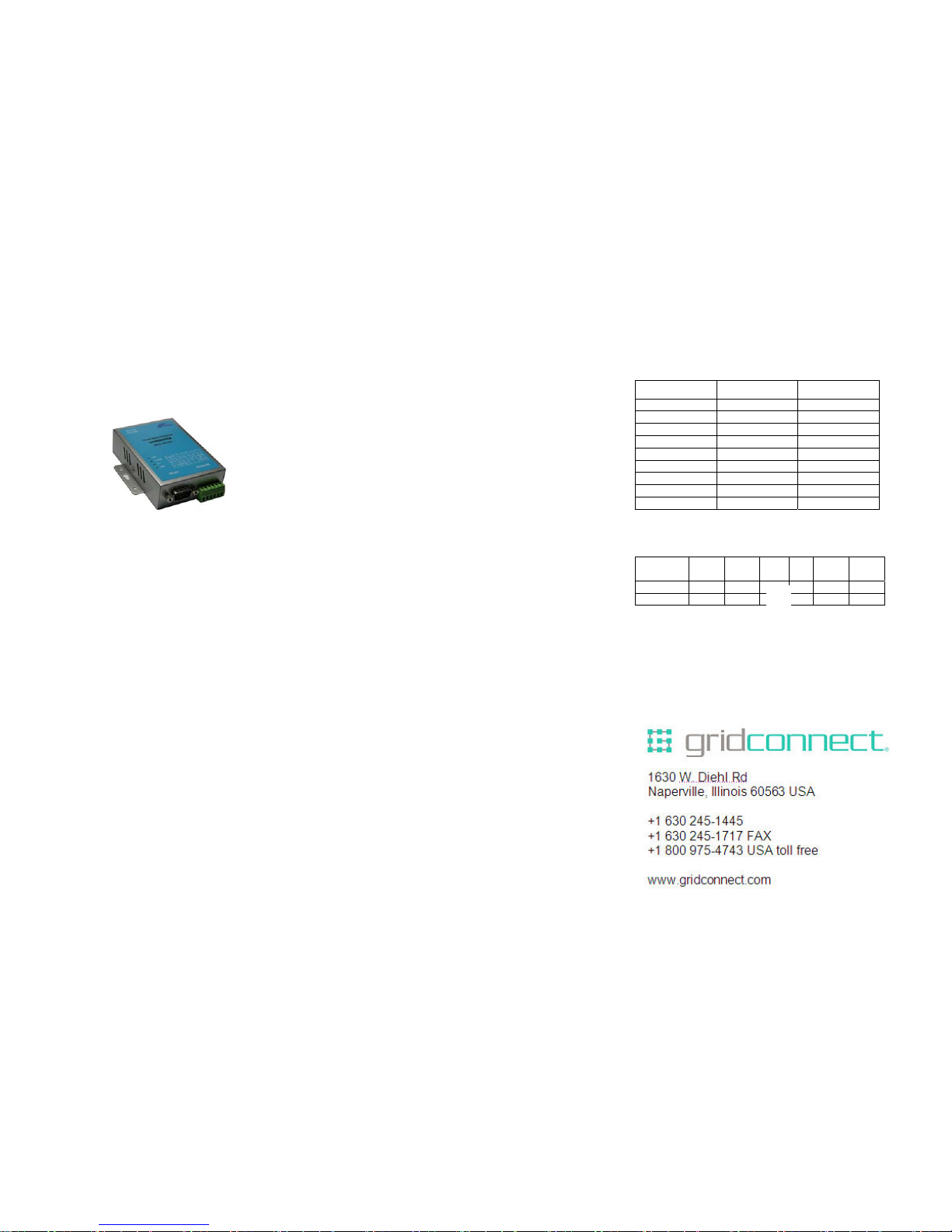
GC-ATC-2000
TCP/IP TO RS-232/422/485 CONVERTER
User’s Manual
1.1 Introduction
The GC-ATC-2000 is a RS232/RS485 to TCP/IP converter
integrated with a robust system and network management
features designed for industrial equipment to be accessed
and controlled via Intranet or Internet. By integrating RTOS
(Real Time Operating System) and complete TCP/IP protocol
stack capability, GC-ATC-2000 provides not only a robust
and high performance system to make your device
connecting to Network, but also ease installation and Internet
access.
The GC-ATC-2000 Web Configurator is a breeze to operate
and totally independent of the operating system platform you
use.
2.0 Main features
►TCP/UDP server/client support
The GC-ATC-2000 support four types of connection: TCP
server, UDP server, TCP client and UDP client, user can
select one of types to meet appl ication requirement.
►DHCP Client
DHCP (Dynamic Host Configuration Protocol) client obt ai ns
the TCP/IP configuration at start-up from a centralized DHCP
server, which means it can get IP address , an IP defa ult
gateway and DNS server.
►PPPoE Over Ethernet
PPPoE is a protocol for connecting remote hosts to the
Internet over DSL connection by simulating dial-up
connection.
►
Dynamic DNS
With dynamic DNS support, you can have a static hostname
alias for a dynamic IP address, allowing the host to be more
easily accessible from various locations on the Internet.
►Auto-negotiating 10/100Mbps Ethernet
The Ethernet interface automatically detects if it is on a 10 or
a 100 Mbps Ethernet.
►Full Network Management via Web
This feature allows you to access or manage device through
IE or Netscape on any platform. The firmware also can be
upgraded via Web browser.
►Backup and Restore configuration
This feature allows you to backup system configuration to a
file and restores it, for the security issue, the file which
backup from system is an encry ption format.
3.0
Hardware Installation & Initial Setup
3.1 RS-232 Pinout:(DB9 Male)
3.2 RS-422/485 Pinout:(six Terminal from left)
Terminal
No
1 2 3 4 5 6
RS-422 T+ T- R+ R- VIN GND
RS-485 485+ 485- - - VIN GND
(DB9Male)
Signal I/O
PIN1 DCD IN
PIN2 RXD IN
PIN3 TXD OUT
PIN4 DTR OUT
PIN5 GND PIN6 DSR IN
PIN7 RTS OUT
PIN8 RTS IN
PIN9 RI IN
1
Page 2
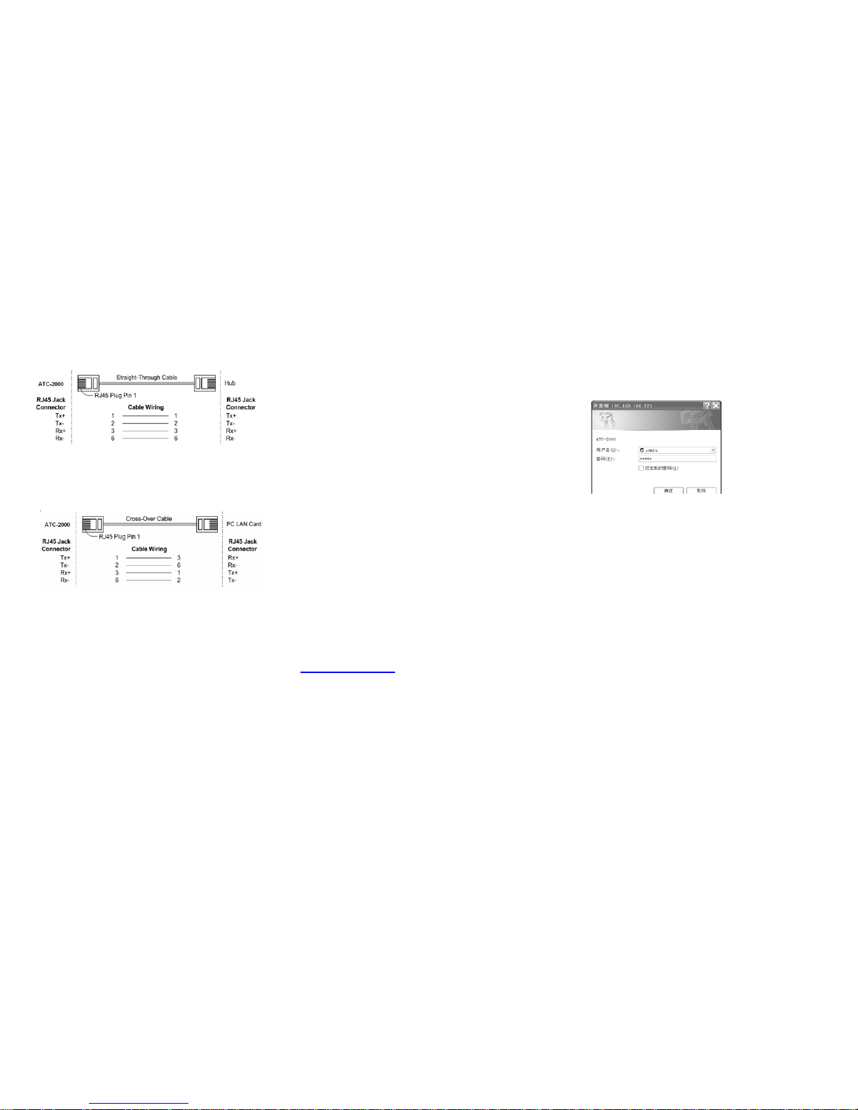
3.3 Connect to Ethernet 10/100M:
GC-ATC-2000 10/100/M Port connect to switcher or HUB use
straight-Through Cable, figure1
Figure1
GC-ATC-2000 10/100 Port t connect to Ethernet card use
cross-Through Cable, figure2
Figure2
3.4 Power Supply:
GC-ATC-2000 TCP/IP converter can adopt the product’s AC
power adapter for power supply or adopt power from ot her DC
power or device (+9 to +24V@500-100mA).
3.5 GC-ATC-2000 LED indication:
LINK Indication Ethernet Link,Green on Ethernet
Link established
10/100M Indication LINK speed, Green ON LINK
100M Ethernet
ACT Data Sending/Receiving between Serial and
the Ethernet
PWR Indication Power
4.0 Configure your GC-ATC-2000
Use this section to set up your computer to assign it a static
IP address in the 192.168.168.1 to 192.168.168.254 range
with a subnet mask of 255.255.255.0. This is necessary to
ensure that your computer can communicate with your
GC-ATC-2000. Your computer must have an Ethernet card
and TCP/IP installed. TCP/IP should already be installed on
computer using Windows 98/2000/XP and la t e r opera t in g
systems.
Step 1:Open your web browser and type
http://192.168.168.125
in the browser’s address box. This
address is the factory set IP Address of your GC-ATC-2000.
Press “Enter”.
Step 2:The “Username and Password required” prompt
box will appear. Typing “admin” (default username) in the
Username field and typing “admin” (default password) in the
Password field. Click “OK”. The setup screen will then
appear.
This chapter will show you how to configure
GC-ATC-2000 to function in your network and gain
access to your device through Intranet or Internet.
Page 3

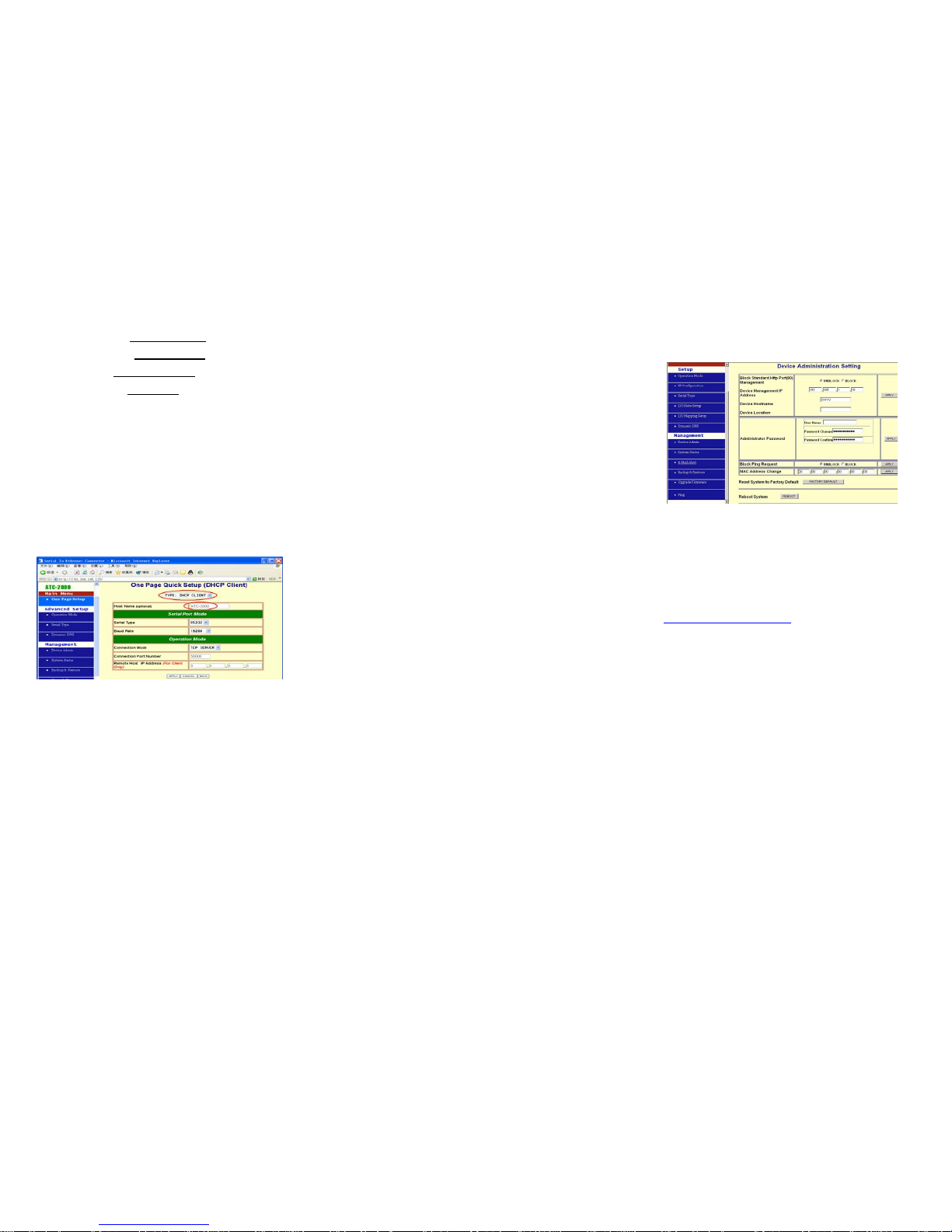
4.1 Operation mode
The GC-ATC-2000 support four operation mode: T CP
Server, TCP Client, UDP Server and UDP Client.
These modes are listed in the drop-down menu for the
Operation Mode setting. Each setup screen and
available features will differ depending on what kind of
operation mode you select. Default is TCP Server.
TCP Server
Listen Port Number: default 50000, range 0 to 65535
If your device is acted as passive to accept commands from
remote and the data be guaranteed to be received by peer is
your concern, then you can set GC-ATC-2000 as TCP Server.
Be sure the value of item Listen Port Number is same as
your remote control application using.
Close Connection When Remote Idle (second): default
300, range 0 to 32768
If you want to keep the connection between GC-ATC-2000
and your remote control application always on, then set the
value of item Close Connection When Remote Idle to 0,
otherwise, when the idle time of no any traffic on line reach
the setting value, GC-ATC-2000 will terminate this
connection.
TCP Client
Remote Connection Port Number: default 50000, range 0
to 65535
Remote Host IP Address: default 0.0.0.0
If your device is acted as active to report real-time status to
remote and the data be guaranteed to be received by peer is
your concern, then you can set GC-ATC-2000 as TCP Client.
Be sure the value of item Remote Connection Port Number
is same as your remote control application using and set the
correct value of Remote Host IP Address.
UDP Server
Listen Port Number: default 50000, range 0 to 65535
If your device is acted as passive to accept commands
from remote and the data be guaranteed to be received
by peer is not your concern, then you can set
GC-ATC-2000 as UDP Server. Be sure the value of
item Listen Port Number is same as your remote
control applicat io n us i n g.
UDP Client
Remote Connection Port Number: default 50000, range 0
to 65535
Remote Host IP Address: default 0.0.0.0
If your device is acted as active to report real-time status to
remote and the data be guaranteed to be received by peer is
not your concern, then you can set GC-ATC-2000 as TCP
Client. Be sure the value of item Remote Connection Port
Number is same as your remote control application using
and set the correct value of Remote Host IP Address.
IP Configuration
The GC-ATC-2000 support three IP connection types: Static
IP, DHCP and PPPoE. These types are li s ted in the
drop-down menu for the IP Configuration setting. Each setup
screen and available features will differ depending on what
kind of IP connection types you select. Default is Static IP
Static (or Fixed) IP
Page 4
IP Address: default 192.168.168.125
Subnet mask: default 255.255.255.0
Gateway: default 192.168.168.254
Primary DNS: default 168.95.1.1
If you are connecting through a static or fixed IP from your
network environment, perform these steps:
Step 1: Enter IP address
Step 2: Enter Subnet mask
Step 3: Enter Gateway IP address
Step 4: Enter Primary DNS IP address
Step 5: click Apply button
DHCP
Host Name (Optional): default GC-ATC, maximum
length 15 characters
If there is a DHCP Server existing in your network
environment or you subscribe a CABLE service from your ISP,
you can set IP configuration to DHCP to get a dynamic IP
address. The Host Name is an optional item, depending on
your DHCP Server setting.
Serial Type
The GC-ATC-2000 support three serial types: RS 232, RS422
and RS485, These types are listed in the drop-down menu for
the Serial Type setting. Each setup screen and available
features will differ depending on what kind of Serial Types
you select and GC-ATC-2000 product model you buy. Default
is RS232
Baud Rate: default 115200, range 1200bps to 230.4Kbps
Data Bits: 5, 6, 7, 8 (default)
Parity Check: None (default), even, odd
Stop Bits: 1 (default), 2
Flow Control: None (default), CTS/RTS (or Hardware),
XON/XOFF (or Softwa re )
Force Packet Transmit Time (ms): default 40, range 20 to
65535
The timing of transmitting an Ethernet packet, in order to get
the whole data in on packet, you can tune this setting value to
fit the data length of your device per transmission. The more
small value be set will get more less data in one packet.
RS422
The settings are similar with RS232.
RS485
RS485 Transmission Delay Time (ms): default 0, range 0 to
65535
Due to different device has different capabi li ty in handling
data received from serial port. So you can tune this setting
value to slow down the speed of GC-ATC-2000 to fit the
speed of your device handling.
Once the GC-ATC-2000 recei ve s 1 deli m it e r th r ou g h it s se ri a l
port, it immediately packs all d ata currently in its buffer and
sends it to the GC-ATC-2000’s Ethernet port.
4.1 GC-ATC-2000 Management Setup
This chapter will show you how to manage GC-ATC-2000’s
access setting as well as configure E-mail alert and firmware
upgrade.
4.2 Device Admin
Block Standard HTTP Port(80) Management: default
UNBLOCK
If for some reason, the HTTP (80) service is blocked in your
network environment and result to fail to configure or manage
GC-ATC-2000, then you select BLOCK this function with
using port 8080, instead of standard p ort 80. So you should
enter: http://192.168.168.125:8080
in your browser.
Device Management IP Address: default 192.168.1.10
In case, you forgot the GC-ATC-2000’s IP address you ever
set, this management IP can be used to connect to
GC-ATC-2000 to figure out what’s the current IP address be
used.
In case, you set GC-ATC-2000 ’s IP Configuration as DHCP
or PPPoE which will assign dynamic IP address to
GC-ATC-2000, you also can use this management IP
address to find what’s the current working IP address in
Intranet.
Note: If you forgot the IP address setting even
management IP address, please use the broadcast utility
we offer in CD to search it.
Device Hostname: default GC-ATC, maximum length 15
characters
Page 5

To describe the name of GC-ATC-2000 for manage purpose.
Device Location: no default, maximum length 15 characters
To describe the location of GC-ATC-2000 for manage
purpose.
Administrator Password
User Name: default admin
Password: default admin
To ensure the GC-ATC-2000’s security, you will be asked for
your password when you access the
GC-ATC-2000’s Web-based Utility.
User Name: Enter the user name to one of your choice.
Password: It is recommended that you change the
default password to one of your choice.
Password Confirm: Re-enter the GC-ATC-2000’s new
Password to confirm it.
Block Ping Request: default UNBOCK
To prevent hacker intruding your network, check the BLOCK
option to enable this function to reject the PING requests from
Internet.
MAC Address Change
The GC-ATC-2000’s MAC address can be changed from the
original values if necessary. Some ISPs require users to
change the MAC address to a registered one when users
change their access equipment. (Detail sees Appendix B)
Reset System to Factory Default
Click “Apply”, if you want to return all the GC-ATC-2000’s
current settings to its factory default. Note: do not restore the
factory defaults unless it is absolutely necessary.
Reboot System
Click “Apply”, if you want to clear a connection , re b oot, an d
re-initialize the unit without affecting any of your configuration
setting.
4.3 Device Status
This screen shows the GC-ATC-2000’s current status. All of
the information provided is read-only.
Product Name: the product model name of this
GC-ATC-2000.
Firmware Version: the installed version of the firmware.
System up Time: the time of system from start up to current.
Management IP Address: the current setting of
management IP.
Ethernet Status: the GC-ATC-2000’s IP Configuration , MAC
address, IP address, subnet mask, default gateway IP
address, primary DNS IP address and current connection
status.
Serial Status: the GC-ATC-2000’s setting in serial type
Statistic: the transmission and receive bytes and pa cke ts
count in Ethernet and Serial port separately.
4.4 E-Mail Alert
The GC-ATC-2000 allows you send E-Mail to alert the event
of I/O state changing. This service default is disabled.
E-mail Alert: default DISABLE
Domain Name (optional): no default, maximu m leng th 59
characters
SMTP Mail Server: no default, maximum length 27 characters
E-mail Alerts To: no default, maximum length 27 characters
Return Address: no default, maximum length 27 characters
Select ENABLE in E-mail Alert
Enter the Domain Name in this field if needed. (this is
optional)
Enter the SMTP Mail Server in the field.
Enter the e-mail accou nt you want to reach or notice in the
field of E-mail Alerts To.
Enter the e-mail account you want to return in the field of
Return Address.
4.4 Backup and Restore
This function allows you to save GC-ATC-2000’s
configuration as backup, or retrieve the configuration file you
saved before to turn the setting back.
Backup: Click “Backup” button save the current
configuration as a backup file in your hard disk.
Restore: Enter path of the configuration file you saved on
the PC. You can click “Browse” to view the folders and select
the file. Click “Restore” to retrieve it.
Note: the sub-name of file you retrieve must be “.cfg”
4.5 Upgrade Firmware
This function allows you to upgrade the latest version
firmware to keep your GC-ATC-2000 up-to-date. Befo re you
upgrade the firmware, you have to get the latest firmware and
save it on the PC you use to configur e the GC-ATC-2000.
Page 6

Browse: To select a file to upgrade, you have to enter path of
the latest firmware you saved on the PC. You can choose
“Browse” to view the folders and select the firmware.
Upgrade: After you enter or select the path, click “Upgrade”
to start the firmware upgrade process.
Note: don’t power off the router during the firmware
upgrading; otherwise the incompletion of firmware
upgrading will cause serious damage to the integrity of
the GC-ATC-2000’s firmware that will lead to fail to boot
the GC-ATC-2000 again.
4.6 Ping
This function allows you to t est the connection between
GC-ATC-2000 and LAN or between GC-ATC-2000 and
Internet.
Source IP Address: the current GC-ATC-2000’s IP address
(Read Only).
Destination IP Address: the IP Address of destination
device you want to ping.
Packet Number: the packet numbers you wish to use to ping
the destination device. The maximum numbe rs are 4.
Packet Size: the numbers of packet size you wish to use to
ping the destination device. The maximum packet sizes are
1400.
Ping Result: The result will show the numbers of sending
packet, numbers of packet receiving (Read Only).
5. Troubleshooting
PROBLEM CORRECTIVE ACTION
None of the LEDs
turn on when you
turn on the
GC-ATC-2000
Make sure that you have correct
power connected to GC-ATC-2000
and plugged in to an appropriate
power source. Check all cables
connections.
If the LEDs still do not turn on, you
may have a hardware problem. In t his
case, you should contact your local
vendor.
Can not access
GC-ATC-2000 from
Ethernet
Check cable connection between
GC-ATC-2000 and computer or hub.
Ping GC-ATC-2000 from computer.
Make sure your computer Ethernet
card is installed and functioning
properly.
Can not ping any
computer on the
LAN
If the 10/100M LED are off, check the
cable connection between
GC-ATC-2000 and your computer.
Verify that the IP address and
subnet mask of the GC-ATC-2000
and computer are in the same IP
address range.
Can not access
GC-ATC-2000 from
Serial
Check the Serial cable connection
between GC-ATC-2000 and your
device.
Verify that the GC-ATC-2000 setting
of Serial type is same as your device
and make sure the hardware jumper
is in the correction position.
 Loading...