

Page 1
CAN USB-232
User Manual
Revision E August 1, 2016
Page 2

Page 3

Copyright and Trademark
Copyright 2012-2016, Grid Connect, Inc. All rights reserved.
No part of this manual may be reproduced or transmitted in any form for any purpose other than the
purchaser's personal use, without the express written permission of Grid Connect, Inc. Grid
Connect, Inc. has made every effort to provide complete details about the product in this manual, but
makes no warranty of any kind with regard to this material, including, but not limited to, the implied
warranties of merchantability or fitness for a particular purpose. In no event shall Grid Connect, Inc.
be liable for any incidental, special, indirect, or consequential damages whatsoever included but not
limited to lost profits arising out of errors or omissions in this manual or the information contained
herein.
Grid Connect, Inc. products are not designed, intended, authorized or warranted for use as
components in systems intended for surgical implant into the body, or in other applications intended
to support or sustain life, or in any other application in which the failure of a Grid Connect, Inc.
product could create a situation where personal injury, death, or severe property or environmental
damage may occur. Grid Connect, Inc. reserves the right to discontinue or make changes to its
products at any time without notice.
Grid Connect and the Grid Connect logo, and combinations thereof are registered trademarks of Grid
Connect, Inc. All other product names, company names, logos or other designations mentioned
herein are trademarks of their respective owners.
CAN USB-232 is a trademark of Grid Connect, Inc.
Grid Connect
1630 W. Diehl Rd.
Naperville, IL 60563, USA
Phone: 630.245.1445
Technical Support
Phone: 630.245.1445
Fax: 630.245.1717
On-line: www.gridconnect.com
CAN USB-232 User Manual i
Page 4

Date
Rev.
Author
Comments
04/19/2012
A
GR
Preliminary Release
10/15/12
B
GR
Updates to drawings
11/27/12
C
GR/DQ
New Features. V01.02
05/14/2015
D
GR/DQ
16-bit Timestamp for received messages
08/01/2016
E
GR/JK
Power input specifications
Disclaimer and Revisions
Operation of this equipment in a residential area is likely to cause interference in which case the
user, at his or her own expense, will be required to take whatever measures may be required to
correct the interference.
Attention: This product has been designed to comply with the limits for a Class B digital
device pursuant to Part 15 of FCC Rules. These limits are designed to provide reasonable
protection against harmful interference in a residential installation. This equipment
generates, uses, and can radiate radio frequency energy, and if not installed and used in
accordance with this guide, may cause harmful interference to radio communications.
Changes or modifications to this device not explicitly approved by Grid Connect will void the user's
authority to operate this device.
The information in this guide may change without notice. The manufacturer assumes no
responsibility for any errors that may appear in this guide.
ii CAN USB-232 User Manual
Page 5

Warranty
Grid Connect warrants each product to be free from defects in material and workmanship for a
period of ONE YEAR after the date of shipment. During this period, if a customer is unable to
resolve a product problem with Grid Connect Technical Support, a Return Material Authorization
(RMA) will be issued. Following receipt of a RMA number, the customer shall return the product to
Grid Connect, freight prepaid. Upon verification of warranty, Grid Connect will -- at its option -repair or replace the product and return it to the customer freight prepaid. If the product is not under
warranty, the customer may have Grid Connect repair the unit on a fee basis or return it. No services
are handled at the customer's site under this warranty. This warranty is voided if the customer uses
the product in an unauthorized or improper way, or in an environment for which it was not designed.
Grid Connect warrants the media containing software and technical information to be free from
defects and warrants that the software will operate substantially for a period of 60 DAYS after the
date of shipment.
In no event will Grid Connect be responsible to the user in contract, in tort (including negligence),
strict liability or otherwise for any special, indirect, incidental or consequential damage or loss of
equipment, plant or power system, cost of capital, loss of profits or revenues, cost of replacement
power, additional expenses in the use of existing software, hardware, equipment or facilities, or
claims against the user by its employees or customers resulting from the use of the information,
recommendations, descriptions and safety notations supplied by Grid Connect. Grid Connect liability
is limited (at its election) to:
1) refund of buyer's purchase price for such affected products (without interest)
2) repair or replacement of such products, provided that the buyer follows the above procedures.
There are no understandings, agreements, representations or warranties, expressed or implied,
including warranties of merchantability or fitness for a particular purpose, other than those
specifically set out above or by any existing contract between the parties. The contents of this
document shall not become part of or modify any prior or existing agreement, commitment or
relationship.
CAN USB-232 User Manual iii
Page 6

Contents
Table of Contents
1. Overview ........................................................................................................................... 1-1
1.1 Introduction ......................................................................................................... 1-1
1.2 Hardware Description ......................................................................................... 1-3
1.3 Model Description ............................................................................................... 1-3
1.4 CAN Network ..................................................................................................... 1-4
1.5 Additional Documentation .................................................................................. 1-5
2. Getting Started ................................................................................................................. 2-6
2.1 Driver Installation ............................................................................................... 2-6
2.1.1 TeraTerm Install .................................................................................. 2-7
2.1.2 USB Drivers ........................................................................................ 2-7
2.1.3 COM Port Assignment ........................................................................ 2-8
2.1.4 USBView ............................................................................................ 2-8
2.2 Hardware Installation .......................................................................................... 2-9
2.2.1 RS232 Serial Cable ............................................................................. 2-9
2.2.2 USB Cable Wiring ............................................................................ 2-10
2.2.3 Power Options ................................................................................... 2-10
2.2.4 Item Locator CAN-232 ..................................................................... 2-11
2.2.5 Item Locator CAN-USB ................................................................... 2-11
2.2.6 Input Power ....................................................................................... 2-11
2.2.7 Isolated Power Option ....................................................................... 2-12
2.2.8 OEM Options .................................................................................... 2-12
2.2.9 Configuration Push Button ................................................................ 2-13
2.2.10 CAN Driver ..................................................................................... 2-14
2.2.11 TTL Option ..................................................................................... 2-15
2.3 Entering Configuration Mode ........................................................................... 2-16
2.3.1 RS232 Interface: ............................................................................... 2-16
2.3.2 USB Interface: ................................................................................... 2-16
2.3.3 Config Button .................................................................................... 2-17
2.4 Mode Options .................................................................................................... 2-19
2.4.1 Get Mode ........................................................................................... 2-19
2.4.2 Set Mode ........................................................................................... 2-19
2.5 COM Options .................................................................................................... 2-19
2.5.1 Get Com Port .................................................................................... 2-19
2.5.2 Set Com Port ..................................................................................... 2-20
2.6 CAN Port Options ............................................................................................. 2-20
2.6.1 Defining the CAN Bit-Time.............................................................. 2-20
2.6.2 CAN Bus State During Configuration .............................................. 2-20
2.6.3 Get CAN Port .................................................................................... 2-21
2.6.4 Set CAN Port Baud Sample Point ..................................................... 2-21
2.6.5 Set CAN Port Baud Sample Point Tolerance ................................... 2-22
2.6.6 Set CAN Port Baud Sample Point Browse ....................................... 2-22
2.6.7 Set CAN Port Baud Sample Point Tolerance .................................... 2-23
iv CAN USB-232 User Manual
Page 7

2.6.8 Set CAN Port (CLK_DIV BRG TSEG1 TSEG2 SJW) ..................... 2-23
2.7 CAN Command Mode ....................................................................................... 2-24
2.7.1 Message String Syntax ...................................................................... 2-25
2.7.2 Normal CAN Message....................................................................... 2-25
2.7.3 RTR CAN Message ........................................................................... 2-26
2.7.4 Appending CR/LF To Received Command Strings .......................... 2-26
2.7.5 Binary Formatted Messages .............................................................. 2-27
2.7.6 Get CAN Command Mode Settings .................................................. 2-29
2.7.7 Set CAN Command Mode Filter On/Off........................................... 2-29
2.7.8 Set CAN Command Mode RX Operating Mode ............................... 2-30
2.7.9 Set CAN Command Mode RX Input Format .................................... 2-30
2.7.10 Set CAN Command Mode TX Output Format ................................ 2-30
2.7.11 Set CAN Command Mode Message Output Termination ............... 2-31
2.8 CAN Virtual Command Mode .......................................................................... 2-31
2.8.1 The ‘XMIT’ and ‘RCEV’ Identifiers ................................................. 2-32
2.8.2 ‘XMIT’ Identifier .............................................................................. 2-32
2.8.3 ‘RCEV’ Identifier .............................................................................. 2-32
2.8.4 Get CAN Virtual Circuit Setting ....................................................... 2-33
2.8.5 Set CAN Virtual Circuit TX ID ......................................................... 2-34
2.8.6 Set CAN Virtual Circuit RX ID ........................................................ 2-35
2.8.7 Set CAN Virtual Circuit Forced Send Code ...................................... 2-36
2.8.8 Set CAN Virtual Circuit Forced Wake Code .................................... 2-37
2.8.9 Set CAN Virtual Circuit Timeout Send ............................................. 2-38
2.8.10 Set CAN Virtual Circuit Wake Timeout ......................................... 2-39
2.8.11 Set CAN Virtual Circuit Wait after Wakeup ................................... 2-40
2.8.12 Set CAN Virtual Circuit Wakeup Message ..................................... 2-41
2.9 Defining Filter Entries ....................................................................................... 2-42
2.10 Using Message Filters ..................................................................................... 2-42
2.10.1 How Filtering Works ....................................................................... 2-42
2.10.2 Setting Up Message Filters .............................................................. 2-43
2.10.3 Get CAN Filter ................................................................................ 2-43
2.10.4 Set CAN Filter ................................................................................. 2-44
2.10.5 Delete CAN Filter ............................................................................ 2-44
2.10.6 Delete CAN Filter Range ................................................................ 2-45
2.10.7 Delete CAN Filter All ...................................................................... 2-45
2.11 Config Entry Commands ................................................................................. 2-46
2.11.1 Get cfgcmd cm................................................................................. 2-47
2.11.2 Set cfgcmd cm enable=YES | NO ................................................... 2-47
2.11.3 Get cfgcmd vc .................................................................................. 2-47
2.11.4 set cfgcmd vc enable=YES | NO ..................................................... 2-48
2.11.5 set cfgcmd vc tbeg=timeout ............................................................. 2-48
2.11.6 set cfgcmd vc tend=timeout ............................................................. 2-48
2.11.7 set cfgcmd vc tid=timeout ............................................................... 2-48
2.11.8 set cfgcmd vc seq=”sequence” ........................................................ 2-48
2.12 CAN Timestamp Commands ........................................................................... 2-48
2.12.1 get timestamp ................................................................................... 2-49
2.12.2 set timestamp ................................................................................... 2-50
2.13 CAN Timeout Commands ............................................................................... 2-50
2.13.1 Get can timeout ................................................................................ 2-50
2.13.2 Set can timeout can_tx_busy=timeout ............................................. 2-50
2.14 Serial Number in Command Mode .................................................................. 2-51
Contents
CAN USB-232 User Manual v
Page 8

Contents
2.14.1 get sernumcmd cm .......................................................................... 2-51
2.14.2 set sernumcmd cm enable ............................................................... 2-51
2.15 Profiles ............................................................................................................ 2-52
2.15.1 Set Active Profile Number .............................................................. 2-52
2.15.2 Copy Profile .................................................................................... 2-52
2.15.3 Profile Note ..................................................................................... 2-53
2.15.4 Profile Note # .................................................................................. 2-53
2.15.5 Profile Note All ............................................................................... 2-53
2.15.6 Profile Note Text ............................................................................. 2-53
2.15.7 Profile Note #=Text ........................................................................ 2-54
2.15.8 Set Active Profile to Default ........................................................... 2-54
2.15.9 Set Specific Profile to Default ......................................................... 2-54
2.15.10 Set All Profiles to Default ............................................................. 2-54
2.16 Serial Number in Config Mode ....................................................................... 2-54
2.16.1 CAN Port SERNUM Interaction ..................................................... 2-54
2.16.2 Get Serial Number .......................................................................... 2-54
2.16.3 Get Version Number ....................................................................... 2-55
2.17 Test Options .................................................................................................... 2-55
2.17.1 Cycling LED Indicators .................................................................. 2-55
2.17.2 Generating CAN Square Wave ....................................................... 2-55
2.17.3 Test LEDs ....................................................................................... 2-55
2.17.4 Test LEDs and CAN Bus ................................................................ 2-55
2.17.5 Exit .................................................................................................. 2-55
2.18 XMODEM Download ..................................................................................... 2-56
2.19 Technical Support ........................................................................................... 2-56
vi CAN USB-232 User Manual
Page 9
Getting Started
1. Overview
1.1 Introduction
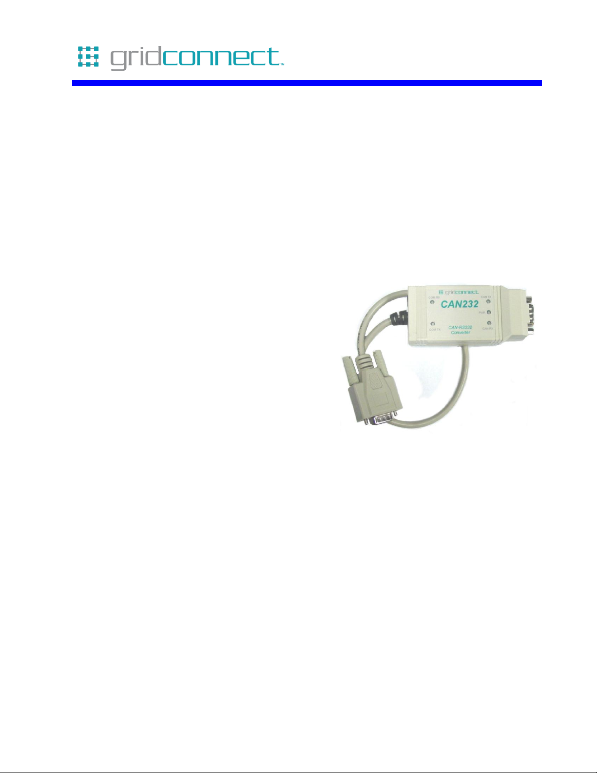
The CAN USB-232 enables the use of an RS232 or USB COM port to send and receive CAN messages on
an ISO11898 CAN network.
The CAN USB-232 can be configured to operate in either the command mode or the virtual circuit mode,
providing the user with a choice as to the type of functionality desired.
In the command mode, the CAN USB-232 is capable of sending and receiving arbitrary CAN messages
through the serial port, providing a complete CAN-232 or CAN-USB interface. This mode also supports
message filtering to limit the range of CAN identifiers that will be received.
In the virtual circuit mode, the CAN USB-232 creates a transparent ‘virtual’ link between itself and another
CAN USB-232, providing the ability for applications to use a CAN network as a point-to-point link,
supporting full-duplex exchange of arbitrary stream data.
The CAN USB-232 operating mode and all other configuration parameters are accessed through the ‘config’
button. Pressing the button causes the CAN USB-232 to enter configuration mode where it then prompts the
user to modify configuration parameters.
In addition to parameter configuration, the configuration mode also provides diagnostic tools to assist in the
measurement of bus signal propagation time and termination characteristics.
The CAN USB-232 represents an evolution of the earlier CAN-uVCCM and CAN-USB product lines,
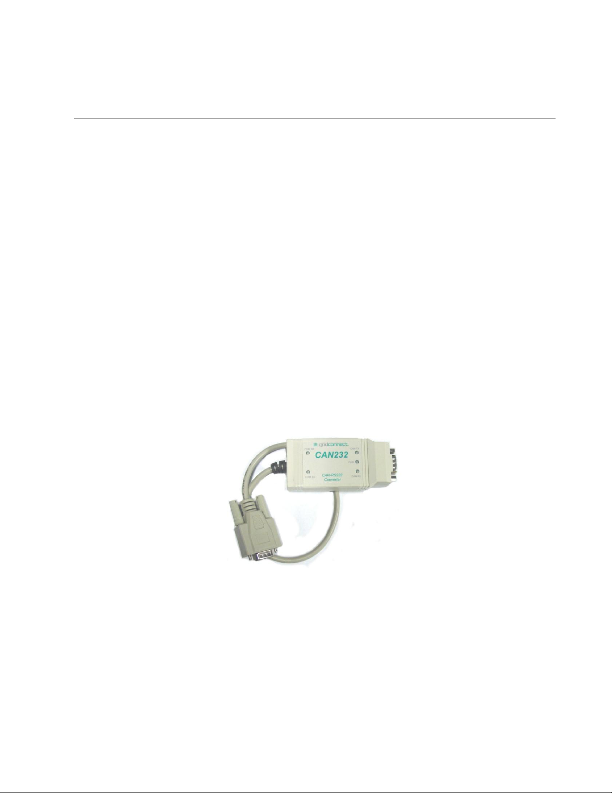
providing a performance increase and enhanced features, while retaining backward compatibility.
There are two hardware platforms, both of which execute the same firmware, with one providing a CANRS232 interface and the other a CAN-USB interface. The CAN-RS232 version is shown below.
The new units are based on an ARM Cortex-M3 32-bit microcontroller, providing 100 MIPS of processing
power with an extremely efficient instructions set. The performance increase over the legacy
microcontroller is approximately 25 times faster.
All device interfaces (UART, CAN, USB) have built-in hardware buffers that allow for high-speed data
flow without data loss. Hardware buffering, coupled with a fast and efficient CPU, allows each interface to
operate at its maximum rated limit.
CAN USB-232 User Manual 1-1
Page 10

Troubleshooting
The USB interface has been re-designed based on a parallel-port version of the current USB-to-UART
interface chip, providing 100% USB interface speed while using the same USB driver software as the earlier
CAN-USB unit. The application interface remains identical, providing 100% backward compatibility at the
USB level while adding a major performance boost.
Both versions support isolated and non-isolated CAN configurations. This option must be selected at the
time of purchase.
With the additional microcontroller FLASH memory available, the new units support a user-accessible bootloader, allowing users to download firmware updates by themselves.
By using the time-tested and very simple XMODEM protocol widely available in terminal emulation
programs, end-users can download firmware directly through the COM-RS232 or COM-USB port to update
the device.
To protect against unauthorized duplication of hardware, the firmware is encrypted with a 256-bit AES
cipher. The boot loader decrypts and verifies authenticity of the firmware to ensure only an authorized
version is being downloaded.
1-2 CAN USB-232 User Manual
Page 11
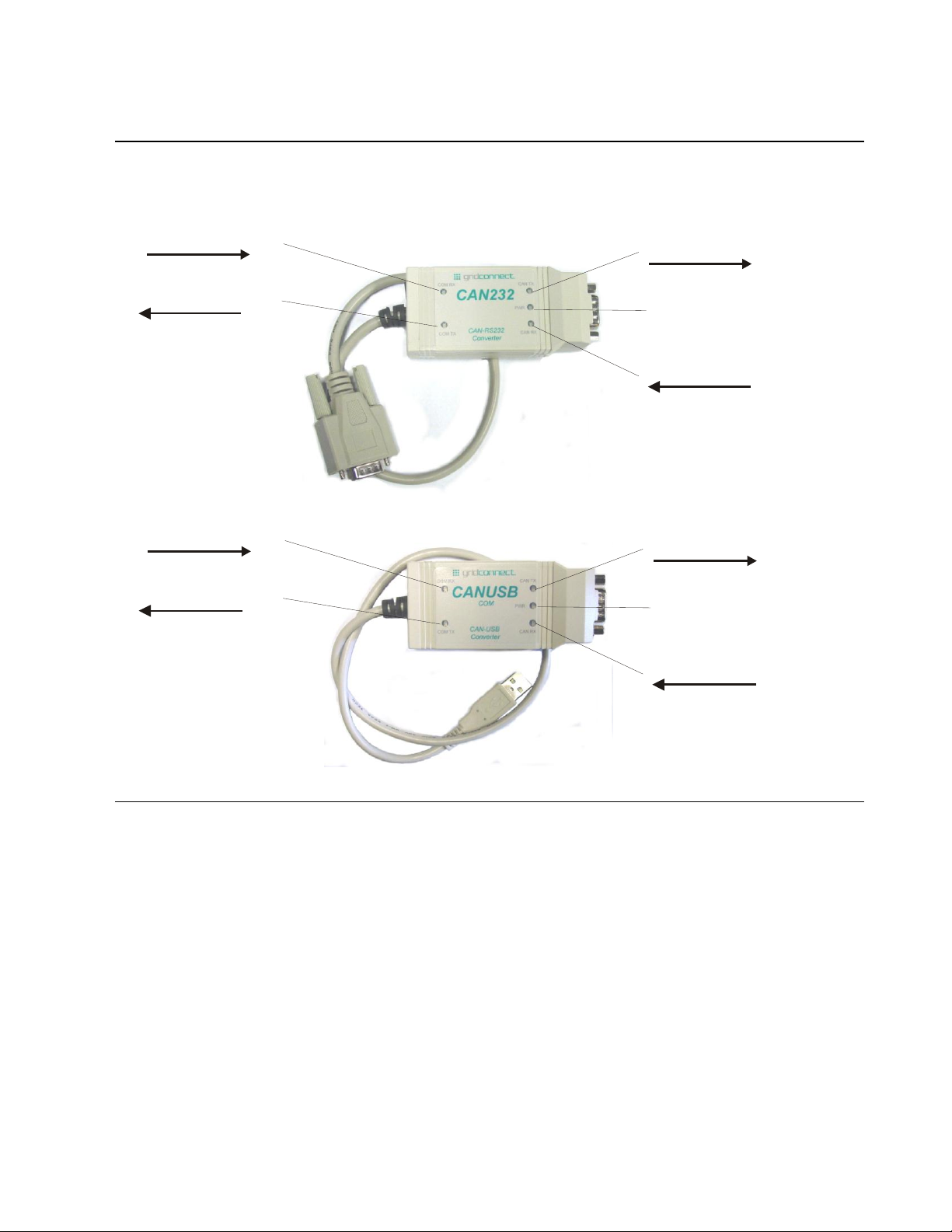
1.2 Hardware Description
COM RX Serial Receive Data
CAN TX Transmit Data
CAN RX Receive Data
COM TX Serial Transmit Data
Power
COM RX Serial Receive Data
CAN TX Transmit Data
CAN RX Receive Data
COM TX Serial Transmit Data
Power
The following drawing shows the location and function of the LEDs.
Getting Started
1.3 Model Description
There are two hardware platforms, both of which execute the same firmware, with one providing a CANRS232 interface and the other a CAN-USB interface. The CAN-RS232 platform has the option of DTE
(male) or DCE(female) on the RS232 serial cable, and the option of a Male or Female DB9 CAN connector.
CAN USB-232 User Manual 1-3
Page 12

Troubleshooting
PIN
Function
2
CAN-L
3
CAN-Ground
6
CAN-Ground
7
CAN-H
1.4 CAN Network
Before trying to send commands to the CAN USB-232, make sure the unit is attached to a valid CAN
network with at least one other node attached and running. Without another node on the network, the CAN
USB-232 will attempt to transmit the message indefinitely (as per CAN 2.0A/B specifications).
Make sure there are terminating resistors on the network. A terminating resistance of 120 ohms is
appropriate for ISO11898 drivers. Attempts to communicate over the CAN network without terminating
resistors can lead to erratic behavior and many long hours of trouble shooting.
CAN ISO11898 specifies a three wire bus: CAN_H, CAN_L, and GROUND. Failure to provide a common
ground between network nodes will create some weird behavior. At best, the system will appear to
communicate correctly until either the weather changes, you touch something, or the date changes. CAN_H
and CAN_L form a differential pair and each one must be referenced to ground in order to work properly.
1-4 CAN USB-232 User Manual
Page 13

Getting Started
Title
Description
File Name
CANUSB/232
User
Manual
This manual
in PDF
format.
CAN_USB232_UM.pdf
AN-160
COM Port
Assignment
AN_160_COMPort_Assigment_User_Guide.pdf
AN-134
Drivers for
MAC OS
AN_134_FTDI_Drivers_Installation_Guide_for_MAC_OSX.pdf
AN-104
Drivers for
Window XP
AN_104_FTDI_Drivers_Installation_Guide_for_WindowsXP(FT_000093).pdf
See Note 1.
AN-119
Drivers for
Windows 7
AN_119_FTDI_Drivers_Installation_Guide_for_Windows7.pdf
See Note 1.
Windows
CE 4.2-5.2
Installation
Guide
Windows_CE_Installation_Guide.pdf
See Note 2.
Windows
CE 6.0
Installation
Guide
Windows_CE_Installation_Guide.pdf
See Note 2.
Help Tips
Additional
Help
Information
help-tips.pdf
1.5 Additional Documentation
This manual provides basic information about the CAN USB-232 installation and operation. For specific
details about configuration and operation, please see the following manuals.
The following documents are available on the product CD.
Note 1: Includes the following versions of the Windows operating system: Windows XP, Windows Server 2003,
Windows Vista, Windows Server 2008, Windows 7, Windows Server 2008 R2.
Note 2: Includes the following versions of Windows CE 4.2-5.2 based operating systems: Windows Mobile 2003,
Windows Mobile 2003 SE, Windows Mobile 5, Windows Mobile 6, Windows Mobile 6.1 ,Windows Mobile 6.5
CAN USB-232 User Manual 1-5
Page 14
Troubleshooting
2. Getting Started
2.1 Driver Installation
Note: Install the USB drivers ONLY if you are using a CAN-USB. The files are not needed for CAN-232.
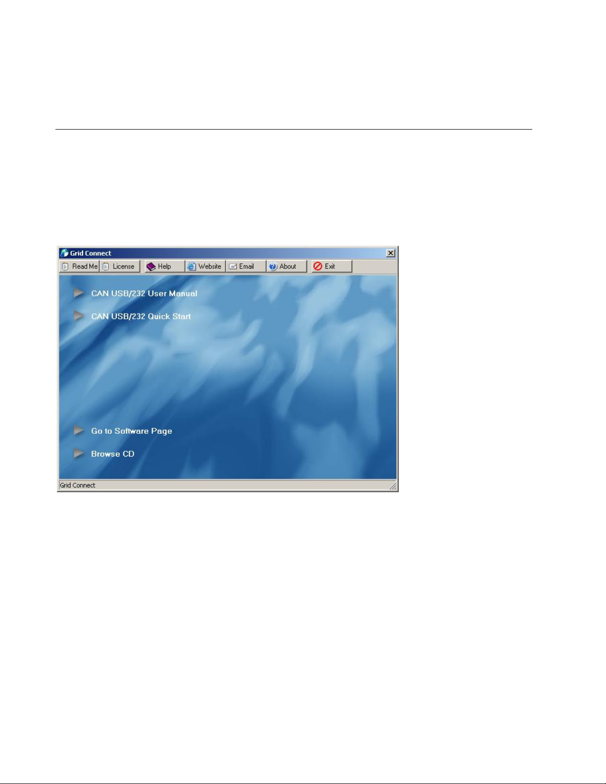
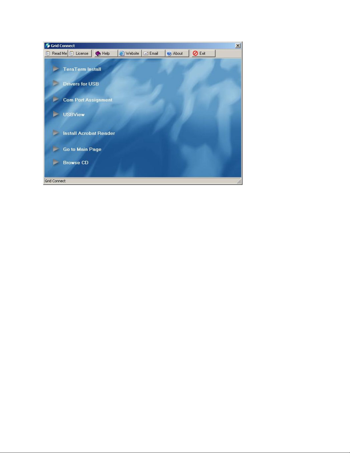
1. Insert the product CD into your CD-ROM drive. The CD will automatically start and display the main
window.
If the CD does not launch automatically:
a) Locate your CD Drive. Example: CD-RW Drive (D:)
b) Double-click on autorun.exe to start the CD browser.
Figure 1 - CD Main Window
1. Click on an item for more information.
2. Click the Browse CD button to view the contents of the CD.
3. Click the Go to Software Page button to view software options.
2-6 CAN USB-232 User Manual
Page 15
Getting Started
2.1.1 TeraTerm Install
Click this button to install TeraTerm terminal emulation software. This program is very useful for viewing
the configuration menus.
2.1.2 USB Drivers
Drivers for Linux, MAC OS and Windows can be found on individual folders on the software CD. Please
read the application note if available.
2.1.2.1 Linux
There are two files available for Linux., one in the x64 (64-bit) folder and another in the x86 (32-bit) folder.
2.1.2.2 MAC OS X
Please read the AN_134_FTDI_Drivers_Installation_Guide_for_MAC_OSX.pdf file in the Mac OS X
folder on the software CD.
2.1.2.3 Windows
The drivers for Windows includes the following versions of the Windows operating system: Windows XP,
Windows Server 2003, Windows Vista, Windows Server 2008, Windows 7, Windows Server 2008 R2.
Please read the Windows application note:
AN_104_FTDI_Drivers_Installation_Guide_for_WindowsXP(FT_000093).pdf.
Please read the Windows 7 application note:
AN_119_FTDI_Drivers_Installation_Guide_for_Windows7.pdf.
The application notes and the driver files are contained on the software CD in the Windows folder.
CAN USB-232 User Manual 2-7
Page 16

Troubleshooting
Once connected to a USB port, the CANUSB will appear as a COM port in the Device Manager. The
CANUSB will always use the lowest available COM port for operation. For instance, if COM ports 1 thru 3
are in use by other peripherals and applications, the CANUSB will use COM 4.
The CANUSB functions identically to a COM port from the reference point of both the host application and
the serial device, and it can support serial device control requests defined in the Microsoft Win32®
Communications API.
The Virtual COM Port (VCP) device drivers allow the CANUSB device to appear to the PC's application
software as an additional COM port (in addition to any existing hardware COM ports). Application software
running on the PC accesses the CANUSB device as it would access a standard hardware COM port.
However, actual data transfer between the PC and the CANUSB device is performed over the USB.
Therefore, existing COM port applications may be used to transfer data via the USB to the CANUSB-based
device without modifying the application.
2.1.2.4 Windows CE 4.2-5.2
The drivers for Windows CE includes the following versions of Windows CE 4.2-5.2 based operating
systems: Windows Mobile 2003, Windows Mobile 2003 SE, Windows Mobile 5, Windows Mobile 6,
Windows Mobile 6.1 ,Windows Mobile 6.5
Please read the application note Windows_CE_Installation_Guide.pdf. The purpose of this document is to
provide users of FTDI chips with a simple procedure for installing drivers for their devices on PDAs and
targets running Windows CE 4.2 and later. The application note and drivers files are contained on the
software CD in the Windows CE 4.2-5.2 folder.
2.1.2.5 Windows CE 6.0
Please read the application note Windows_CE_Installation_Guide.pdf. The purpose of this document is to
provide users of FTDI chips with a simple procedure for installing drivers for their devices on PDAs and
targets running Windows CE 6.0 and later. The application note and drivers files are contained on the
software CD in the Windows CE 6.0 folder.
2.1.3 COM Port Assignment
COMPort_Assignment is a utility which is used for assigning the COM Port numbers of FTDI devices. The
utility is available as a free download from the Utilities page of the FTDI website. Please read the
AN_160_COMPort_Assigment_User_Guide.pdf for installation and operating instructions. The application
note and the Reassign COMNo Utility.zip file are contained on the software CD.
2.1.4 USBView
USBView is a free utility from Microsoft that displays the USB connection tree and shows the USB devices
that are connected to it together with their configuration data. This is very useful for debugging USB
enumeration errors. USBView runs under Windows 98, ME, 2000 and XP.
2-8 CAN USB-232 User Manual
Page 17

Getting Started
J1
1
2
3
4
5
6
7
8
9
10
TX
CTS
nc
RX
nc
RTS
nc
XCFG PB
GND
+7-24 VDC
DB9-Male DTE
1
2
3
4
5
6
7
8
9
J1
1
2
3
4
5
6
7
8
9
10
TX
CTS
nc
RX
nc
RTS
nc
XCFG PB
GND
+7-24 VDC
DB9-Female DCE
1
2
3
4
5
6
7
8
9
2.2 Hardware Installation
2.2.1 RS232 Serial Cable
The following drawing shows the connection diagram for the DB-9 Male and DB-9 Female cables to the
solder pads on the circuit board at J1.
Pin 9 on the DB-9 connector is shown with +7-24 VDC going to Pin 2 of J1. This an optional method of
supplying power to the device. It is not required if you use a different power source. The factory default
configuration has no internal connection to J1-pin 2. For more details about power, see Power Options on
page 2-10.
The signal on J1-pin 9 is named XCFG PB, which is the External Configuration Push Button input. This
signal is NOT connected to the DB9-Male cable at the factory. If you need the push button input, contact the
sales department to get a quote for a custom cable.
CAN USB-232 User Manual 2-9
Page 18
Troubleshooting
USB Type A USB-232 J1
1 VBUS (Red)
2 D- (White)
3 D+ (Green)
4 GND (Black)
1 VIN
2 USBM
3 USBP
4 GND
2.2.2 USB Cable Wiring
The following drawing shows the connection diagram for the USB cable to the solder pads on the circuit
board at J1.
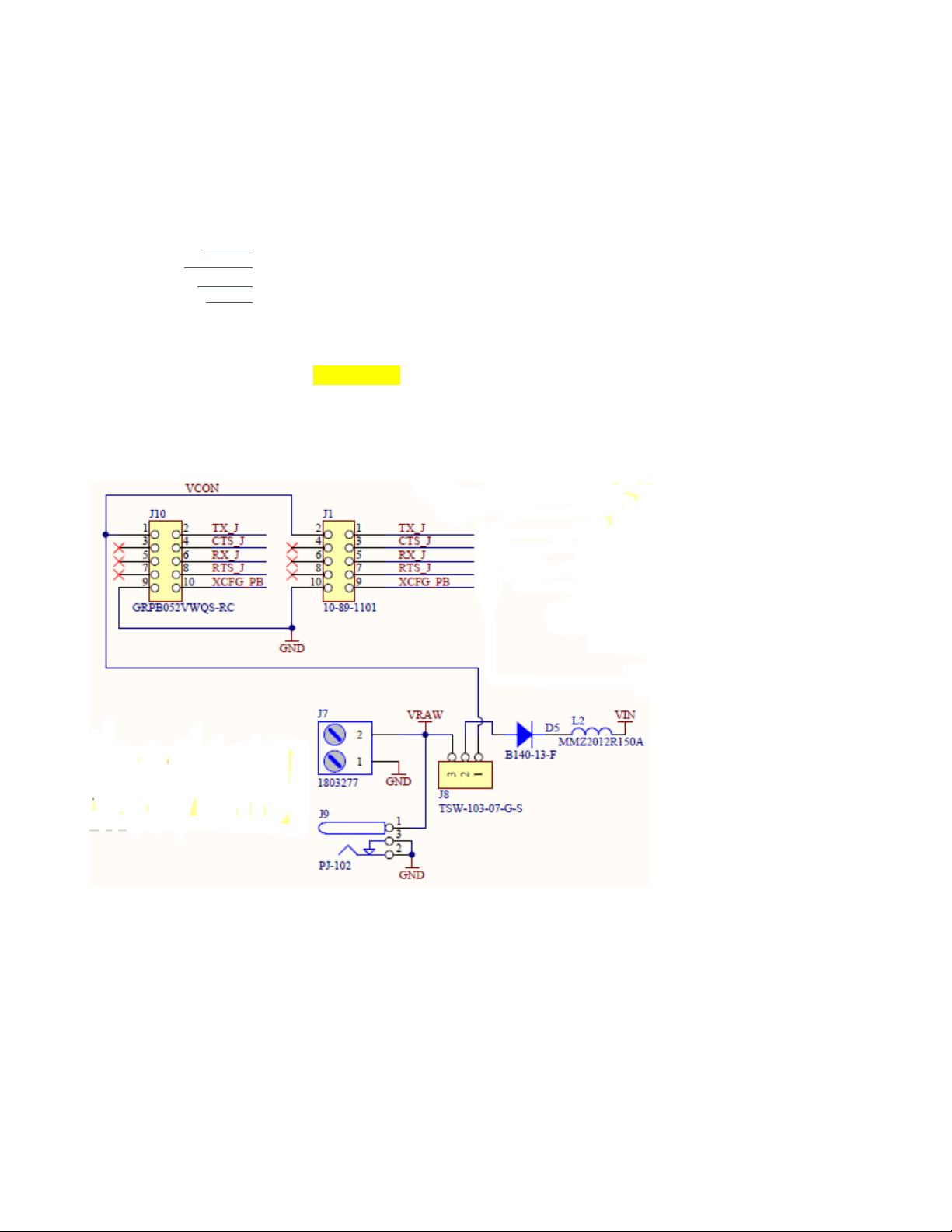
2.2.3 Power Options
For the CAN-232 model, power (+7-24 VDC) can be supplied through a Phoenix terminal block (J7),
through a barrel jack (J9), through the serial cable (usually pin 9) to J1-Pin 2, or through the OEM option
connector J10-pin 1. The factory default is the Barrel Jack J9.
The Jumper J8 should be in position 3-2 for Phoenix or barrel jack power. Jumper J8 should be in position
1-2 for serial cable or OEM (J10) supplied power. Factory default setting is a jumper in position 3-2.
2-10 CAN USB-232 User Manual
Page 19
2.2.4 Item Locator CAN-232
J4
J3
J5
J9
J1
S1
J8
J2
J6
J6
J4
J3
J2
J1
S1
J5
2.2.5 Item Locator CAN-USB
Getting Started
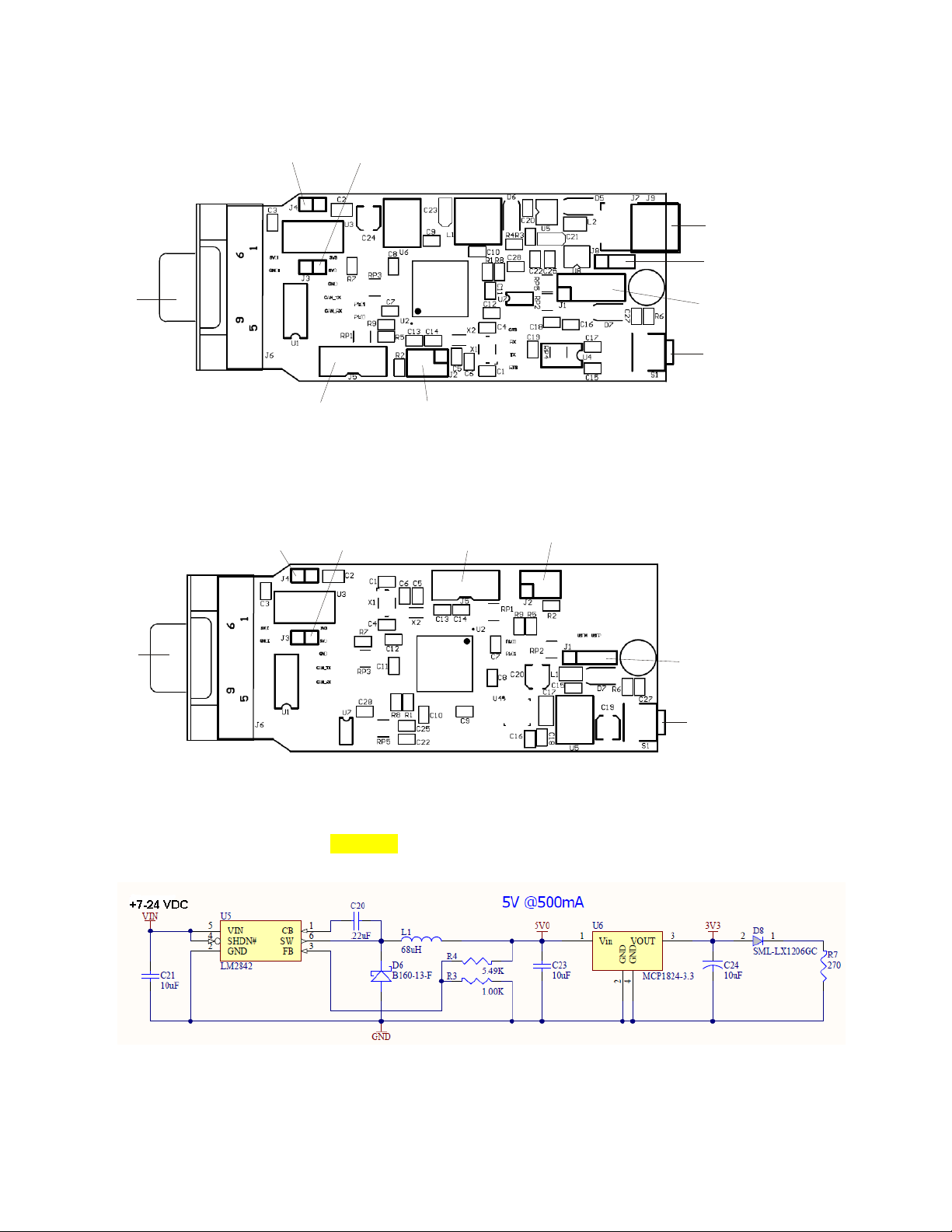
2.2.6 Input Power
The input power range is from 7-24VDC for the CAN-232 model. The 5V regulator U5 supplies power to
the U6, the 3.3V regulator. D8 is the Power LED.
CAN USB-232 User Manual 2-11
Page 20
Troubleshooting
For the CAN-USB version, power is supplied by the USB connection. D8 is the Power LED.
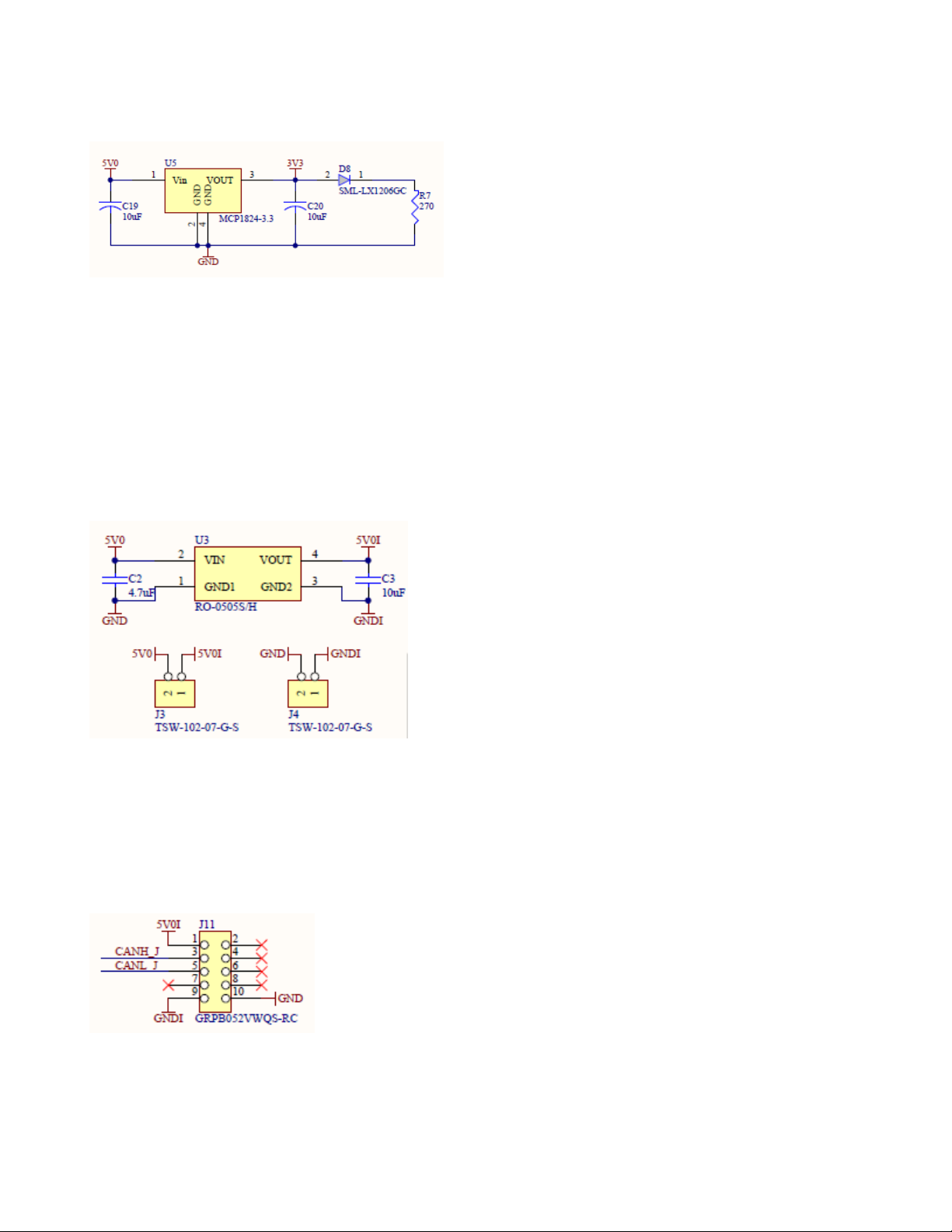
2.2.7 Isolated Power Option
Both the CAN-USB and CAN-232 can be configured for the Isolation option. Non-isolated units do not
have U3 installed. Jumpers J3 and J4 are used to supply +5 and ground to the output circuits.
For isolation, U3 is installed and jumpers J3 and J4 are removed. U3 is a DC-DC converter that isolates the
two power circuits.
The DC/DC converter is typically used in general purpose power isolation and voltage matching
applications, and feature a full industrial operating temperature range of -40°C to +85°C without derating.
The device is 2kVDC rated in a UL94V-0 package.
Note: The isolated option must be selected at the time the unit is ordered. This is not a field upgrade option.
2.2.8 OEM Options
The OEM version comes without a USB or RS232 cable. It is designed to be part of an embedded product.
Instead of a cable connector, a 10-pin header is used to connect the signals to an OEM circuit board.
The CAN signals are brought out to the OEM connector at J11. The OEM connector is a 10-pin header
soldered to the bottom side of the board.
The RS232 signals are brought out to the OEM connector at J10. Power can be supplied through pin 1 and
Ground is tied to pin 9. J8 must also be jumpered between pins 1 and 2. (See Power Options for J8)
2-12 CAN USB-232 User Manual
Page 21

The USB version is slightly different. Power is tied to pin 2 and ground to pin 10.
Getting Started
2.2.9 Configuration Push Button
Pressing the recessed push button for less than 3 seconds will put the processor into configuration mode.
Pressing the recessed push button for MORE than 3 seconds will reset the unit to factory defaults.
See the Configuration chapter for detailed operation.
CAN USB-232 User Manual 2-13
Page 22

Troubleshooting
2.2.10 CAN Driver
The ISO1050 is a galvanically isolated CAN transceiver that meets or exceeds the specifications of the ISO
11898 standard. The device has the logic input and output buffers separated by a silicon oxide (SiO2)
insulation barrier that provides galvanic isolation of up to 5000 VRMS for ISO1050DW and 2500 VRMS
for ISO1050DUB and ISO1050LDW. Used in conjunction with isolated power supplies, the device prevents
noise currents on a data bus or other circuits from entering the local ground and interfering with or
damaging sensitive circuitry.
As a CAN transceiver, the device provides differential transmit capability to the bus and differential receive
capability to a CAN controller at signaling rates up to 1 megabit per second (Mbps). Designed for operation
in especially harsh environments, the device features cross-wire, overvoltage and loss of ground protection
from –27 V to 40 V and over-temperature shut-down, as well as –12 V to 12 V common-mode range.
The ISO1050 is characterized for operation over the ambient temperature range of –55°C to 105°C.
2500-VRMS Isolation (ISO1050DUB and ISO1050LDW)
5000-VRMS Isolation (ISO1050DW)
Failsafe Outputs
Meets or Exceeds ISO 11898 requirements
Bus-Fault Protection of –27 V to 40 V
Dominant Time-Out Function
IEC 60747-5-2 (VDE 0884, Rev. 2) & IEC 61010-1 Approved
UL 1577 Double Protection Approved
IEC 60601-1 (Medical) and CSA Approved
5 KVRMS Reinforced Insulation per TUV
Approved for EN/UL/CSA 60950-1 (ISO1050DW)
Typical 25-Year Life at Rated Working Voltage
2-14 CAN USB-232 User Manual
Page 23

Getting Started
DOMINANT TIME-OUT
A dominant time-out circuit in the ISO1050 prevents the driver from blocking network communications if a
local controller fault occurs. The time-out circuit is triggered by a falling edge on TXD. If no rising edge
occurs on TXD before the time-out of the circuits expires, the driver is disabled to prevent the local node
from continuously transmitting a Dominant bit. If a rising edge occurs on TXD, commanding a Recessive
bit, the timer will be reset and the driver will be re-enabled. The time-out value is set so that normal CAN
communication will not cause the Dominant time-out circuit to expire.
FAILSAFE
If the bus-side power supply Vcc2 is lower than about 2.7V, the power shutdown circuits in the ISO1050
will disable the transceiver to prevent spurious transitions due to an unstable supply. If Vcc1 is still active
when this occurs, the receiver output will go to a failsafe HIGH value in about 6 microseconds.
THERMAL SHUTDOWN
The ISO1050 has an internal thermal shutdown circuit that turns off the driver outputs when the internal
temperature becomes too high for normal operation. This shutdown circuit prevents catastrophic failure due
to short-circuit faults on the bus lines. If the device cools sufficiently after thermal shutdown, it will
automatically re-enable, and may again rise in temperature if the bus fault is still present. Prolonged
operation with thermal shutdown conditions may affect device reliability.
BUS LOADING
In the CAN standard ISO 11898-2 the driver differential output is specified with a 60Ω load (must be
greater than 1.5V) and with a fully-loaded bus (must be greater than 1.2V). The ISO1050 is specified to
meet the 1.5V requirement with a 60Ω load, and 1.4V with a 45Ω load. The differential input resistance of
the ISO1050 is a minimum of 30KΩ. If the 167 transceivers are in parallel on a bus, this is equivalent to a
180Ω differential load. That transceiver load of 180Ω in parallel with the 60Ω (two 120Ω termination
resistors) gives a total 45Ω. Therefore, the ISO1050 supports over 167 transceivers on a single bus segment,
with margin to the 1.2V CAN requirement.
2.2.11 TTL Option
This CAN-232 model option allows a user to connect TTL level signals to the board through the serial port
cable. U4, the TTL to RS232 converter, is removed and the resistor pack, RP4 is installed. U8 is also
installed for protection. This option is by special order and NOT a field option.
CAN USB-232 User Manual 2-15
Page 24

Troubleshooting
2.3 Entering Configuration Mode
2.3.1 RS232 Interface:
To view the Configuration menu, first connect the CAN-232 serial cable to a PC running a monitor
program, such as Terra Term. Set the COM port parameters to 115200, 8, 1, None. The cable should be a
null-modem since the CAN-232 is wired as DTE.
2.3.2 USB Interface:
Use Device Manager to determine which port the CAN-USB module is assigned. Device Manager will
show the device as a USB Serial Port. To view the Configuration menu, first connect the CAN-USB cable to
a PC running a monitor program, such as Terra Term. Set the COM port parameters to 115200, 8, 1, None.
2-16 CAN USB-232 User Manual
Page 25

Getting Started
2.3.3 Config Button
Press the Config button (for less than 3 seconds) located next to the cable. The config prompt should appear
as #0#. Type help or ? to display the prompt messages.
CAN USB-232 User Manual 2-17
Page 26

Troubleshooting
Whenever the CONFIG button is pressed, the COM port settings are automatically set to 115200 N 8 1 F(for RS232 units). This ensures that an application can smoothly change from RUN to CONFIG and back to
RUN mode without needing to change COM port settings.
Note: For USB devices, the COM port settings have no effect as the actual baud rate is the full-USB speed
at all times.
To get help with a specific item, type help xx, where xx is the number in the left column next to each menu
item.
The commands are detailed in the same sequence as they appear in the following menu.
2-18 CAN USB-232 User Manual
Page 27
Getting Started
2.4 Mode Options
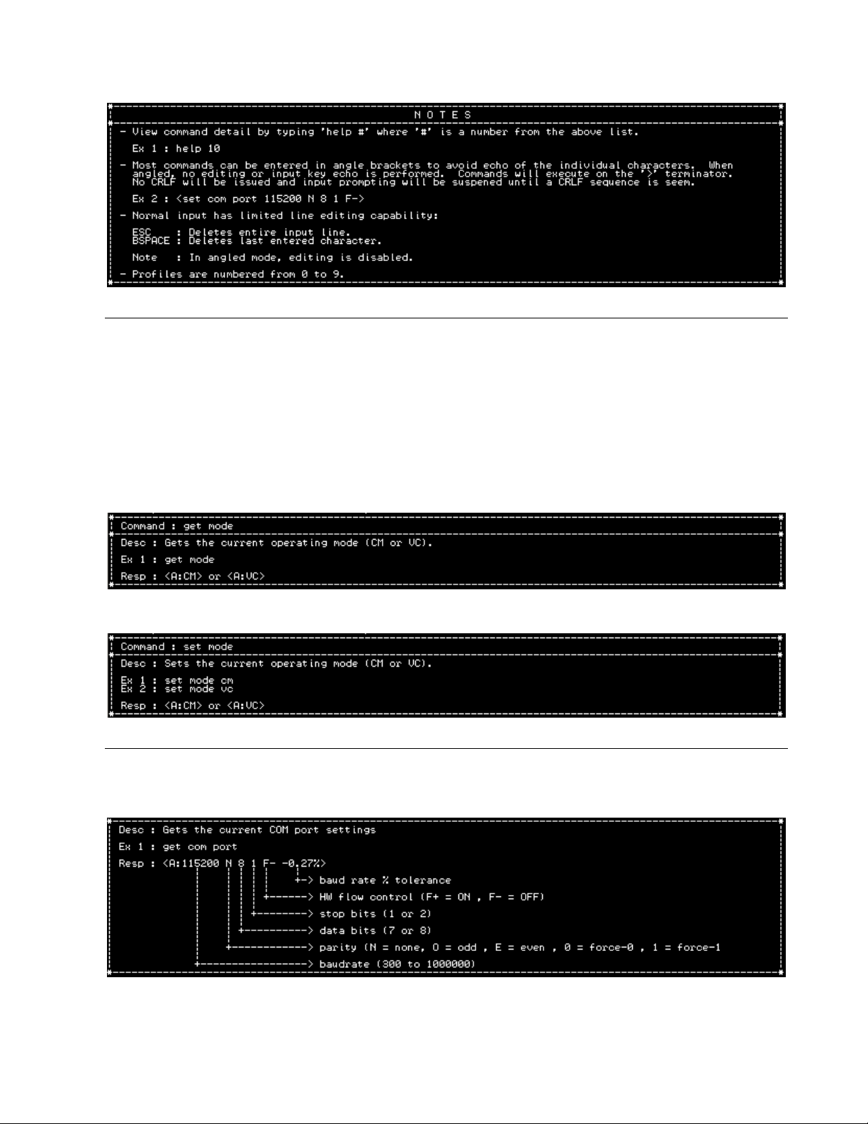
2.4.1 Get Mode
In the command mode (CM), the CAN USB-232 is capable of sending and receiving arbitrary CAN
messages via the use of ASCII formatted message strings.
In virtual circuit mode (VC), the CAN USB-232 establishes a full-duplex, virtual circuit between itself and
another CAN USB-232 or application device. By providing a virtual circuit over the CAN network,
applications can exchange data in a network-transparent fashion, using existing CAN network cabling as a
data link.
2.4.2 Set Mode
2.5 COM Options
2.5.1 Get Com Port
CAN USB-232 User Manual 2-19
Page 28
Troubleshooting
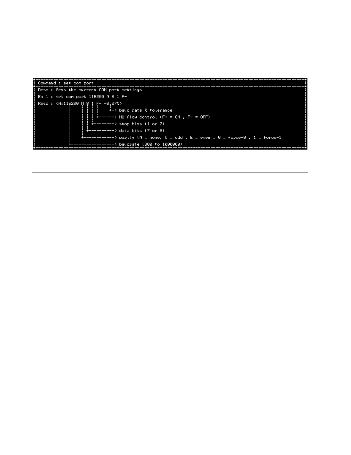
2.5.2 Set Com Port
Configuration of the COM port is simple and consists of specifying the serial baudrate, parity, the number of
data bits, stop bits, Hardware flow control. The response will echo the selected settings and the baud rate
tolerance percent.
2.6 CAN Port Options
2.6.1 Defining the CAN Bit-Time
In order for a CAN network to correctly arbitrate multiple senders and to adapt to variances in system
clocks, the low-level bit must be correctly specified for the specific characteristics of the network. The CAN
USB-232 provides a means of configuring these parameters so as to support a wide array of network
scenarios.
Note that the CAN bit rate settings can be specified as a bit-rate, sampling point, and tolerance. The code
will find the best fit solution.
2.6.2 CAN Bus State During Configuration
While the CAN USB-232 is in the configuration mode, the CAN controller is in the bus-off state. It does not
interact with the bus and is effectively ‘invisible’. Thus, it is possible to perform configuration of the CAN
USB-232 while still connected to an active CAN network and not adversely affect network operation.
Once the configuration state is exited, the CAN USB-232 will activate the CAN controller and begin
immediately interacting with the CAN network according to the CAN 2.0A/B specification.
It is the users responsibility to ensure that the configuration settings are appropriate for the network to which
the CAN USB-232 is connected so that the CAN USB-232 operates correctly and does not cause erratic
network operation.
2-20 CAN USB-232 User Manual
Page 29

2.6.3 Get CAN Port
Getting Started
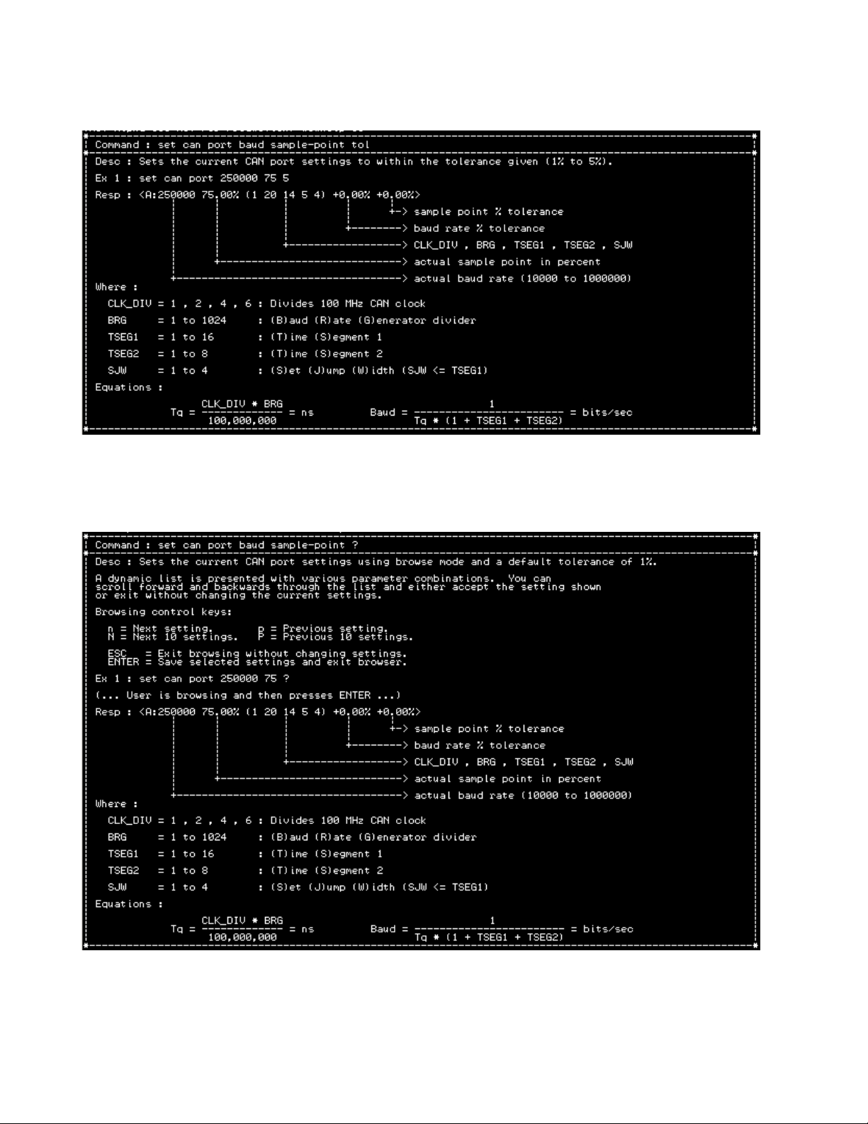
2.6.4 Set CAN Port Baud Sample Point
CAN USB-232 User Manual 2-21
Page 30
Troubleshooting
2.6.5 Set CAN Port Baud Sample Point Tolerance
2.6.6 Set CAN Port Baud Sample Point Browse
2-22 CAN USB-232 User Manual
Page 31

2.6.7 Set CAN Port Baud Sample Point Tolerance
Getting Started
2.6.8 Set CAN Port (CLK_DIV BRG TSEG1 TSEG2 SJW)
The ‘TSEG1’ parameter determines the amount of time to wait before the hardware attempts to sample the
bit. The value can range from 1 to 16.
The ‘TSEG2’ parameter determines the amount of time remaining before the end of the bit. The value can
range from 1 to 8.
CAN USB-232 User Manual 2-23
Page 32

Troubleshooting
The SJW parameter controls the maximum allowable adjustment to the sampling point. This allows for a
CAN node to adjust its sampling point when it determines that the sample point would be too early or too
late. By setting the SJW field to a large number, the CAN USB-232 can work with other nodes with a large
variation is bus oscillator tolerances. The value can range from 1 to 4.
2.7 CAN Command Mode
In the command mode, the CAN USB-232 is capable of sending and receiving arbitrary CAN messages via
the use of ASCII or Binary formatted message strings (Figure 3).
Figure 3
When the CAN USB-232 receives a valid ASCII message string, it converts it to a CAN message and
transmits it out over the CAN network.
Conversely, when a CAN message is received by the CAN USB-232, it converts it to an ASCII message
string and transmits it out of the serial port.
The CAN USB-232 supports ten (10) CAN receive message filters consisting of STD, EXT, STD-RANGE,
or EXT-RANGE. By using the masks to specify which bits of an identifier are to be compared to the filter
value, the CAN USB-232 is capable of selecting an arbitrary sub-set of the total possible CAN messages
and rejecting all others. Thus, only desired messages will be received and the total required bandwidth of the
serial link is kept to a minimum.
In order to facilitate human CAN network monitoring, there is an option to append a CR/LF sequence to
each output ASCII message string. Doing so makes it much easier to watch the incoming messages on a
terminal where each message is on a separate line. See Set CAN Command Mode Message Output
Termination on page 2-31.
2-24 CAN USB-232 User Manual
Page 33

Getting Started
2.7.1 Message String Syntax
Message strings are formatted as human-readable ASCII sequences that are easy to enter and read. Each
message string is of variable length, depending on the identifier value and the number of data bytes included
in the message.
Messages starting with ‘|’ will generate a self-receive of the transmitted message. If the message passes
filtering, it will be received as if it had been sent from some other node. Terminating with ‘!’ instead of ‘;’
issues a on-shot transmit. Ie. No attempts to automatically retry on error will happen. This is used in timetriggered CAN protocols.
Terminating with ‘!’ instead of ‘;’ issues a on-shot transmit. No attempts to automatically retry on error will
happen. This is used in time-triggered CAN protocols.
All message string characters are in upper case only. Lower case characters will be interpreted as a syntax
error and the message will be discarded.
Identifier and data fields are treated as base-16 digits (hexadecimal).
The length field is treated as a base-10 digit and must be a single digit between 0 and 8.
The syntax of both transmit and receive message strings are identical.
There are two types of message strings:
- Normal CAN messages
- Request-To-Transmit CAN messages (RTR)
As per the CAN 2.0A/B specification, RTR messages do not contain data. To support RTR messages, the
syntax is modified to include an explicit single-digit length.
2.7.2 Normal CAN Message
A normal CAN message consists of the type (11-bit or 29-bit), identifier, length, and data bytes and is
encoded as follows:
Normal CAN Message Syntax
: <S | X> <IDENTIFIER> <N> <DATA-0> <DATA-1> … <DATA-7> ;
The first character,‘:’, is for synchronization and allows the CAN USB-232 parser to detect the beginning of
a command string.
The following character is either ‘S’ for standard 11-bit, or ‘X’ for extended 29-bit identifier type.
The ‘IDENTIFIER’ field consists of from one to eight hexadecimal digits, indicating the value of the
identifier. Note that if a 29-bit value is entered and an 11-bit value was specified, the command will be
treated as invalid and ignored.
The character ‘N’ indicates that the message is a normal (non-RTR) transmission.
Each ‘DATA-n’ field is a pair of hexadecimal digits defining the data byte to be sent. If no data is to be sent
(length = zero), then the data bytes are omitted.
Each data byte specified must be a hexadecimal pair in order to eliminate ambiguity.
The terminating character ‘;’ signals the end of the message.
CAN USB-232 User Manual 2-25
Page 34

Troubleshooting
2.7.2.1 Examples
Example #1
:S123N12345678;
This message string indicates a 11-bit identifier whose value is $123, is normal, and has four data bytes: $12
$34 $56 and $78.
Example #2
:XF00DN;
This message string indicates a 29-bit identifier whose value is $F00D, is normal, and has zero data bytes.
2.7.3 RTR CAN Message
A RTR CAN message consists of the type (11-bit or 29-bit), identifier, length, does not have any data bytes,
and is encoded as follows:
RTR CAN Message Syntax
: <S | X> <IDENTIFIER> <R> <LENGTH> ;
The first character ,‘:’, is for synchronization and allows the CAN USB-232 parser to detect the beginning
of a command string.
The following character is either ‘S’ for standard 11-bit, or ‘X’ for extended 29-bit identifier type.
The ‘IDENTIFIER’ field consists of from one to eight hexadecimal digits, indicating the value of the
identifier. Note that if a 29-bit value is entered and an 11-bit value was specified, the command will be
treated as invalid and ignored.
The character ‘R’ indicates that the message is a RTR transmission.
The ‘LENGTH’ field is a single ASCII decimal character from ‘0’ to ‘8’ that specifies the length of the
message.
The terminating character ‘;’ signals the end of the message.
2.7.3.1 Examples
Example #1
:S123R8;
This message string indicates a 11-bit identifier whose value is $123, is RTR, and is of length 8.
Example #2
:XF00DR0;
This message string indicates a 29-bit identifier whose value is $F00D, is RTR, and is of length 0.
2.7.4 Appending CR/LF To Received Command Strings
When using the CAN USB-232 to view received CAN messages directly on a terminal, the user can set a
configuration parameter to append a <CR> <LF> sequence to each message string generated. This makes it
easier for the user to see each received message as each message will be on a separate line. See Set CAN
Command Mode Message Output Termination on page 2-31.
2-26 CAN USB-232 User Manual
Page 35

2.7.5 Binary Formatted Messages
The tables below show the format for Binary message format.
Getting Started
CAN USB-232 User Manual 2-27
Page 36

Troubleshooting
2-28 CAN USB-232 User Manual
Page 37

2.7.6 Get CAN Command Mode Settings
2.7.7 Set CAN Command Mode Filter On/Off
Getting Started
CAN USB-232 User Manual 2-29
Page 38

Troubleshooting
2.7.8 Set CAN Command Mode RX Operating Mode
2.7.9 Set CAN Command Mode RX Input Format
2.7.10 Set CAN Command Mode TX Output Format
2-30 CAN USB-232 User Manual
Page 39

Getting Started
2.7.11 Set CAN Command Mode Message Output Termination
2.8 CAN Virtual Command Mode
In virtual circuit mode, the CAN USB-232 establishes a full-duplex, virtual circuit between itself and
another CAN USB-232 or application device. By providing a virtual circuit over the CAN network,
applications can exchange serial stream data in a network-transparent fashion, using existing CAN network
cabling as a data link (Figure 4).
Figure 4
The CAN USB-232 takes data bytes coming into the serial port and groups them into CAN messages for
transmission. When a remote CAN USB-232 or application target receives these messages, it extracts the
data bytes and recreates the original data stream on its serial output port. This operation is fully transparent
to the connected application devices.
The virtual circuit requires two, user-configurable, CAN identifiers in order to identify the source &
destination devices for the circuit. Since virtually every CAN protocol provides a sub-set of unused or ‘user-
specific’ identifiers, establishing a virtual circuit on a CAN network in conjunction with an existing protocol
is supported and very easy to do.
The CAN USB-232 only sends CAN messages when eight bytes of data have been received. This leads to a
case where the last part of a data stream is not sent if it is less than eight bytes long. To deal with this in a
transparent fashion, the CAN USB-232 provides a timeout feature that will automatically force a
transmission of the last accumulated byte(s) after a specified maximum waiting time.
CAN USB-232 User Manual 2-31
Page 40

Troubleshooting
The CAN USB-232 can also be configured to force immediate transmission upon detection of specific userconfigured bytes in the data stream (CR or LF, for example).
It also supports defining and sending of WAKE messages to support CAN networks that go into SLEEP
mode. See more detail in help options under ‘set can vc’
2.8.1 The ‘XMIT’ and ‘RCEV’ Identifiers
When configuring the CAN USB-232 for Virtual Circuit operation, two identifiers must be specified in
order for the virtual circuit to work correctly. These two identifiers are referred to as the ‘XMIT’ and
‘RCEV’ identifiers.
2.8.2 ‘XMIT’ Identifier
The ‘XMIT’ identifier is used when the CAN USB-232 has stream data to send over the CAN network.
A CAN message is formatted to include this identifier, the number of bytes to be sent, and the actual stream
data that was received from the serial COM port. The CAN message is then sent over the CAN network.
This identifier signals that the CAN message which contains it also contains serial port stream data. Other
CAN USB-232 units can be configured to look for this identifier and will then extract the stream data from
the CAN message.
The ‘XMIT’ identifier can be either standard 11-bit or extended 29-bit.
2.8.3 ‘RCEV’ Identifier
The ‘RCEV’ identifier is used to specify which CAN message should be received by the CAN USB-232
when waiting for incoming stream data. The CAN USB-232 will discard all other messages.
When a CAN message containing this identifier is received, the data in the message is assumed to be stream
data from another CAN USB-232. This data is then read and output directly to the serial COM port of the
receiving CAN USB-232 unit, providing the completion of the virtual circuit.
If the received message for any reason contains a length of zero, or is an RTR message, it is discarded and
not stream data is generated.
The ‘RCEV’ identifier can be either standard 11-bit or extended 29-bit.
2-32 CAN USB-232 User Manual
Page 41

2.8.4 Get CAN Virtual Circuit Setting
Getting Started
CAN USB-232 User Manual 2-33
Page 42

Troubleshooting
2.8.5 Set CAN Virtual Circuit TX ID
2-34 CAN USB-232 User Manual
Page 43

2.8.6 Set CAN Virtual Circuit RX ID
Getting Started
CAN USB-232 User Manual 2-35
Page 44

Troubleshooting
2.8.7 Set CAN Virtual Circuit Forced Send Code
2-36 CAN USB-232 User Manual
Page 45

2.8.8 Set CAN Virtual Circuit Forced Wake Code
Getting Started
CAN USB-232 User Manual 2-37
Page 46

Troubleshooting
2.8.9 Set CAN Virtual Circuit Timeout Send
2-38 CAN USB-232 User Manual
Page 47

2.8.10 Set CAN Virtual Circuit Wake Timeout
Getting Started
CAN USB-232 User Manual 2-39
Page 48

Troubleshooting
2.8.11 Set CAN Virtual Circuit Wait after Wakeup
2-40 CAN USB-232 User Manual
Page 49
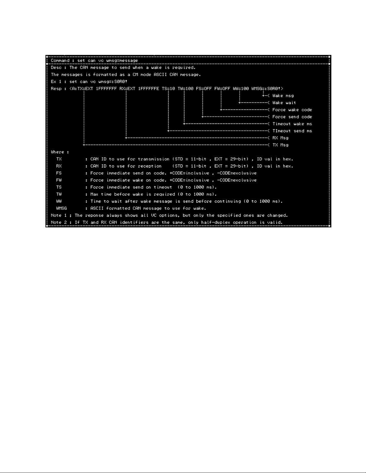
2.8.12 Set CAN Virtual Circuit Wakeup Message
Getting Started
When in VC mode and enabling force-wake and/or force-tx codes, these codes will be overridden by the
CONFIG sequence check. For example, if either of the force-wake or force-tx codes is enabled and the
CONFIG command is enabled, should the config command sequence match one of the force codes, it will
be treated as a config command character.
To avoid this, either change the force codes or change the config command sequence.
CAN USB-232 User Manual 2-41
Page 50

Troubleshooting
2.9 Defining Filter Entries
CAN messages can be filtered according to a message filter list.
The list defines which identifiers will be received and which will be ignored.
Definitions can be either a single ID or an ID range.
Standard (11-bit) and Extended (29-bit) IDs can be defined.
Definitions must not conflict nor overlap.
ID values are in hexadecimal and do not need a ‘$’ or ’0x’ prefix.
The list can be enabled or disabled.
When disabled, all CAN messages are received regardless of the definitions in the list.
When enabled, only messages which match filter definitions in the list will be passed through.
An empty filter list that is enabled will receive nothing, but still permit transmission (making the
unit effectively TX only).
Multiple filter definitions can be specified in a single command line.
The maximum number of filter definitions possible is ten (10) per profile.
EX-1: set can filter std 100 ext 200 std 1 10 ext 300 3ff
This will define four filters as follows:
11-bit : { 0x100 , 0x001 to 0x010 }
29-bit : ( 0x200 , 0x300 to 0x3FF }
All other IDs received are ignored.
2.10 Using Message Filters
In command mode, the CAN USB-232 supports message filtering through the use of identifier masks and
filter values, providing the ability to receive only a sub-set of all the possible CAN identifiers. This can
greatly reduce the required data bandwidth on a busy network by only allowing certain messages to be
received.
To use the filters, they must be enabled, their type must be specified, and appropriate ID values must be
assigned. This configuration is done while in the configuration mode.
2.10.1 How Filtering Works
Whenever the CAN USB-232 receives a CAN message from the network, it checks to see if any filters are
enabled. If none of the filters are enabled, it assumes no filtering should be performed and outputs the
ASCII message string of the message to the serial port. If any filters are enabled, the CAN USB-232 will
attempt to match the received message to each enabled filter. At the first successful match, the message is
converted to an ASCII message string and output to the serial port. If no matches were successful, the
message is discarded.
Note: The output format depends on mode : ASCII or BINARY
2-42 CAN USB-232 User Manual
Page 51

Getting Started
2.10.2 Setting Up Message Filters
To use message filtering, each filter used must be enabled and then configured as to the type of filtering that
is desired. All of these parameters are configured during the configuration process.
A filter is configured in the following order:
1) Enable the filter
2) Specify if standard or extended and if single ID or ID range.
Once all configuration parameters have been saved and the CAN USB-232 enters the normal operating
mode, the new filter settings will become active and will be applied to each received CAN message.
2.10.3 Get CAN Filter
The list can be viewed with the ‘get can filter’ command.
The list is sorted in ascending order.
Each entry is assigned an index number starting from zero.
The index number is used to identify an entry for deletion.
CAN USB-232 User Manual 2-43
Page 52

Troubleshooting
2.10.4 Set CAN Filter
Format: set can filter std id xx
| | |____ filter bits
| |
| |___ CAN ID or (id-min id-max)
|
|____ std or ext
Note: Once you set the CAN filter, make sure you set the command mode Filter to ON.
2.10.5 Delete CAN Filter
Either a single entry or and entry range can be specified.
Entries are identified by their index number.
Indexes remaining are re-sorted so there are no gaps.
EX-1: del can filter 1
2-44 CAN USB-232 User Manual
Page 53

2.10.6 Delete CAN Filter Range
Getting Started
2.10.7 Delete CAN Filter All
CAN USB-232 User Manual 2-45
Page 54

Troubleshooting
2.11 Config Entry Commands
It is now possible to enter configuration mode remotely through the COM port in either CM or VC mode.
In CM mode: ASCII mode command = :CONFIG;
BINARY mode command = FF 00 FF 02 43 4F 4E 46 49 47
Note: The last six bytes of the BINARY command are ASCII 'C' 'O' 'N' 'F' 'I' 'G'
In VC mode: 1-second idle time, followed by three '!' characters, followed by 1-second idle time.
The exact sequence can be specified by the user.
The 'set/get cfgcmd' configuration command will allow you to enable/disable the CONFIG command and
set additional parameters described below.
CM Mode:
get cfgcmd cm: Returns the current state of the CM mode config command
set cfgcmd cm enabled=yes | no: Enables or disables the command in CM mode (default is enabled)
2-46 CAN USB-232 User Manual
Page 55

Getting Started
VC Mode:
get cfgcmd vc: Returns the current state of the VC mode config command
set cfgcmd vc enabled=yes | now: Enables or disables the command in VC mode (default is disabled)
set cfgcmd vc tbeg=timeout: Minimum IDLE time to wait before matching "!!!" sequence
: 1000 to 10000 ms (default 1000)
set cfgcmd vc tend=timeout: Minimum IDLE time to wait after matching "!!!" sequence
: 1000 to 10000 ms (default 1000)
set cfgcmd vc tid=timeout: Maximum IDLE time between sequence characters
: 10 to 1000 ms (default 1000)
set cfgcmd vc seq="text": Defines the command sequence text to match
: 1 to 10 characters long (default "!!!")
Note: For the text specified in the 'seq' parameter, arbitrary ASCII values can be entered with the backslash
escape sequence followed by three decimal digits from 0 to 255.
Common escape sequences are defined:
\r : CR
\n : LF
\t : TAB
\" : " (double quote)
\\ : BACKSLASH
Ex 1 : "\000" : Binary 0x00
Ex 2 : "\r\n" " CR followed by LF
2.11.1 Get cfgcmd cm
2.11.2 Set cfgcmd cm enable=YES | NO
2.11.3 Get cfgcmd vc
CAN USB-232 User Manual 2-47
Page 56

Troubleshooting
2.11.4 set cfgcmd vc enable=YES | NO
2.11.5 set cfgcmd vc tbeg=timeout
2.11.6 set cfgcmd vc tend=timeout
2.11.7 set cfgcmd vc tid=timeout
2.11.8 set cfgcmd vc seq=”sequence”
2.12 CAN Timestamp Commands
Received CAN messages can now have a 16-bit time-stamp appended to them with a 1-ms resolution. For
backward compatibility, this feature is disabled by default and can be enabled by a configuration command.
2-48 CAN USB-232 User Manual
Page 57

Getting Started
In configuration mode:
To enable: set timestamp enable=yes
To disable: set timestamp enable=no
To determine the current state of timestamp enable: get timestamp
This will return a string with the enable status: Ex: <A:enabled=yes>
Note: commands are not case sensitive.
CAN RX Message Format Changes (when timestamping is enabled):
ASCII Mode :
In ASCII mode, the timestamp is appended to the data block in uppercase HEX ASCII in the same way that
the data field is presented (i.e.: two ASCII HEX digits to represent a byte). The '@' character is inserted
between the last DATA digit and the first TIMESTAMP digit to differentiate between the two fields.
Zero-length messages appear as they would normally, except the prefixed timestamp is added.
Ex 1:S12N12@F00F: This is a 11-bit identifier with 1 data byte and timestamp of $F00F ms.
Ex 2:X13N@2EDF: This is a 29-bit identifier with 0 data bytes and timestamp of $2EDF ms.
Ex 3:S14R5@15E5: This is a 11-bit identifier with RTR=5 and timestamp of $15E5 ms.
In short, the timestamp is always prefixed with a '@' character.
The timestamp is variable length from 1 digit to 4 digits (uppercase ASCII HEX).
BINARY Mode:
In binary mode, the received CAN messages are extended by appending the time-stamp as two binary bytes
(MSB first).
The encoding of the two byte is the same as for the DATA field (i.e., If any of the time-stamp bytes is a
synchronization character, it is escaped).
The time-stamp field is always two logical bytes, but can be expanded up to four in the case where both
MSB and LSB bytes are synchronization characters.
2.12.1 get timestamp
CAN USB-232 User Manual 2-49
Page 58

Troubleshooting
2.12.2 set timestamp
2.13 CAN Timeout Commands
It is possible, under heavy CAN bus loads or faulty CAN bus, to place the unit in a state where no more
input parsing from the COM port can occur due to the internal buffers being full and the CAN TX not being
able to proceed. Under this condition, a config command cannot be processed. This is to ensure that no
CAN messages are lost while waiting for the CAN bus to become available.
In order to prevent this, a timeout parameter can be specified that will ensure additional input parsing can
occur at the expense of some CAN messages. This will allow a CONFIG command sequence to be
recognized even when the CAN bus is overloaded or faulty.
The command to set/get the timeout follows:
get can timeout: Gets the timeout setting.
set can timeout can_tx_busy=off: Disables timeout, will wait indefinitely (default)
set can timeout can_tx_busy=1000: Sets the timeout (10 to 10000 ms)
2.13.1 Get can timeout
2.13.2 Set can timeout can_tx_busy=timeout
2-50 CAN USB-232 User Manual
Page 59

Getting Started
2.14 Serial Number in Command Mode
You can enable and configure the CAN port side to respond to CAN requests for the serial number.
2.14.1 get sernumcmd cm
Gets the current 128-bit serial number in command mode.
2.14.2 set sernumcmd cm enable
Enables or disables the command mode serial number command.
There are three identifiers that can be specified:
The RX identifier to listen for (either DATA or RTR
The TX identifier for the first 64-bits of the 128-bit serial number
The TX identifier for the second 64-bits of the 128-bits serial number
This feature can be enabled/disabled/defined from within CONFIG mode.
If enabled, it is only active when in CM mode. In VC mode, it is automatically disabled.
Operation when enabled:
Received CAN messages are compared against the RX identifier specified during configuration. If there is a
match (ID, type, RTR, etc.), then the unit will respond with two CAN messages using the two TX identifiers
defined during configuration.
The identifiers can be all the same or different, so long as they respect the rules of the CAN bus protocol.
For example, do not attempt so send two CAN identifiers with the same ID at the same time (unless at least
one of them is RTR).
This allows the end-user to query the CAN device in a system and determine its presence.
Example #1
Three units are configured to have the same RX identifier in RTR mode. Each units as unique TX
identifiers. When a node on the network issues a RX identifier request for serial numbers, the three units
will all transmit their respective serial number messages.
CAN USB-232 User Manual 2-51
Page 60

Troubleshooting
2.15 Profiles
Users can now assign short text notes to each profile to aid in remembering the settings.
The command to set/get profile notes follows:
profile note: Returns the note for the currently active profile
profile note #: Returns the note for the specified profile number (0 to 9)
profile note all: Returns a list of all profile notes.
Note : When 'all' is specified, the return format depends on whether the command was entered in EDIT or
ANGLED mode. If in edit mode, it is returned as a list with each profile note on a separate line. In angled
mode, it is returned as a single line between angle brackets.
profile note="Text": Sets the profile note for the current profile to "Text" (default "")
profile note #="Text": Sets the specified profile note to "Text" (0 to 9)
2.15.1 Set Active Profile Number
2.15.2 Copy Profile
2-52 CAN USB-232 User Manual
Page 61

2.15.3 Profile Note
profile note : Returns the note for the currently active profile
2.15.4 Profile Note #
profile note # : Returns the nore for the specified profile number (0 to 9)
2.15.5 Profile Note All
Getting Started
profile note all : Returns a list of all profile notes.
2.15.6 Profile Note Text
profile note="Text" : Sets the profile note for the current profile to "Text" (default "")
CAN USB-232 User Manual 2-53
Page 62

Troubleshooting
2.15.7 Profile Note #=Text
profile note #="Text" : Sets the specified profile note to "Text" (0 to 9)
2.15.8 Set Active Profile to Default
2.15.9 Set Specific Profile to Default
2.15.10 Set All Profiles to Default
2.16 Serial Number in Config Mode
2.16.1 CAN Port SERNUM Interaction
The SERNUM command provides a means for the user to query the CAN USB-232 for its unique 128-bit
serial number. The GET SERNUM command only works while in CONFIG mode and always returns the
serial number over the COM port.
2.16.2 Get Serial Number
2-54 CAN USB-232 User Manual
Page 63

Getting Started
2.16.3 Get Version Number
2.17 Test Options
2.17.1 Cycling LED Indicators
To confirm that all LED indicators are working, this diagnostic allows the CAN-TX/RX and COM-TX/RX
LED indicators to cycle continuously.
To terminate the diagnostic, press any key or the config button.
2.17.2 Generating CAN Square Wave
The CAN USB-232 can generate a square wave output onto the CAN bus arbitrary frequencies. It is useful
for measuring propagation delay through cabling with the aid of an oscilloscope and can be used to evaluate
bus termination.
The square wave frequency can be in the range of 10,000 to 1,000,000 Hz.
2.17.3 Test LEDs
2.17.4 Test LEDs and CAN Bus
2.17.5 Exit
CAN USB-232 User Manual 2-55
Page 64

Troubleshooting
2.18 XMODEM Download
You can do a download from XMODEM using the following steps:
1) Enter config mode
2) Type ‘get sernum’ to get the device 128-bit serial number
3) Type ‘firmware download ## ## ## ## ## ## ## ## ## ## ## ## ## ## ## ##’ where ‘##’ … is the
serial number from step 2. This must be done with care, otherwise it will not work.
At this point, there should be a prompt telling you to start the XMODEM transfer.
Do the following:
1) File menu <Alt-F>
2) Transfer <T>
3) Xmodem <X>
4) Send <S>
5) Enter the path to the IMAGE file and press enter.
You should see a progress bar indicating how the download is proceeding.
When it is done, the device will start up in CM mode (as per defaults).
To confirm operation, press the CONFIG button normally (i.e., less than three seconds) and you will be in
CONFIG mode.
2.19 Technical Support
If you are experiencing a problem, please read the user manual and other technical document supplied on
the product CD. If you are unable to solve the problem, please contact technical support.
Grid Connect technical support: (630) 245-1445.
Our phone lines are open from 8:00AM - 4:30 PM Central Time Monday through Friday excluding
holidays.
2-56 CAN USB-232 User Manual
Page 65

CAN USB-232 User Manual 2-1
 Loading...