

Page 1
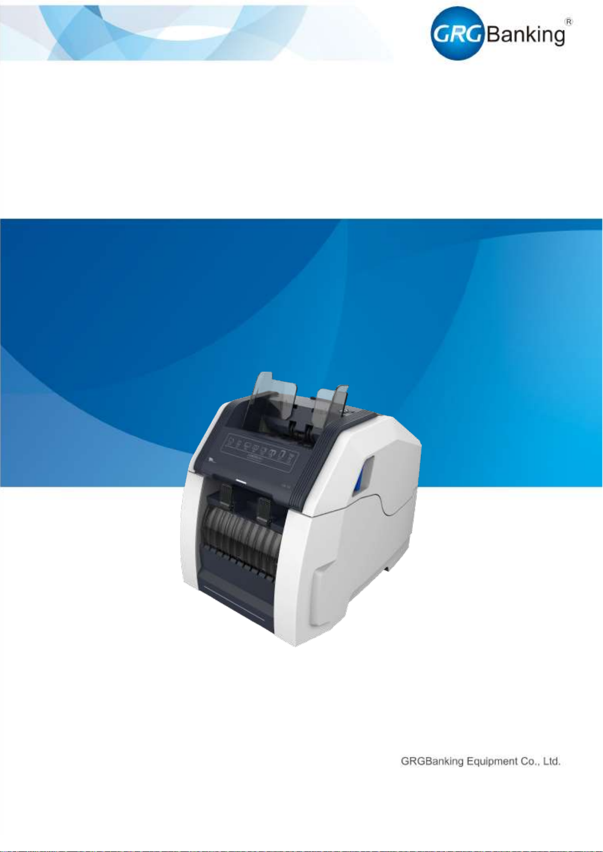
CA-10
Fast Deposit Module
User Manual
No.:
Version: V1.0
Issued on: September 2017
Page 2
Fast Deposit Module CA10 User Manual
Confidential material of GRG, No disclosure to unauthorized Party I / II
Document History
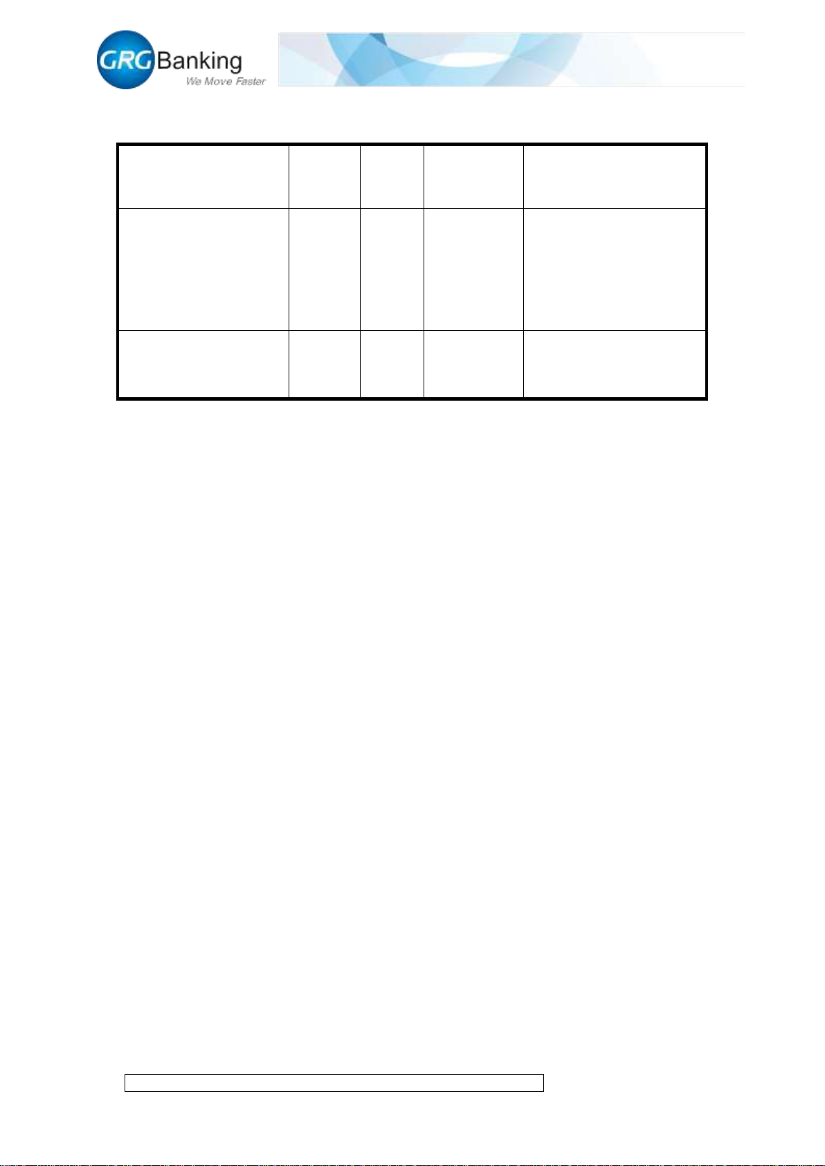
No. and name
Version
Date
Revision
description
Personnel involved
Fast Deposit Module
CA-10 User Manual
V1.0
2017.09
Created
Prepared: Dai Xiaowei,
Huang Changyan
Approved by: Wang
Yunlong, Zhang Enfu
Fast Deposit Module
CA-10 User Manual
V1.1
2018.03
Match with
new Toolplus
Prepared:Liu Peng
Approved: Zhang Enfu
Page 3
Fast Deposit Module CA10 User Manual
Confidential material of GRG, No disclosure to unauthorized Party II / II
Document History ................................................................................................................... I
Chapter 1 Overview .................................................................................................................. 1
1. Composition .............................................................................................................. 1
2. Technical parameters ................................................................................................ 2
3. Note processing procedure ........................................................................................ 2
3.1 Loading procedure ............................................................................................ 2
3.2 Pre-deposit process ............................................................................................ 3
3.3 Deposit process ................................................................................................. 3
Chapter 2 Overall Dimensions and Wiring ............................................................................... 5
1. Overall dimensions.................................................................................................... 5
2. Wiring ....................................................................................................................... 5
Chapter 3 Installation ................................................................................................................ 6
1. Installation dimensions .............................................................................................. 6
2. Maintenance space requirements .............................................................................. 6
Chapter 4 Method to Debug and Maintain CA10 with Toolplus .............................................. 8
1. Install Toolplus ......................................................................................................... 8
2. Connecting CA10 to PC ............................................................................................ 8
3. Run the Toolplus ..................................................................................................... 12
4. Upgrade main control board .................................................................................... 13
5. Upgrade DSP ........................................................................................................... 16
6. Upgrade FPGA ........................................................................................................ 18
7. View version ........................................................................................................... 20
8. Set currency type ..................................................................................................... 20
9. Set work model ....................................................................................................... 21
10. Deposit process ............................................................................................... 22
11. Get the note information ................................................................................. 26
12. Compensation image collection ...................................................................... 27
13. Reject image collection ................................................................................... 28
14. Thickness calibration ...................................................................................... 28
15. Black and white adjustment ............................................................................ 29
16. Error code query .............................................................................................. 30
Chapter 5 CA10 Thickness Adjustment Instructions ........................................................ 31
Chapter 6 CA10 Note Feeding Clearance Adjustment Instructions ................................ 35
Chapter 7 Overall Development Support ........................................................................... 37
Page 4

Fast Deposit Module CA10 User Manual
Confidential material of GRG, No disclosure to unauthorized Party 1 / 35
Chapter 1 Overview
1. Composition
As shown in Figure 1-1, the CA-10 module is divided into 10 parts depending on their
functions:
1) Input slot;
2) Note validator;
3) Thickness assembly;
4) Lower transport;
5) Diverter;
6) Reject slot;
7) Escrow slot;
8) External shutter;
9) Output slot;
10) Internal shutter
11) Pressure plate;
12) Connection port;
1
2
3
12
6
7
8
9
5
4
1011
Figure 1-1
Page 5
Fast Deposit Module CA10 User Manual
Confidential material of GRG, No disclosure to unauthorized Party 2 / 35
2. Technical parameters
Supported
currency
Support the fourth and fifth sets of all
RMB above 1 yuan (upgrade to
support multinational currencies).
Capacity of
note slots
500 notes for the input slot
(optionally 1,000 notes), 200 notes
for the escrow slot, 100 notes for the
output slot
Loading
speed
720 notes per minute
Operating
environment
0 ℃ ~ 40 ℃ 20% ~ 90% RH
(non-condensing)
Continuo
us
replenish
ment
Supported
Dimensions of
supported
envelope
Max. length 178 mm × width 90 mm
×thickness 15 mm
Slot
quantity
1 input slot, 1 output slot and 1 escrow
slot
Overall
dimensions
Length 423 mm × Width 3,40 mm ×
Height 394 mm
Power
supply
environm
ent
100-240 VAC, 50/60Hz
Weight
Net weight: 19 kg
Communi
cation
interface
LAN
3. Note processing procedure
3.1 Loading procedure
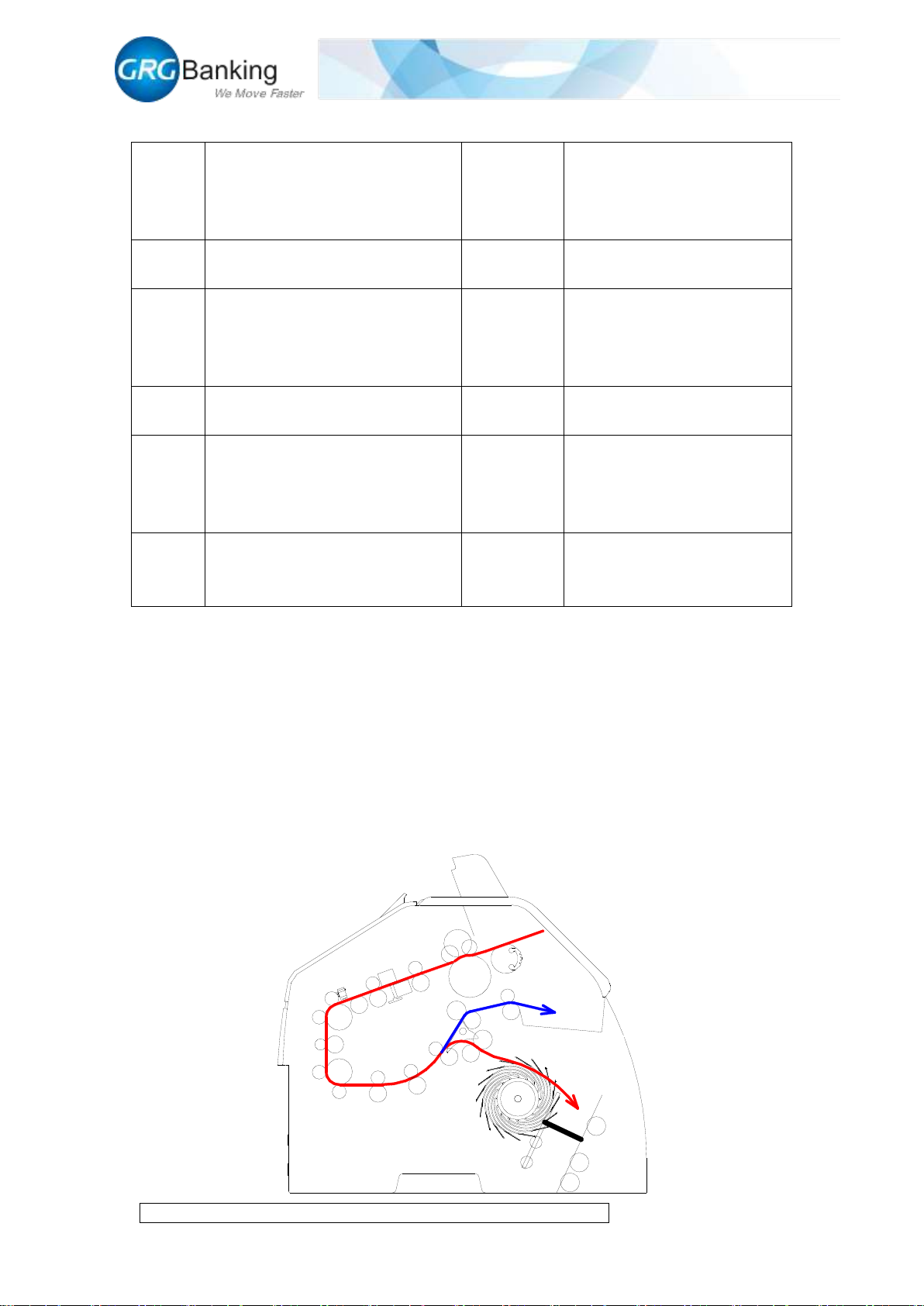
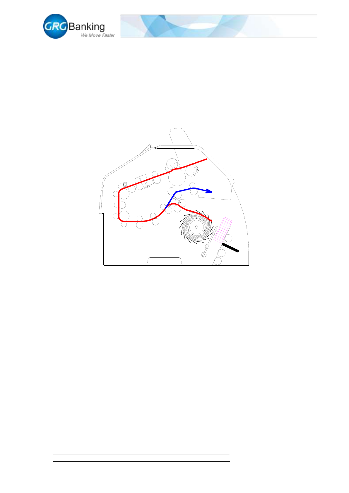
As shown by the red path in Figure 1-2, the notes fed into the note validator through feeder roller
from the input slot pass through the thickness assembly and arrive at lower transport. The notes
validated as acceptable enter into the escrow slot through the diverter as shown by the red path;
and the notes validated as unacceptable enter into the reject slot through the diverter as shown by
the blue path.
Page 6
Fast Deposit Module CA10 User Manual
Confidential material of GRG, No disclosure to unauthorized Party 3 / 35
Figure 1-2
3.2 Pre-deposit process
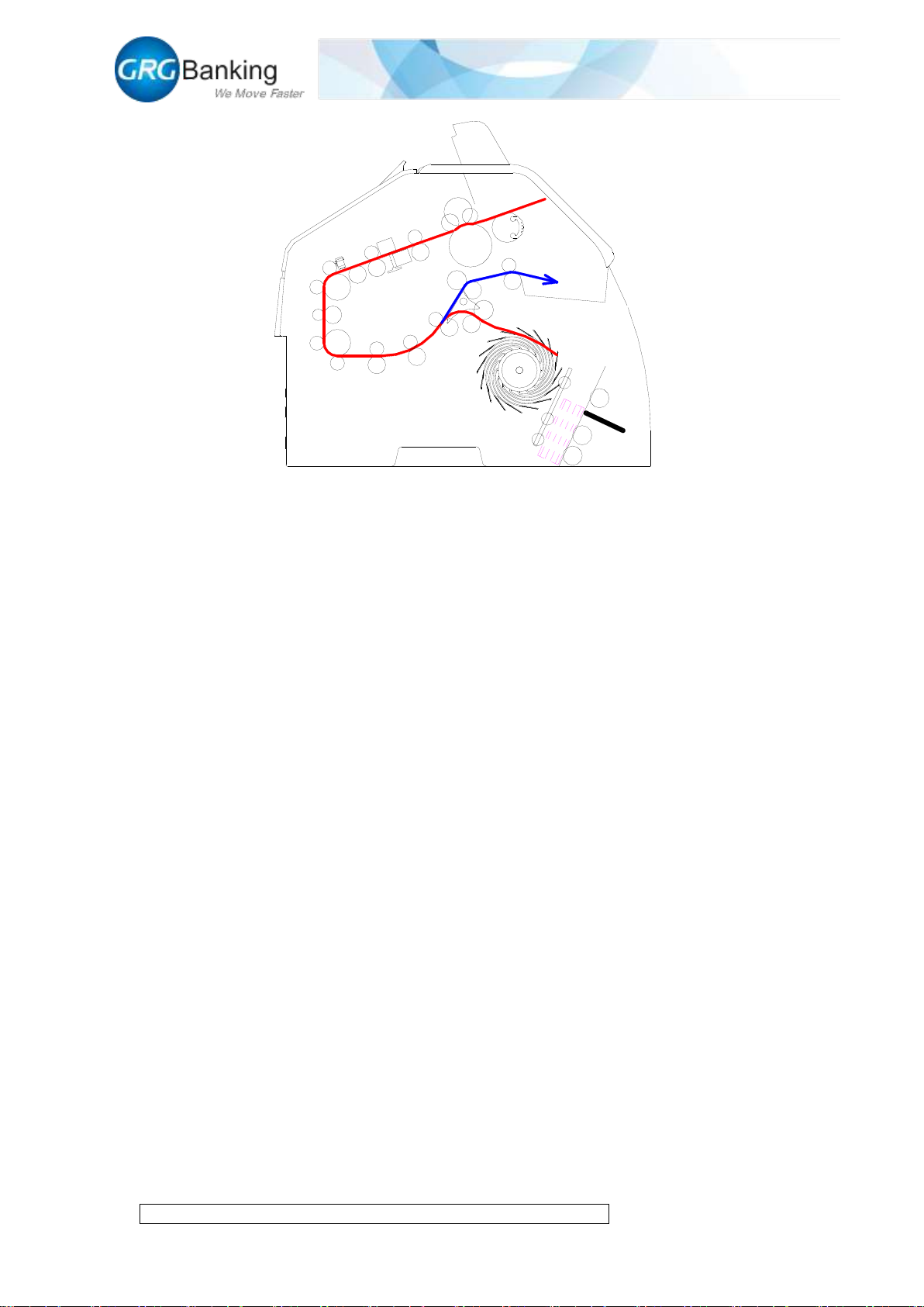
As shown in Figure 1-3, when the notes fed forward the escrow slot reach the specified quantity,
the machine stops note loading and the sensor performs the first detection. If notes are stacked
normally in the escrow slot, the internal shutter moves to the right and the pressure plate presses
the notes forward; if notes have exceptions like bursting notes or are not stacked normally in the
escrow slot, the external shutter opens automatically, and then it is required to take out the notes
from the escrow slot manually and deposit again.
Figure 1-3
3.3 Deposit process
As shown in Figure 1-4, the pressure plate presses forward the notes and the sensor performs the
second detection. If notes are stacked normally in the escrow slot, the delivery roller rotates
anticlockwise, and the notes are delivered to the output slot with the force of the delivery roller; if
notes has exception like bursting notes or are not stacked normally in the escrow slot, the internal
shutter moves to the left, and the pressure plate returns back and the external shutter opens. Then
it is required to take out the notes from the escrow slot manually and deposit again.
Page 7
Fast Deposit Module CA10 User Manual
Confidential material of GRG, No disclosure to unauthorized Party 4 / 35
Figure 1-4
Page 8
Fast Deposit Module CA10 User Manual
Confidential material of GRG, No disclosure to unauthorized Party 5 / 35
Chapter 2 Overall Dimensions and Wiring
1. Overall dimensions
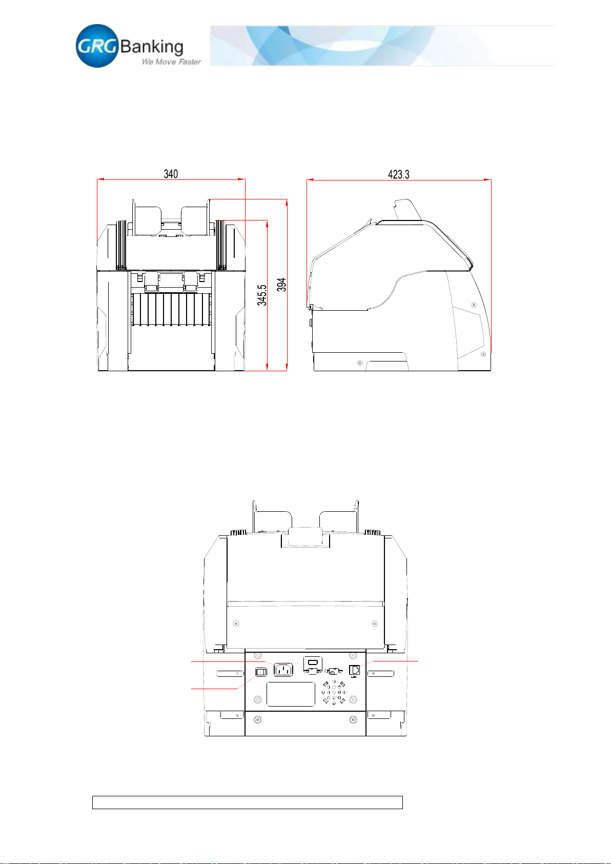
The overall dimensions are shown in Figure 2.1:
Figure 2-1
2. Wiring
As shown in Figure 2-2, the external interfaces of CA-10 module are divided into power interface
and communication interface, in which the power supply is 100-240VAC and the communication
is realized by RJ45 cable which is used to control data interaction and transmission.
Figure 2-2
Power interface
Power switch
RJ45 cable interface
Page 9
Fast Deposit Module CA10 User Manual
Confidential material of GRG, No disclosure to unauthorized Party 6 / 35
Chapter 3 Installation
1. Installation dimensions
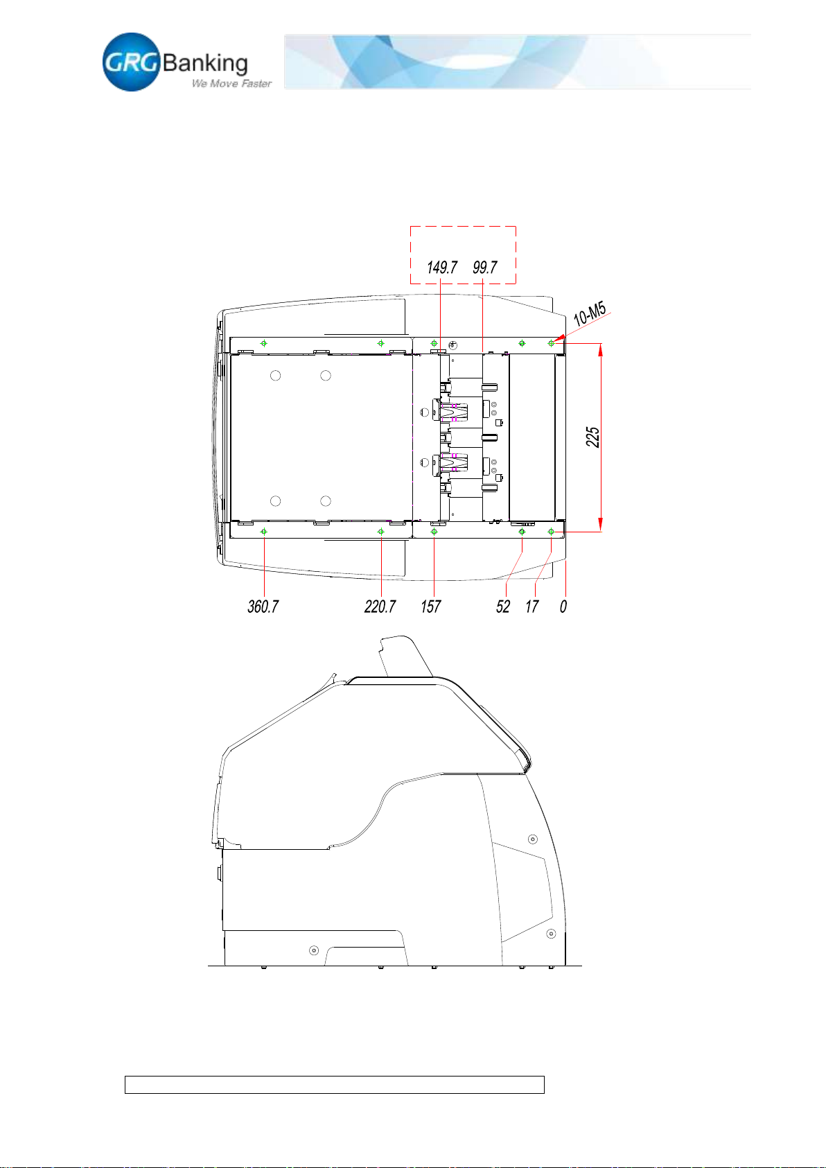
Refer to Figure 3-1 for the dimensions of mounting holes, and fix the bottom of the CA10.
Figure 3-1
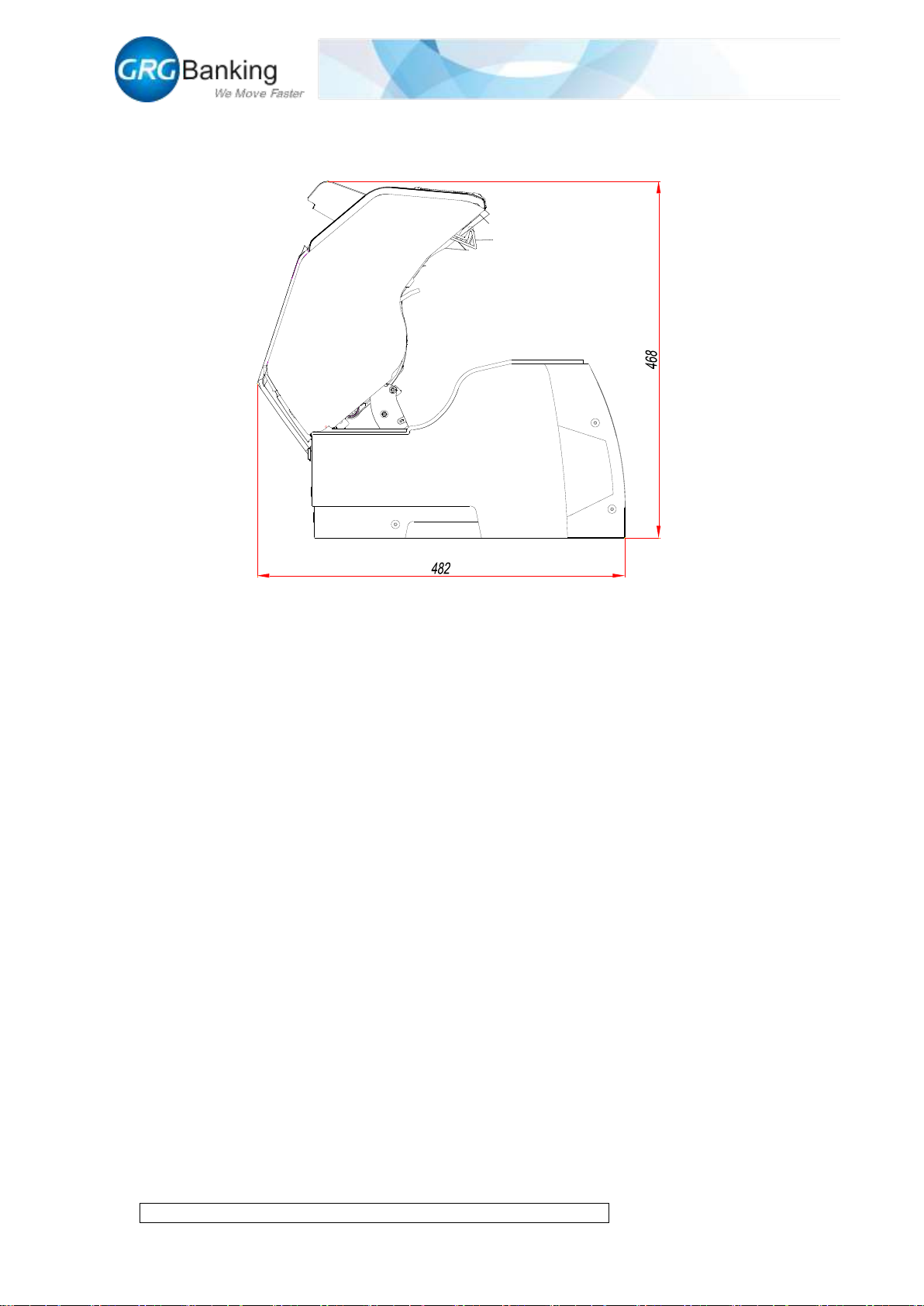
2. Maintenance space requirements
To facilitate the overall cleaning and maintenance, it is necessary to reserve enough space in
Output slot size
Page 10
Fast Deposit Module CA10 User Manual
Confidential material of GRG, No disclosure to unauthorized Party 7 / 35
advance. As shown in Figure 3-2, turn up the upper transport of CA10 to clean the space required
for maintenance.
Figure 3-2
Page 11
Fast Deposit Module CA10 User Manual
Confidential material of GRG, No disclosure to unauthorized Party 8 / 35
Chapter 4 Method to Debug and Maintain CA10 with Toolplus
1. Install Toolplus
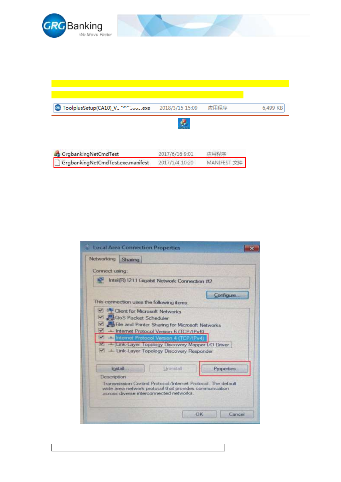
As shown in the figure below, double click “ToolplusSetup(CA10)_Vx.xxBxxxx”, Vx.xxBxxxx
means version, click “next” until finish installation, default language is English.
Double click to run the test tool “CA10_ToolPlus”, , (note: for Windows XP operating
system, it is required to remove the .manifest file under the installation directory to run the tool
normally after installation).
2. Connecting CA10 to PC
2.1 Connecting to PC with cable
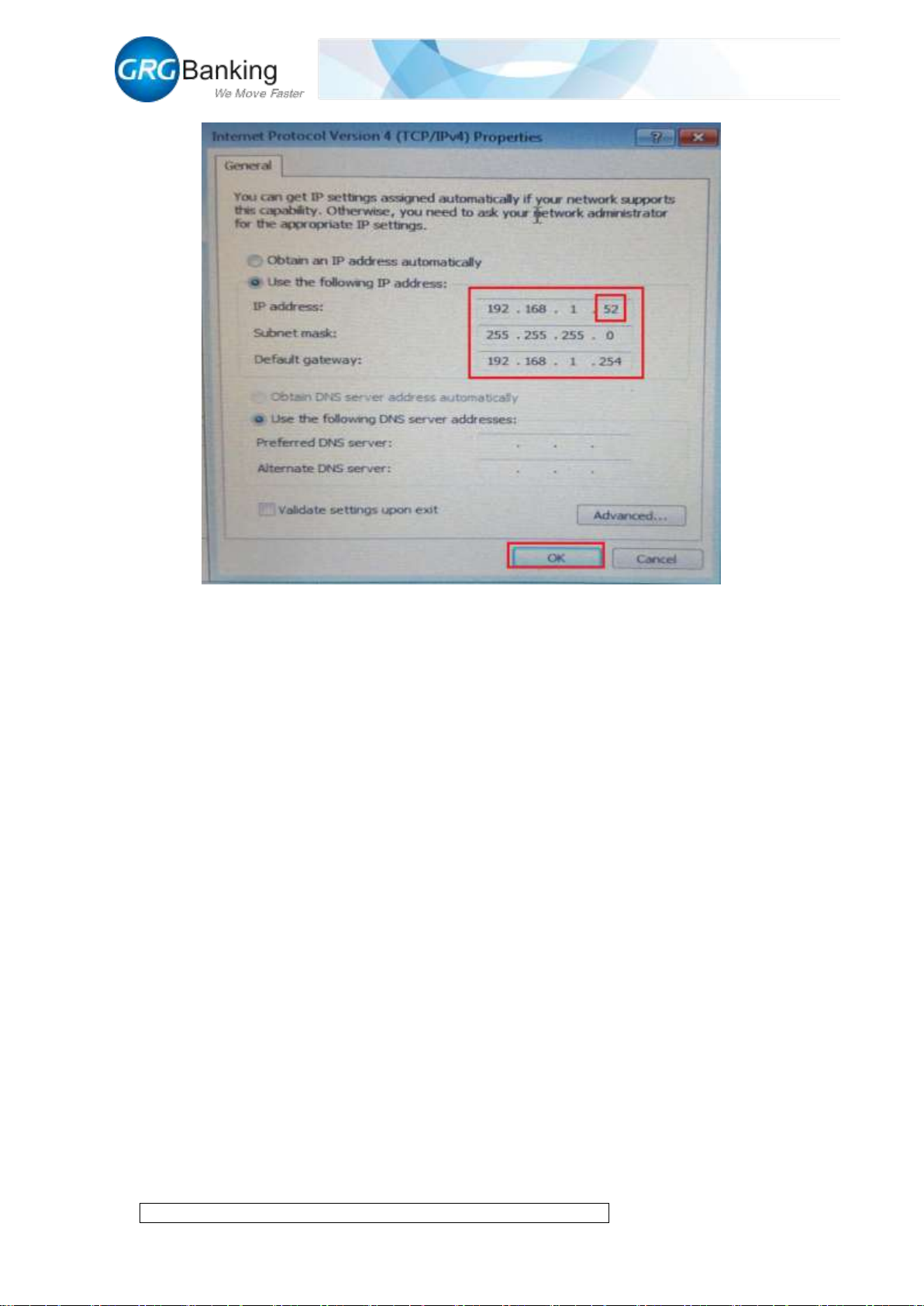
The IP address of CA10 is set by default upon the delivery from factory (IP address: 192.168.1.12,
Port: 7500).
Connect CA10 to PC with the RJ45 cable and modify the “Local Connection” IP address for PC
as shown in Figure 4-1 in which the number “52” also can be other numbers except for “12”.
Page 12
Fast Deposit Module CA10 User Manual
Confidential material of GRG, No disclosure to unauthorized Party 9 / 35
Figure 4-1
2.2 Connecting to PC by local area network
1) To connect CA10 to PC by local area network, first obtain the “Local Connection” IP address
for PC in local area network.
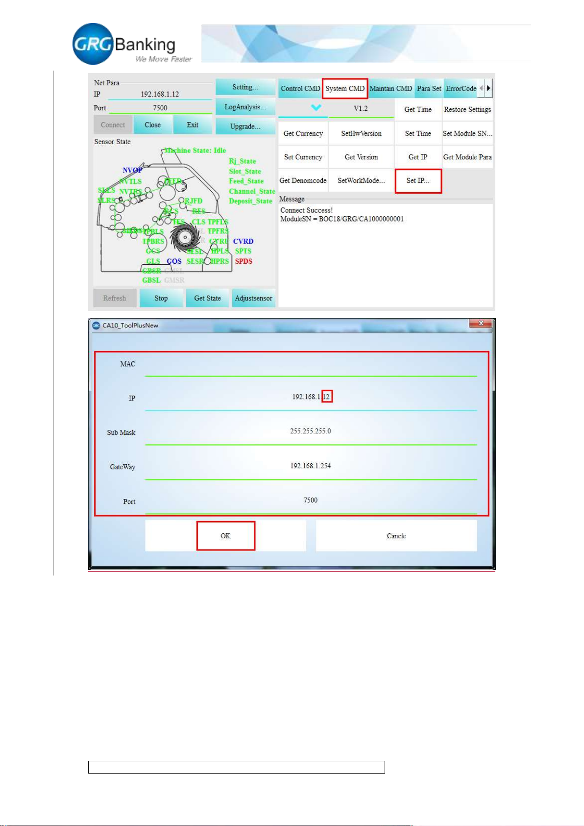
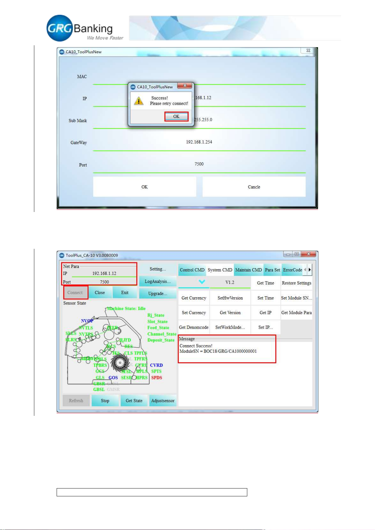
2) Using the method in 2.1 mentioned above to connect CA10 with PC, click “System CMD”
and “Set IP”, write the same IP address as that of “Local Connection” for PC in the pop-up setting
box, but the number “12” cannot be same for other PCs in the local area network, click “OK” to
display the successful interface and click “OK” again.
Page 13
Fast Deposit Module CA10 User Manual
Confidential material of GRG, No disclosure to unauthorized Party 10 / 35
Page 14
Fast Deposit Module CA10 User Manual
Confidential material of GRG, No disclosure to unauthorized Party 11 / 35
3) It is same to recover the IP address of local connection and local area network for PC.
Operate “CA10_ToolPlus” again, write the same IP address and port in step 2 and click the
“Connect” button for a successful connection.
2.3 Recovery of default IP address
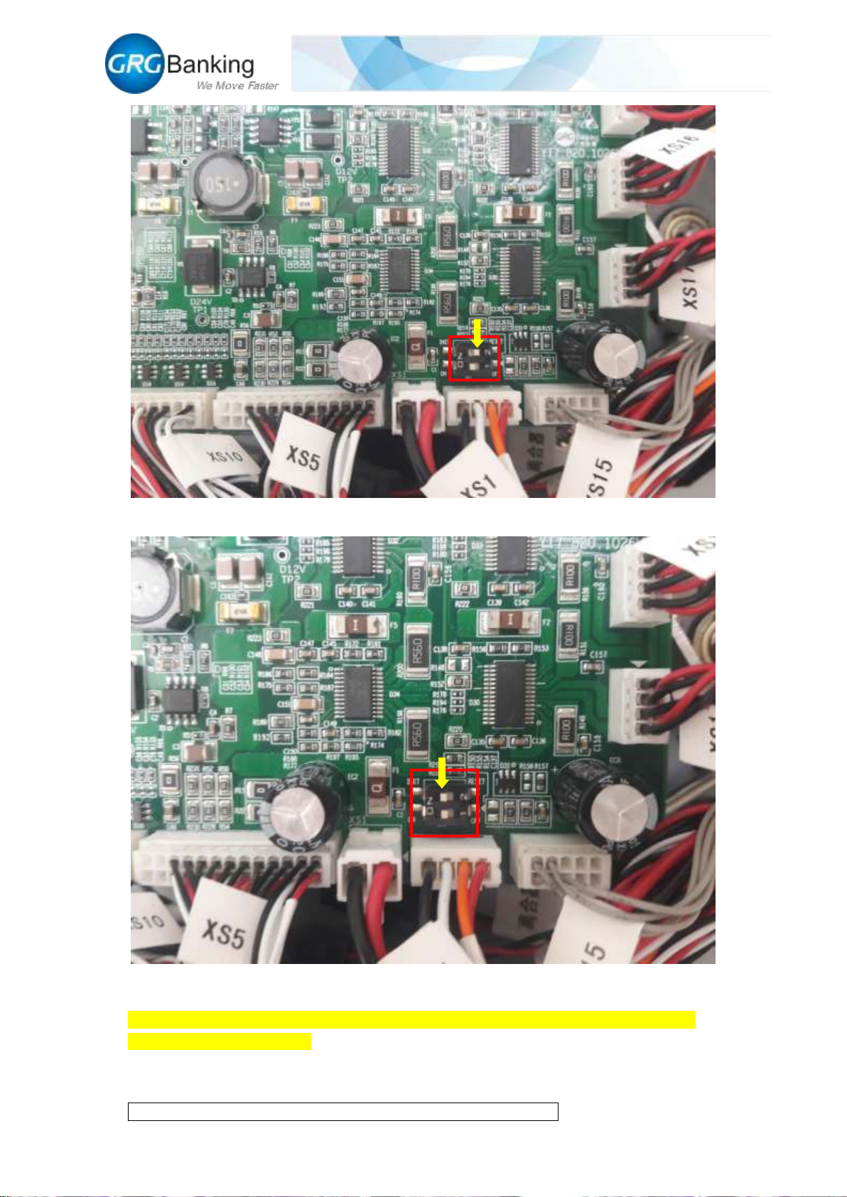
To recover the default IP address of CA 10 upon the delivery from factory, turn “pin 2” of the dial
switch to “OFF” position on the main control board, and turn it to the “ON” position after hearing
the “beep” three times to finish the reset of IP address.
Page 15
Fast Deposit Module CA10 User Manual
Confidential material of GRG, No disclosure to unauthorized Party 12 / 35
3. Run the Toolplus
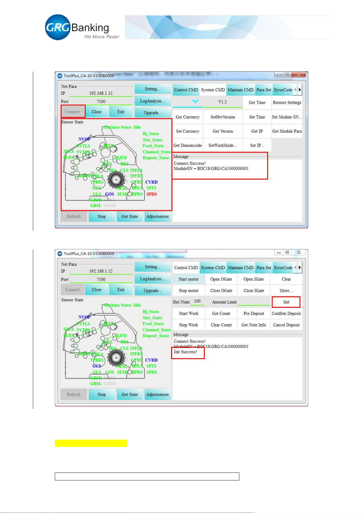
Power on CA10, after hearing three “beep” sound,then click the “Connect” button , CA10 will
connect with PC automatically (If there is no the “beep”, click the “Connect” button about 15
seconds later after powering on CA10); display “ModuleSN=BOC17/GRG/CA1000000001” in
the “Message” area for a successful connection. Otherwise, display the error information in the
Page 16
Fast Deposit Module CA10 User Manual
Confidential material of GRG, No disclosure to unauthorized Party 13 / 35
“Message” area and continue the operation below after the error information is excluded; check
the sensor states which should be same as the area of “Sensor State” in the following figure to
show the sensors working normally.
Click the “Init” button to initialize CA10 successfully and display “Success” in the “Massage”
area.
4. Upgrade main control board
4.1 Online download
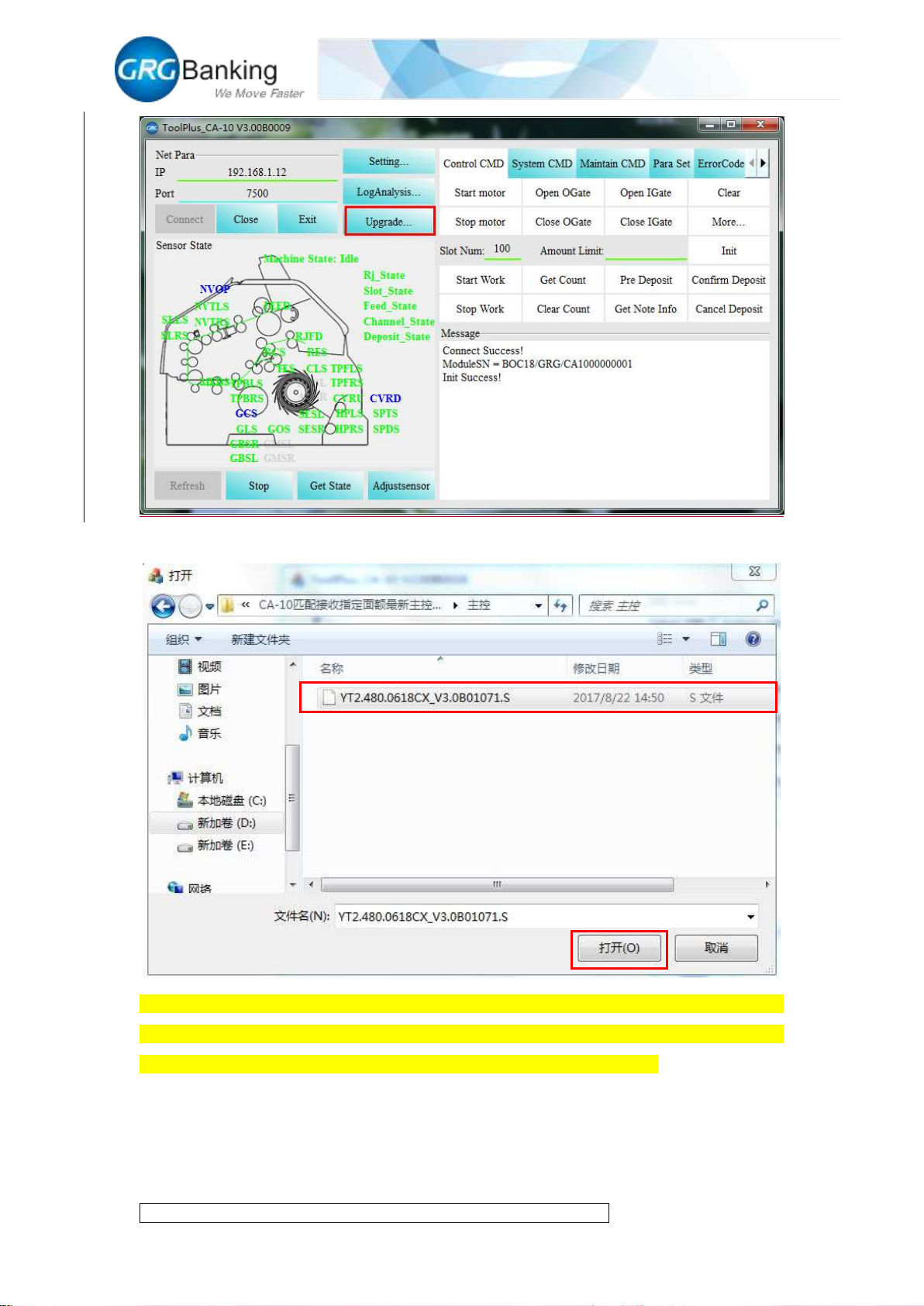
Click the “Upgrade” button;
Page 17
Fast Deposit Module CA10 User Manual
Confidential material of GRG, No disclosure to unauthorized Party 14 / 35
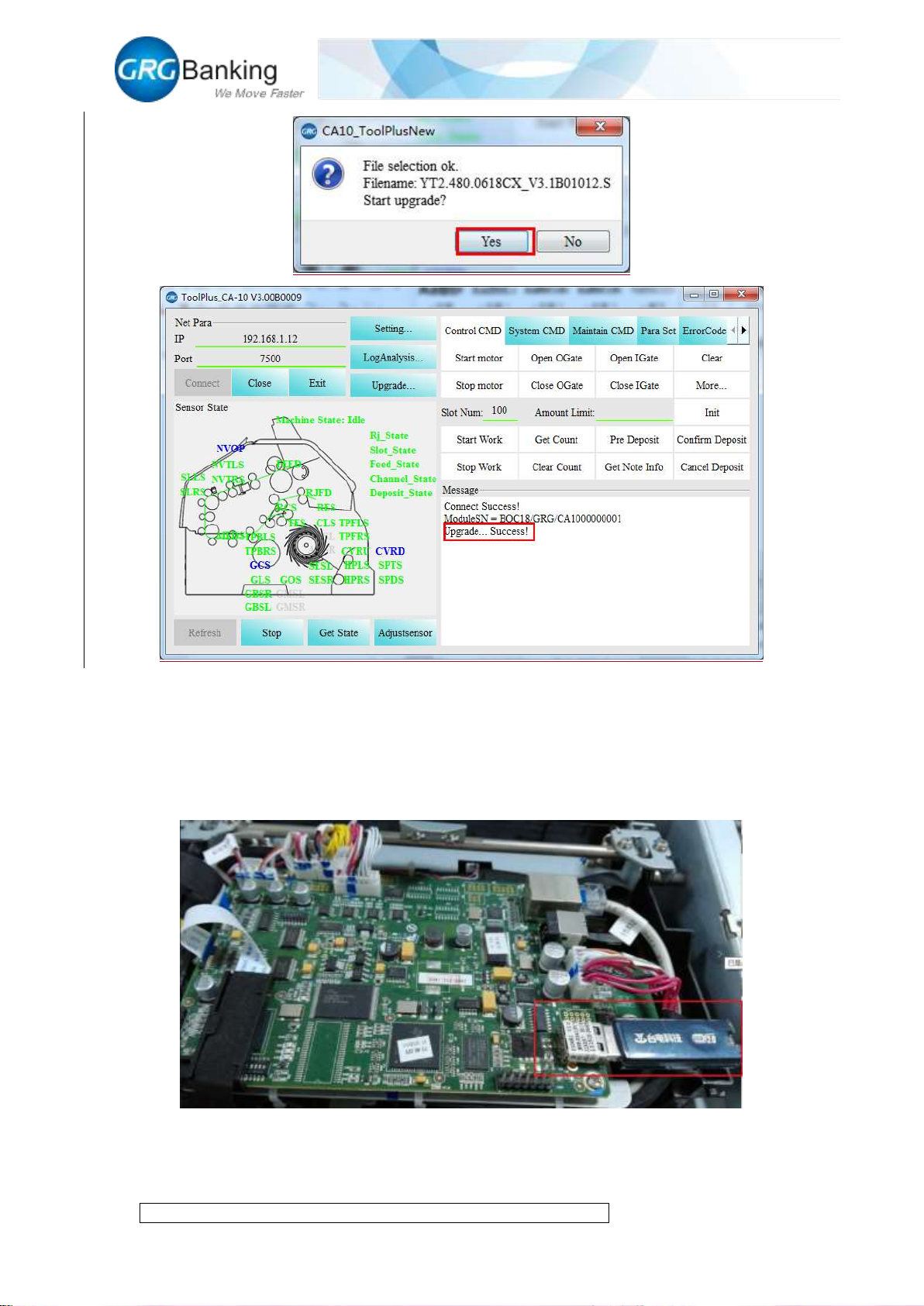
Pitch on the upgrade package of the main control board and then click the “Open” button;
Then it will pop up confirm interface, click “yes” to automatically finish firmware update until the
appearance of “Upgrade success”, click “yes” it will automatically re-connect with CA-10, but if
the connection is failed, please click the “Connect” button and reconnect to PC.
Page 18
Fast Deposit Module CA10 User Manual
Confidential material of GRG, No disclosure to unauthorized Party 15 / 35
4.2 Power-off download (must apply this method when CA10 is unavailable for the lost of the
main control firmware)
Power off CA10 device, copy the main control upgrade file (YT2.480.0618CX_....S) to the root
directory of the USB flash disk, and insert the disk into the U slot on NV board, as shown in the
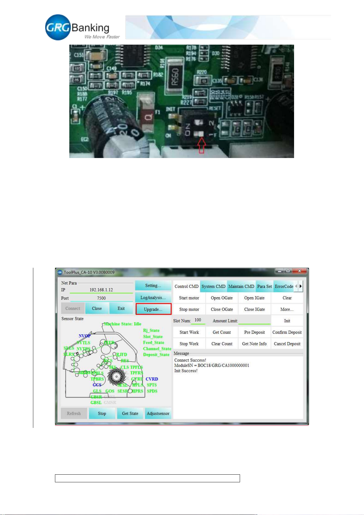
figure below:
Turn pin 1 of the dial switch on the main control board to OFF position, see the following figure:
Page 19
Fast Deposit Module CA10 User Manual
Confidential material of GRG, No disclosure to unauthorized Party 16 / 35
Power on CA10 to upgrade the main control program automatically and rotate the CA10 motor
automatically after the upgrade.
Remove the USB flash disk and turn pin 1 of the dial switch on the main control board to ON
position.
Restart CA10 and connect to PC, view the version and contrast the main control version using the
method of step 7 below. If the version is same as the upgrade file version, it indicates that the
upgrade is successful. If failed, please operate as above again.
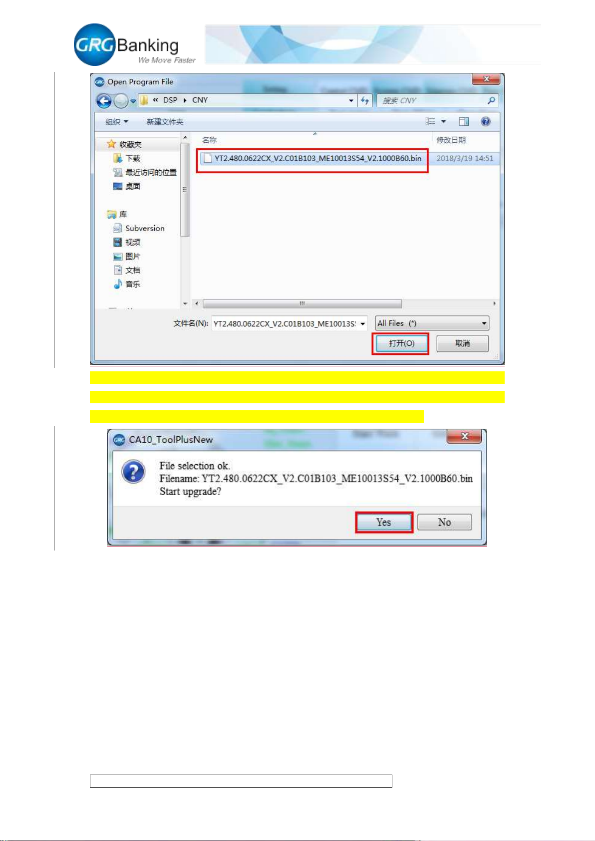
5. Upgrade DSP
Click the “Upgrade” button;
Pitch on the upgrade package of DSP and then click the “Open” button;
Page 20
Fast Deposit Module CA10 User Manual
Confidential material of GRG, No disclosure to unauthorized Party 17 / 35
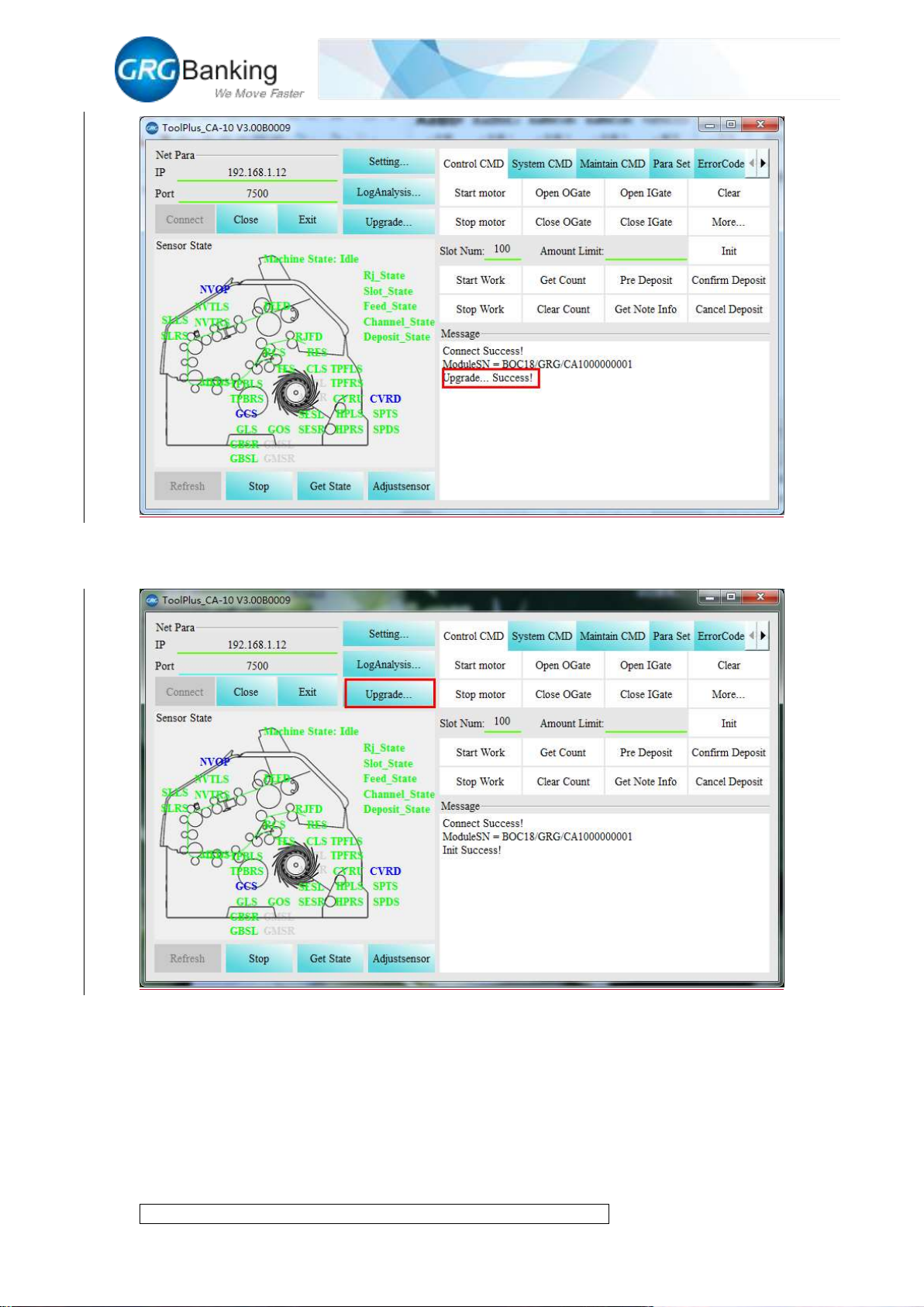
Then it will pop up confirm interface, click “yes” to automatically finish DSP update until the
appearance of “Upgrade success”, click “yes” it will automatically re-connect with CA-10, but if
the connection is failed, please click the “Connect” button and reconnect to PC.
Page 21
Fast Deposit Module CA10 User Manual
Confidential material of GRG, No disclosure to unauthorized Party 18 / 35
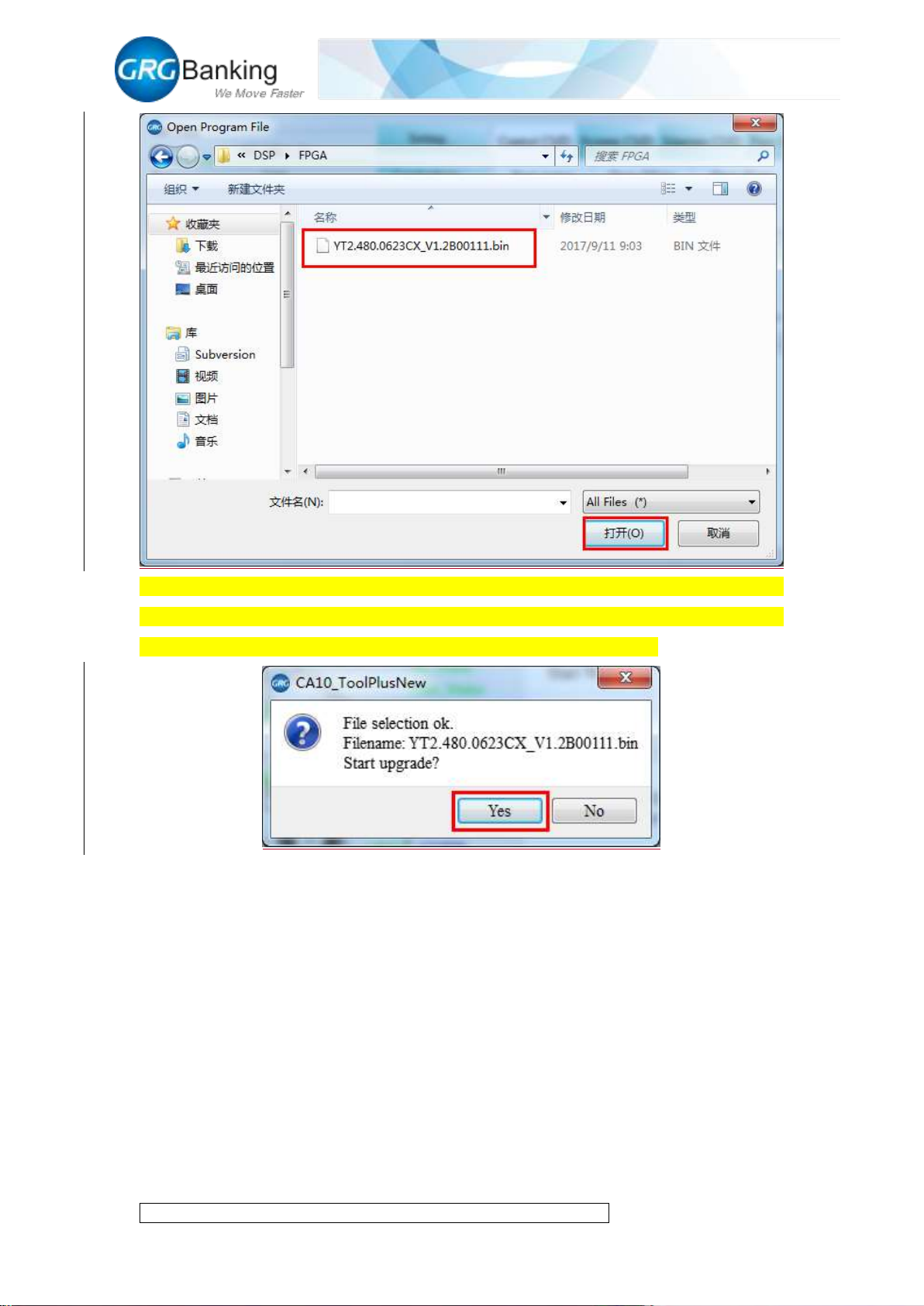
6. Upgrade FPGA
Click the “Upgrade” button;
Pitch on the upgrade package of FPGA and then click the “Open” button;
Page 22
Fast Deposit Module CA10 User Manual
Confidential material of GRG, No disclosure to unauthorized Party 19 / 35
Then it will pop up confirm interface, click “yes” to automatically finish FPGA update until the
appearance of “Upgrade success”, click “yes” it will automatically re-connect with CA-10, but if
the connection is failed, please click the “Connect” button and reconnect to PC.
Page 23
Fast Deposit Module CA10 User Manual
Confidential material of GRG, No disclosure to unauthorized Party 20 / 35
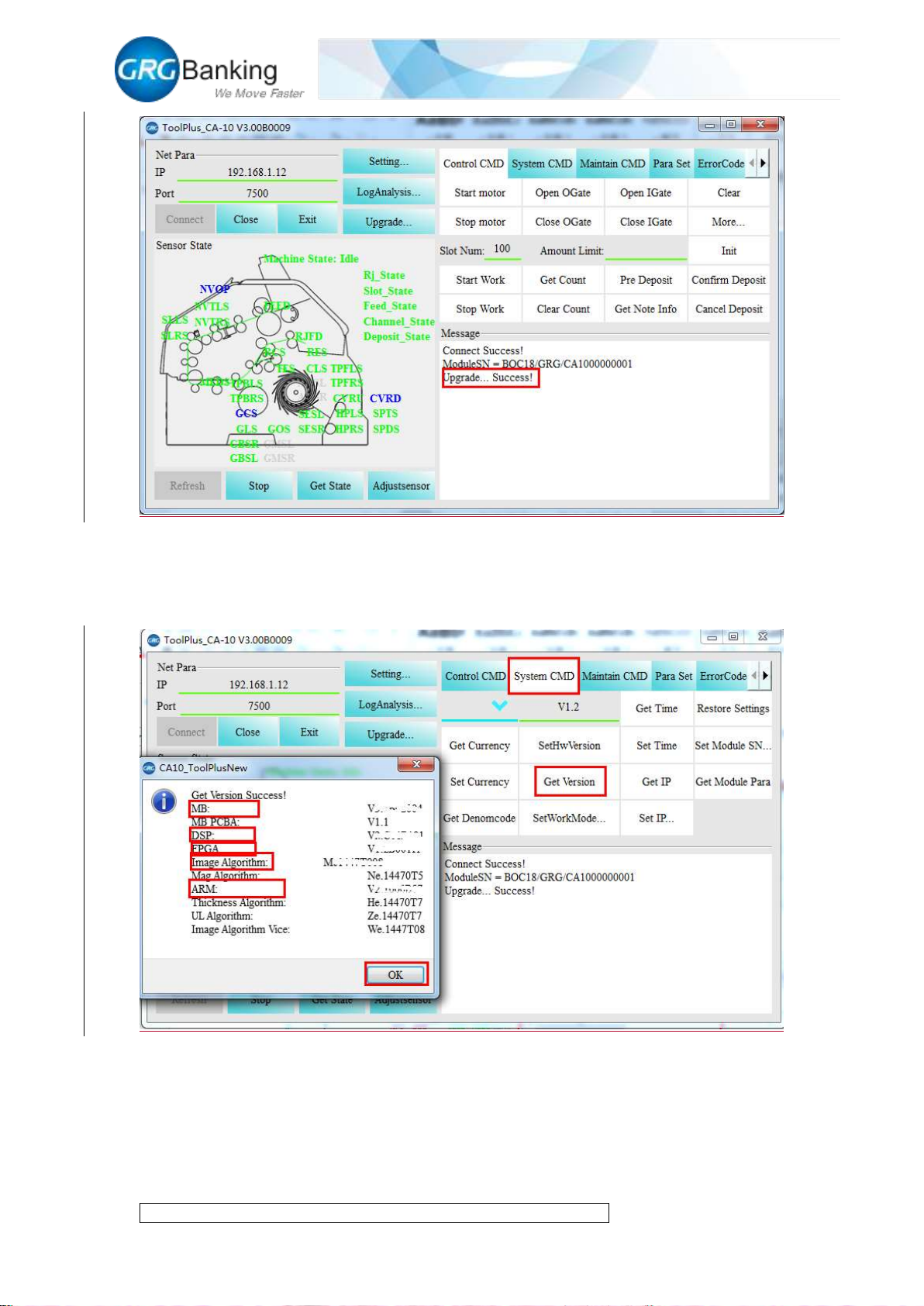
7. View version
After the connection with PC, click “System CMD” and “Get Version” to view correctness of the
upgraded version in the “Message” area.
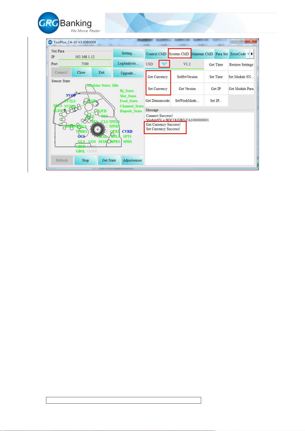
8. Set currency type
Click “System CMD” and “Get Currency” to view currency type supported by DSP currently;
Page 24
Fast Deposit Module CA10 User Manual
Confidential material of GRG, No disclosure to unauthorized Party 21 / 35
Click the drop-down arrow ▼ and select required currency type, click “Set Currency” to finish the
set successfully with the prompt of “Success”.
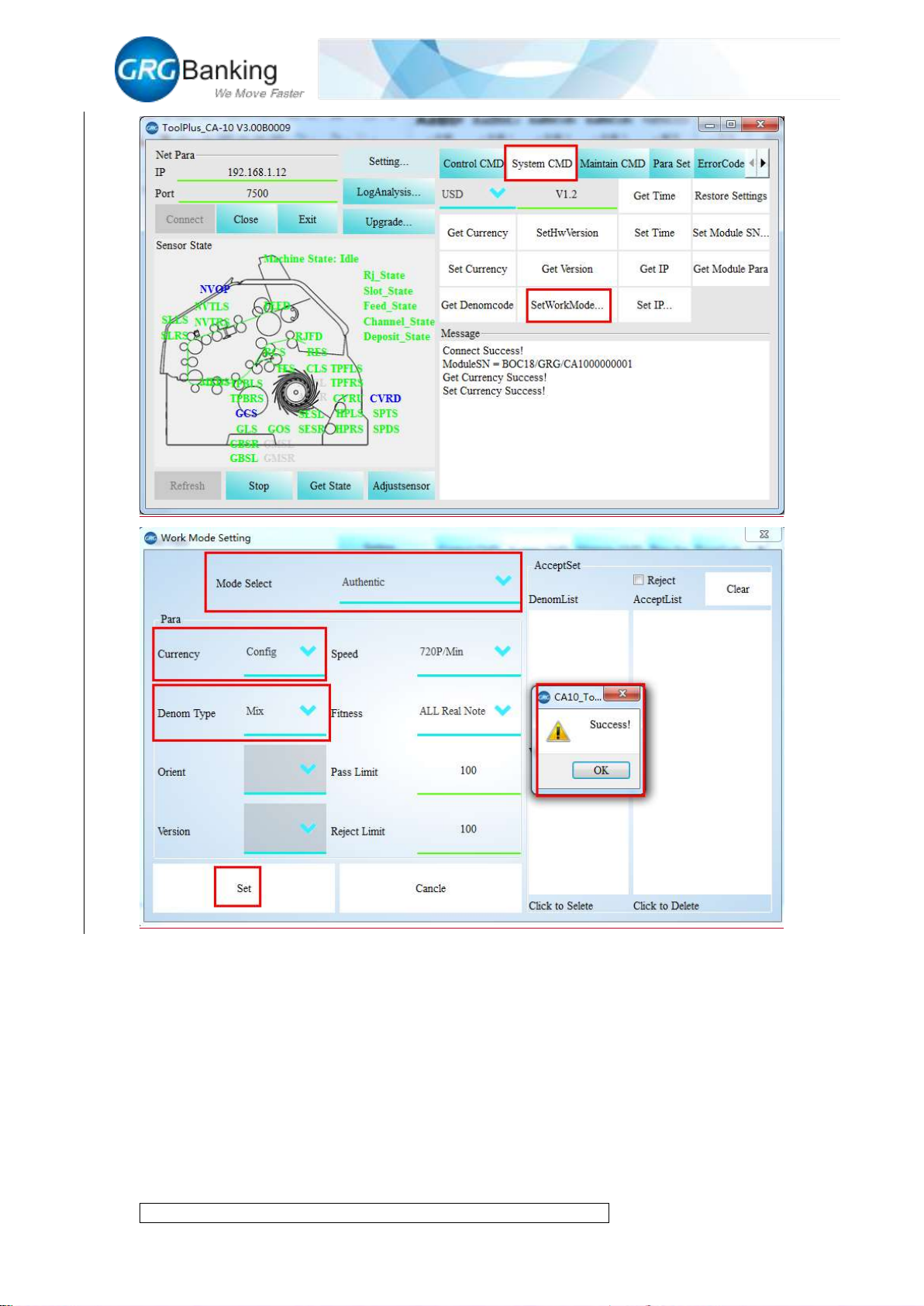
9. Set work model
1) Click “System CMD” and “Set workmode”, and in the pop-up “Parameter set” window,
select the drop-down arrow of “Mode Select” and “Denom Type” to select work modes as
follows:
Authentic: It is mainly used to authenticate notes and identify other properties of the notes,
including currency and denomination;
Counting: Only count the number of the media (including notes, receipts and securities);
Sigal: Set the denomination of note according to the first acceptable note;
Config: Set the denomination accepted or rejected in the reject slot and the escrow slot as
required;
Mix: Do not distinguish the denomination of notes.
2) After the settings, click “OK” and after the prompts of “Success”, click “OK” again.
Page 25
Fast Deposit Module CA10 User Manual
Confidential material of GRG, No disclosure to unauthorized Party 22 / 35
10. Deposit process
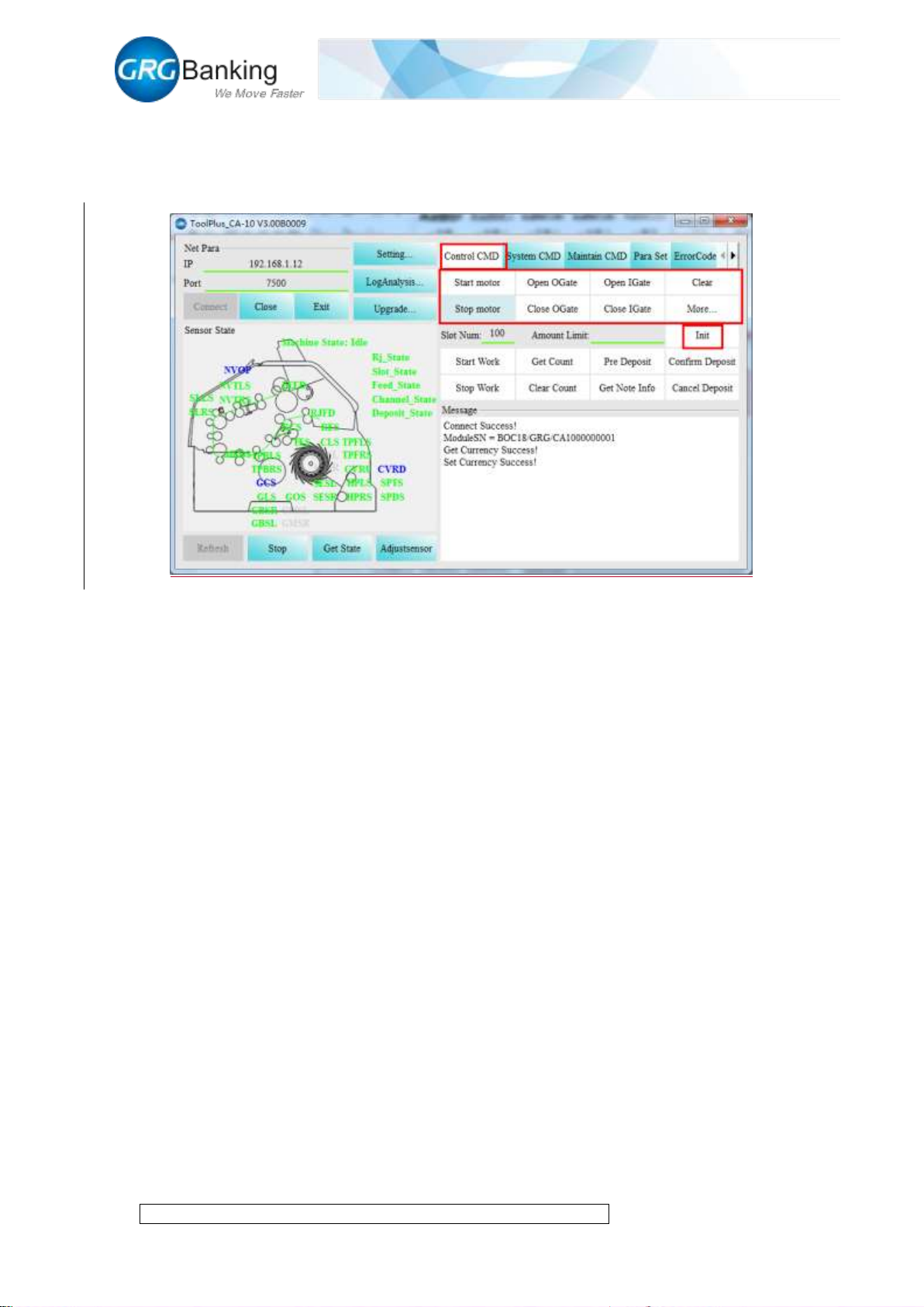
1) Click “Cotrol CMD”, and click the buttons in the red box of the figure below to check
whether each actuator is normal or to debug.
Start motor: To start motor
Stop motor: To stop motor
Open OGate: To open the external shutter
Close OGate: To close the external shutter
Open IGate: To open the internal shutter
Page 26
Fast Deposit Module CA10 User Manual
Confidential material of GRG, No disclosure to unauthorized Party 23 / 35
Close IGate: To close the internal shutter
Clear: To clear the transport
Init: To initialize the process
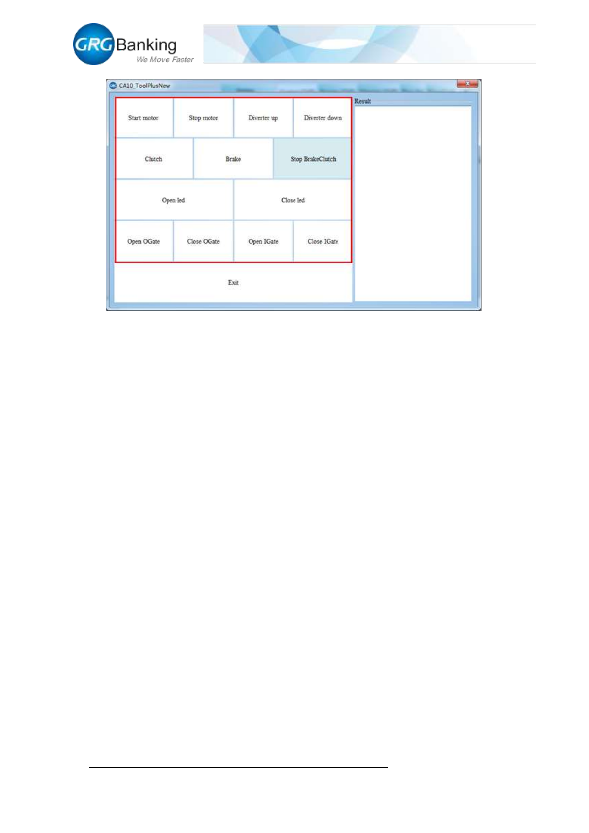
Click “More…” to check more components:
Diverter up: The diverter is in upper position
Diverter up: The diverter is in lower position
Clutch: To clutch
Brake: To brake
Stop Brake Clutch: To brake clutch
LED Open: to open the LED light in the escrow slot
LED Close: To close the LED light in the escrow slot
Page 27
Fast Deposit Module CA10 User Manual
Confidential material of GRG, No disclosure to unauthorized Party 24 / 35
Page 28
Fast Deposit Module CA10 User Manual
Confidential material of GRG, No disclosure to unauthorized Party 25 / 35
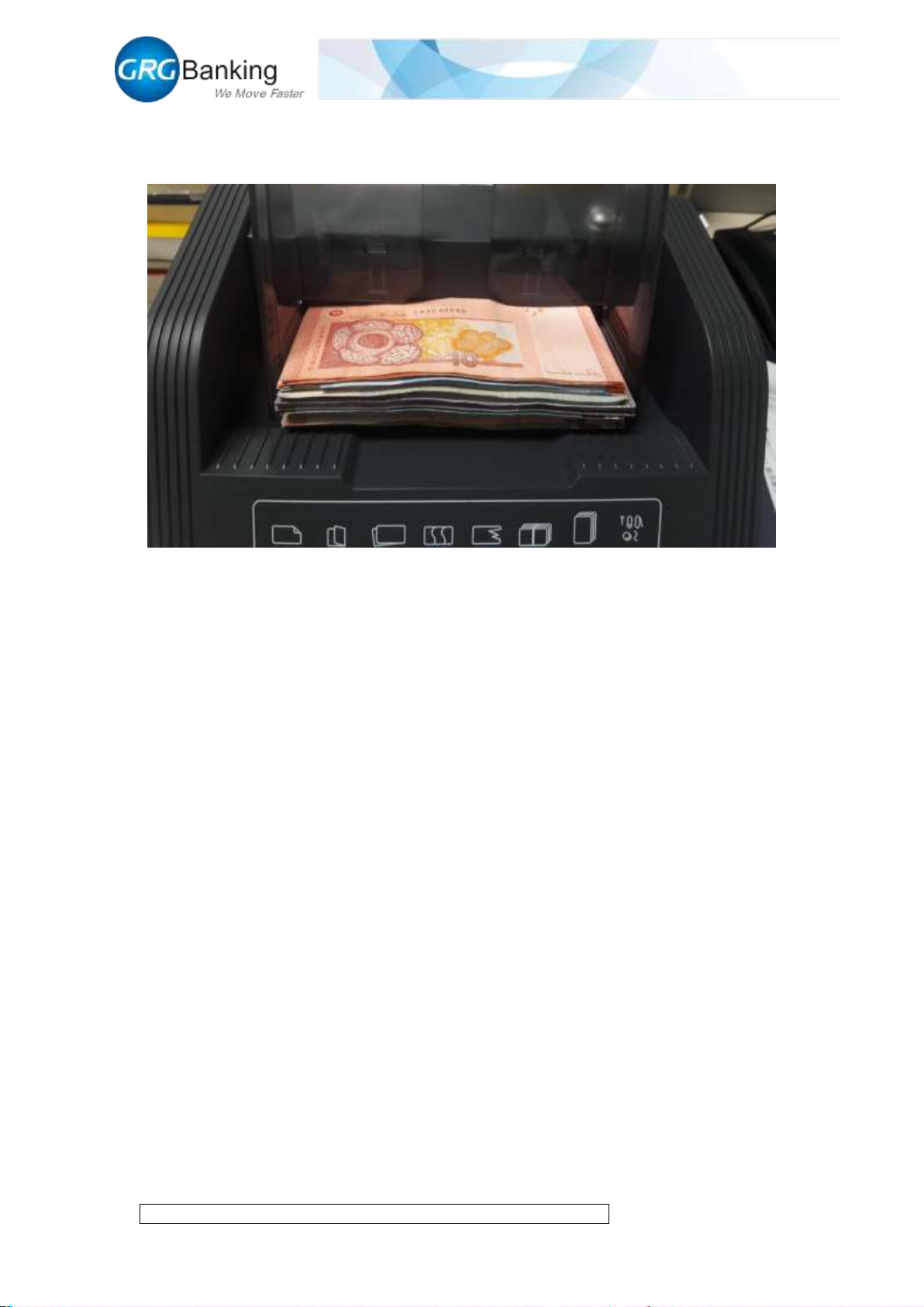
2) Adjust the baffles to match with the width of notes, place notes orderly in the input slot with
a maximum of 500 PCS, and enable to place the notes continuously;
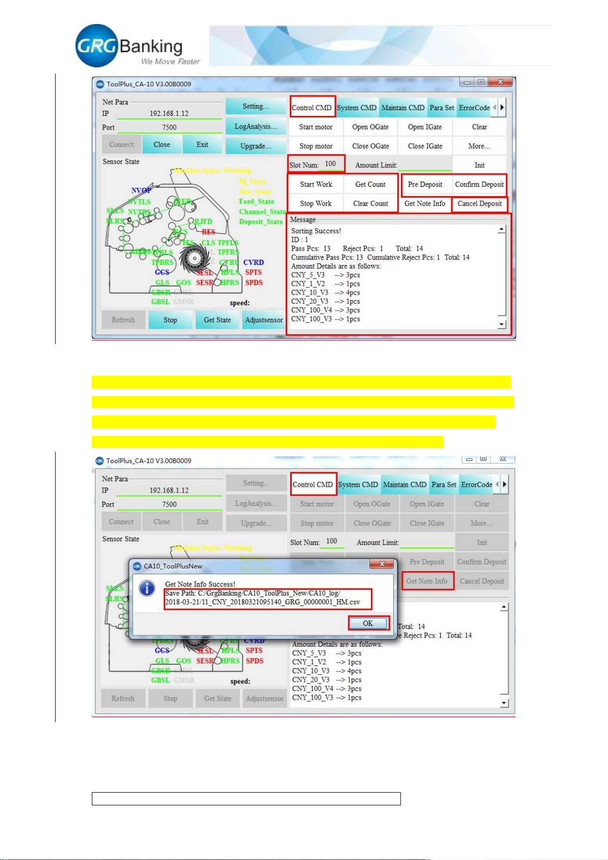
3) Click “Cotrol CMD” and set the note counting capacity of 1-200PCS in the spare area of
“Slot Num” (as required);
4) Click “Start Work” to start to feed acceptable notes into the escrow slot and unacceptable
notes into the reject slot; when the notes in the escrow slot reaches the specified capacity or there
are no notes in the input slot, the note feeding will stop automatically; click “Stop Work” during
the process to stop this note counting.
5) After the notes are fed into the escrow slot, click “Pre Deposit” to press forward the notes
with a pressure plate and move the internal shutter to the specified position. Click “Confirm
Deposit” to deliver the notes to the escrow slot or the output slot; (note: before he “Pre Deposit”
and after the “Confirm Deposit”, the system will report error with the detection of notes stacked
abnormally in the escrow slot, cancel the deposit automatically, and open the external shutter
automatically to take out the notes in the escrow slot; before he “Pre Deposit” and after the
“Confirm Deposit”, click “Cancel Deposit” to open the external shutter automatically and take out
the notes in the escrow slot manually).
6) Before the note counting, click “Auto Mode” to complete automatically the whole process of
“Stop Work-Pre Deposit-Confirm Deposit” for CA10; click “Exitauto Mode” to exit the auto
mode.
7) After the completion of each note counting, display the count information of the current note
counting in the “Message” area; click “Get Count” and “Clear Count” to get and clear the count
information of the current note counting.
Page 29
Fast Deposit Module CA10 User Manual
Confidential material of GRG, No disclosure to unauthorized Party 26 / 35
11. Get the note information
After one note counting, click “Get Note Info” to get the identification information of the current
notes which generates and stores a Excel(.csv) file with a suffix of HM corresponding to the time,
the directory where the files was stored will show in the window. The Excel can be opened to
view the reason of rejecting notes, please provid it to GRG engineers if necessary.
Page 30
Fast Deposit Module CA10 User Manual
Confidential material of GRG, No disclosure to unauthorized Party 27 / 35
12. Compensation image collection
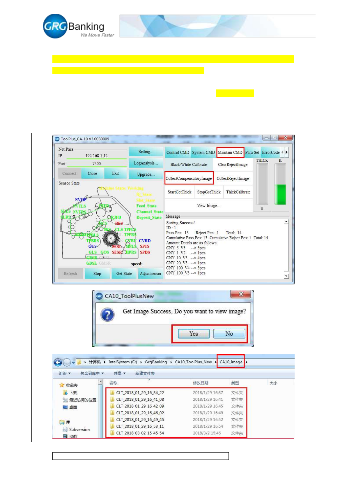
Place the notes required to collect compensation images orderly in the input slot, click “Maintain
CMD” and “Collect Compensatory Image” to feed the notes. Click “Image collect” to enable the
system to collect compensation images of these notes automatically and to store the collected
images in the corresponding CLT folder in the folder named “CA10_image” under the root
directory of “CA10_ToolPlus”. Each collection will generate a folder. Due to the large image files
and long collection time, it is recommended to collect less than 20 images per time.
(Compensation images are only collected to meet the need of GRG engineers).
Page 31
Fast Deposit Module CA10 User Manual
Confidential material of GRG, No disclosure to unauthorized Party 28 / 35
13. Reject image collection
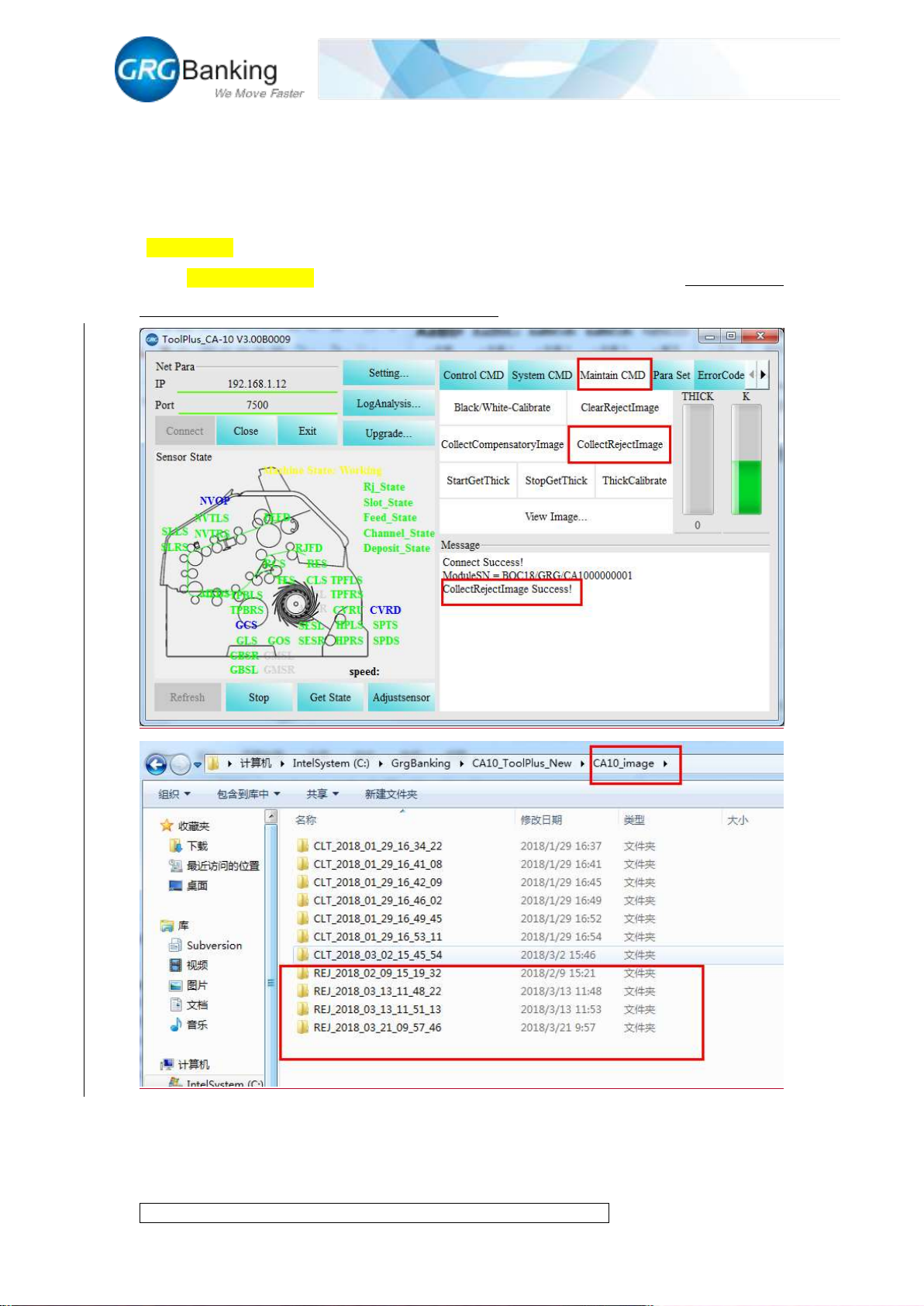
After one note counting, click “Maintain CMD” and “Collect reject image” to get about 20 images
of algorithm reject (subject to the actual quantity if less than 20 images). Generate automatically
an image file after collection and store it in the corresponding folder REJ in the folder named
“CA10_image” under the root directory of CA10_ToolPlus. Each collection will generate a folder.
Click “Clear Reject Image” to clear all stored reject images in the current system. (Reject images
are only collected to meet the need of GRG engineers).
14. Thickness calibration
Refer to Chapter 5 “CA10 Thickness Adjustment Instructions” for the thickness calibration
Page 32
Fast Deposit Module CA10 User Manual
Confidential material of GRG, No disclosure to unauthorized Party 29 / 35
15. Black and white adjustment
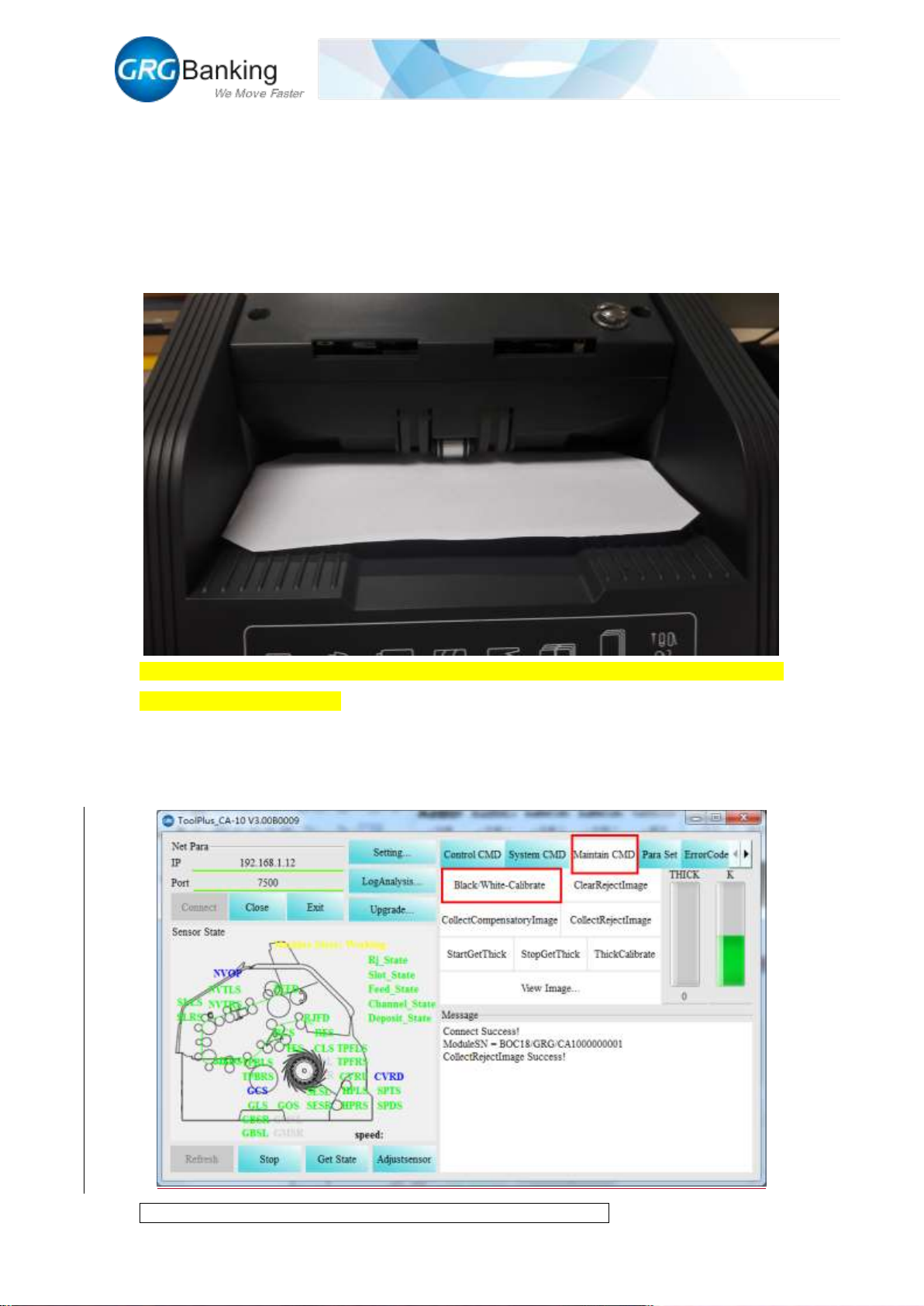
Generally, users do not need perform the black and white calibration in the application of CA10. If
necessary, it shall be performed as follows.
1) Remove the left and right baffles;
2) Place a piece of black and white calibration paper level in the input slot (required to use the
special calibration paper provided by GRG)
3) Click the “Maintain CMD” and “Black/White calibrate” to feed the calibration paper and
complete the black calibration;
4) After finished black calibration, it will automatically pop up a window to remind you
whether to continue the white calibration or not, put the calibration paper in the input slot again
and click “yes” to complete the white calibration;
Page 33
Fast Deposit Module CA10 User Manual
Confidential material of GRG, No disclosure to unauthorized Party 30 / 35
16. Error code query
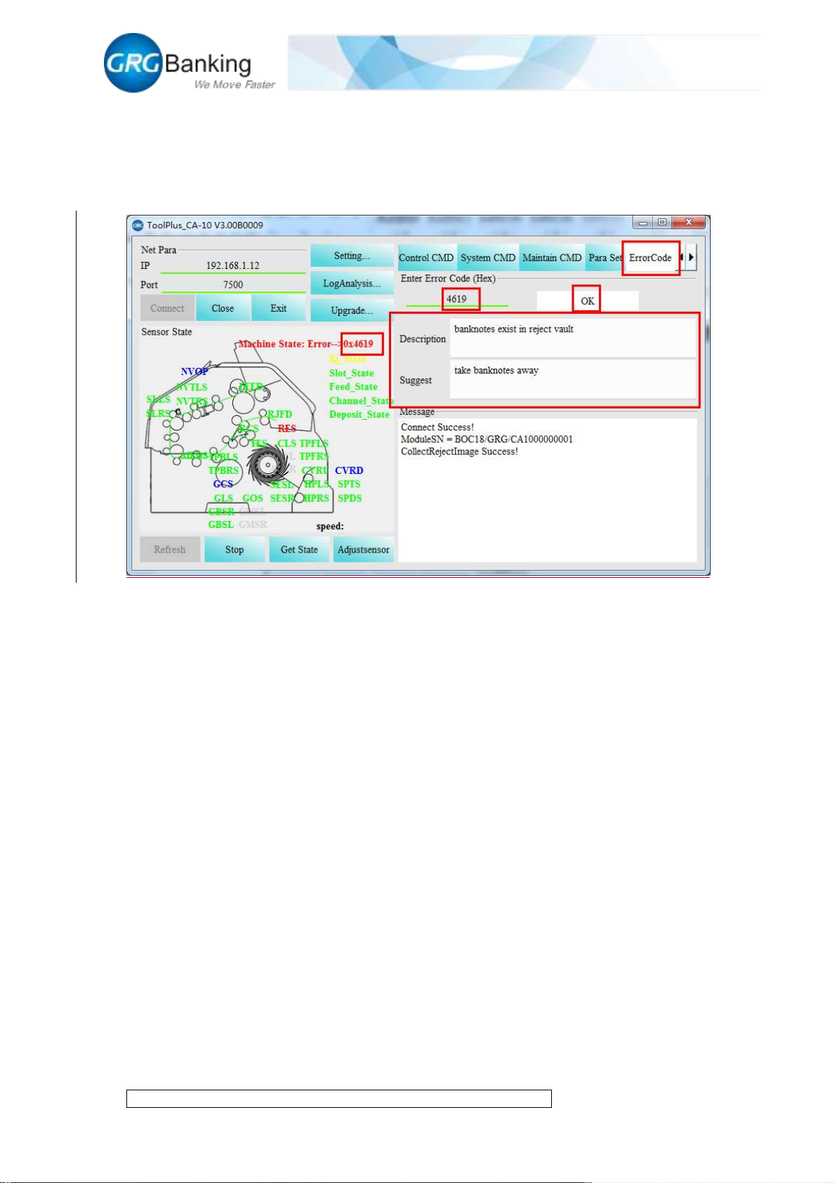
Display an error code when CA10 has a prompt of error, click “Error Code” and input the last 4
characters of the error code to learn more about the error information, click “OK” to get detailed
information about the fault .
Page 34
Fast Deposit Module CA10 User Manual
Confidential material of GRG, No disclosure to unauthorized Party 31 / 35
Chapter 5 CA10 Thickness Adjustment Instructions
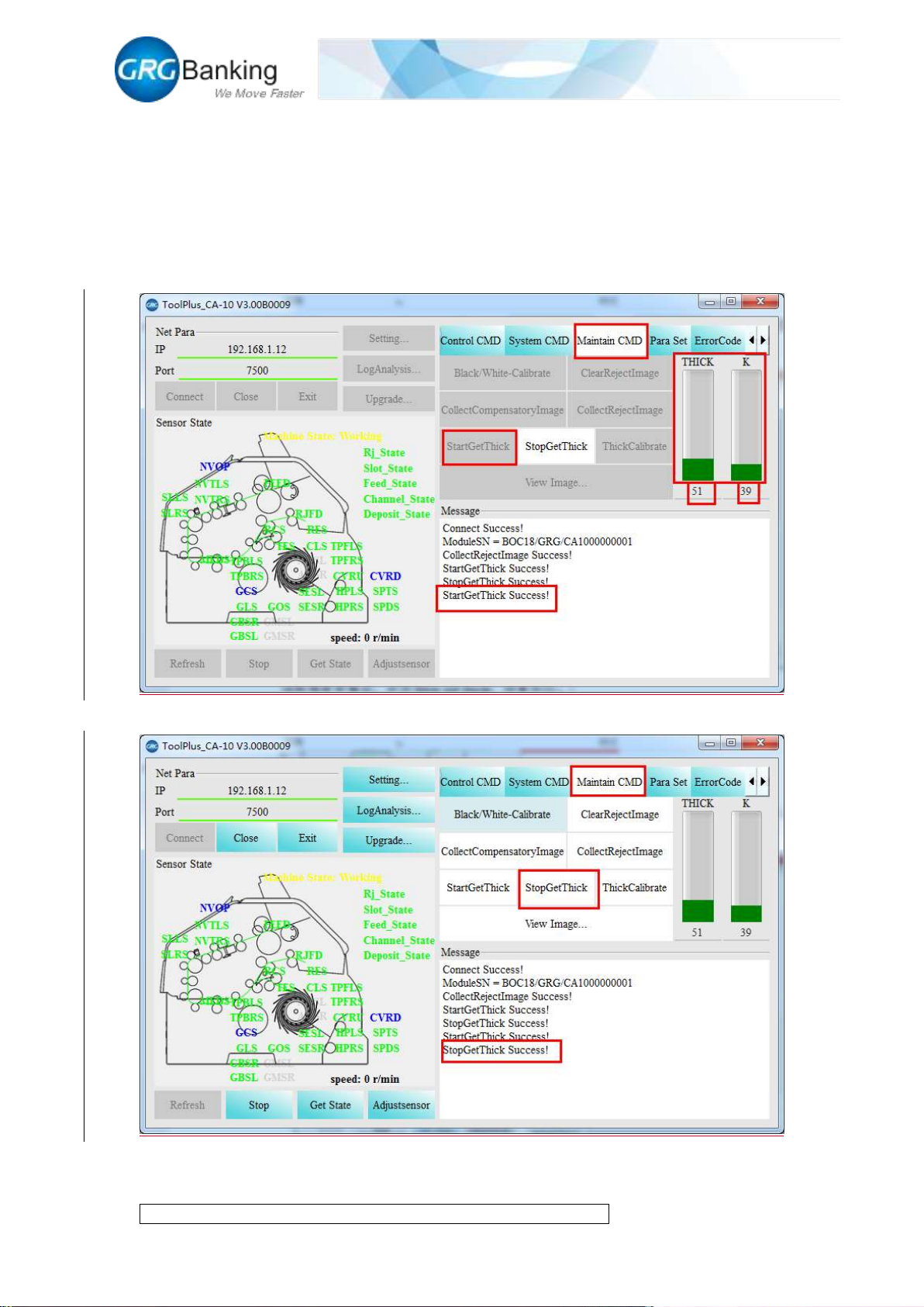
CA10 is adjusted to the qualified state before leaving factory. The qualified thickness zero value is
within 45-65 and the qualified thickness K value is within 30-50.Click “Maintain CMD” and click
“Start get thick” to read the thickness zero value and thickness K value in the histogram or in the
“Message” area.
After read the thickness zero value, click “Stop get thick” to recover the state.
When there are thickness fault or notes are rejected for thickness problems, and the read thickness
zero value and thickness K value is not in the qualified range, adjust the thickness with the
Page 35
Fast Deposit Module CA10 User Manual
Confidential material of GRG, No disclosure to unauthorized Party 32 / 35
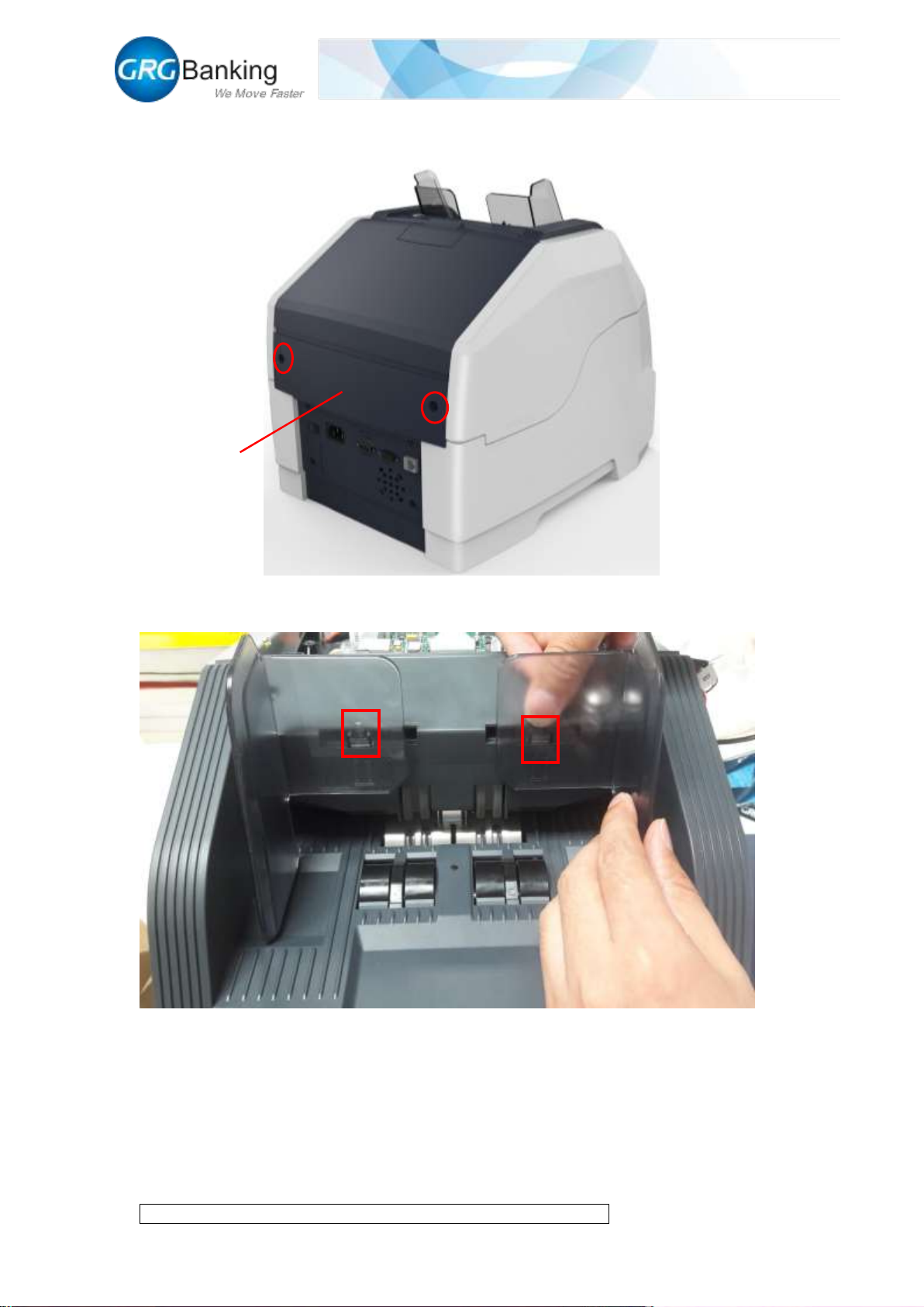
detailed operations as follows:
1) Remove the 2 fixing screws on the back cover plate as well as the back cover plate;
2) As shown in the following figure, press the buckle with one hand and pull out the baffle with
another hand to remove the left and right baffles;
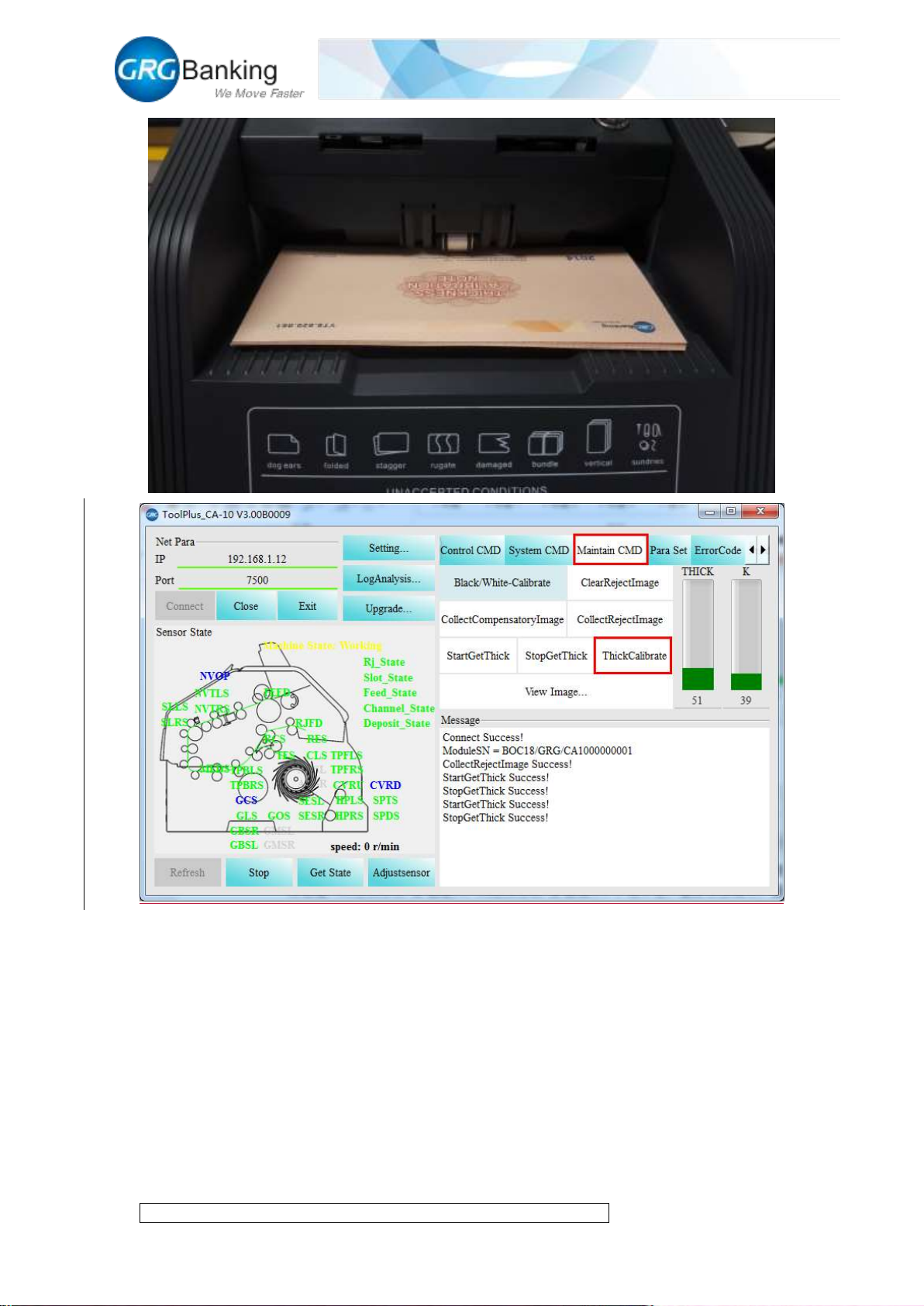
3) Place 10 calibration notes or more with a special thickness of 110 μm in the input slot neatly,
click TIDH and after the calibration notes are fed in, check whether the thickness K value
displayed in the Message area is within 30-50;
Back
cover plate
Page 36
Fast Deposit Module CA10 User Manual
Confidential material of GRG, No disclosure to unauthorized Party 33 / 35
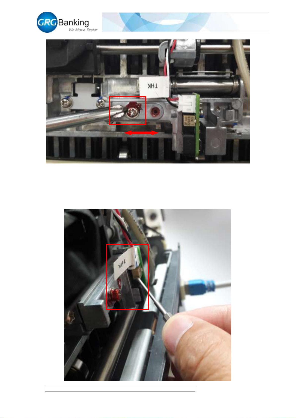
4) If the thickness K value is not in this range, unscrew the M3 combination screws shown in
the following figure with a screwdriver, slight adjust the thickness base position around and
tighten the screws again. Repeat the step 3) until the thickness K value is in the range of
30-50, and repeat the step 3) twice to achieve a successful thickness calibration in which the
fluctuation difference of the three thickness K values is less than 5.
Page 37
Fast Deposit Module CA10 User Manual
Confidential material of GRG, No disclosure to unauthorized Party 34 / 35
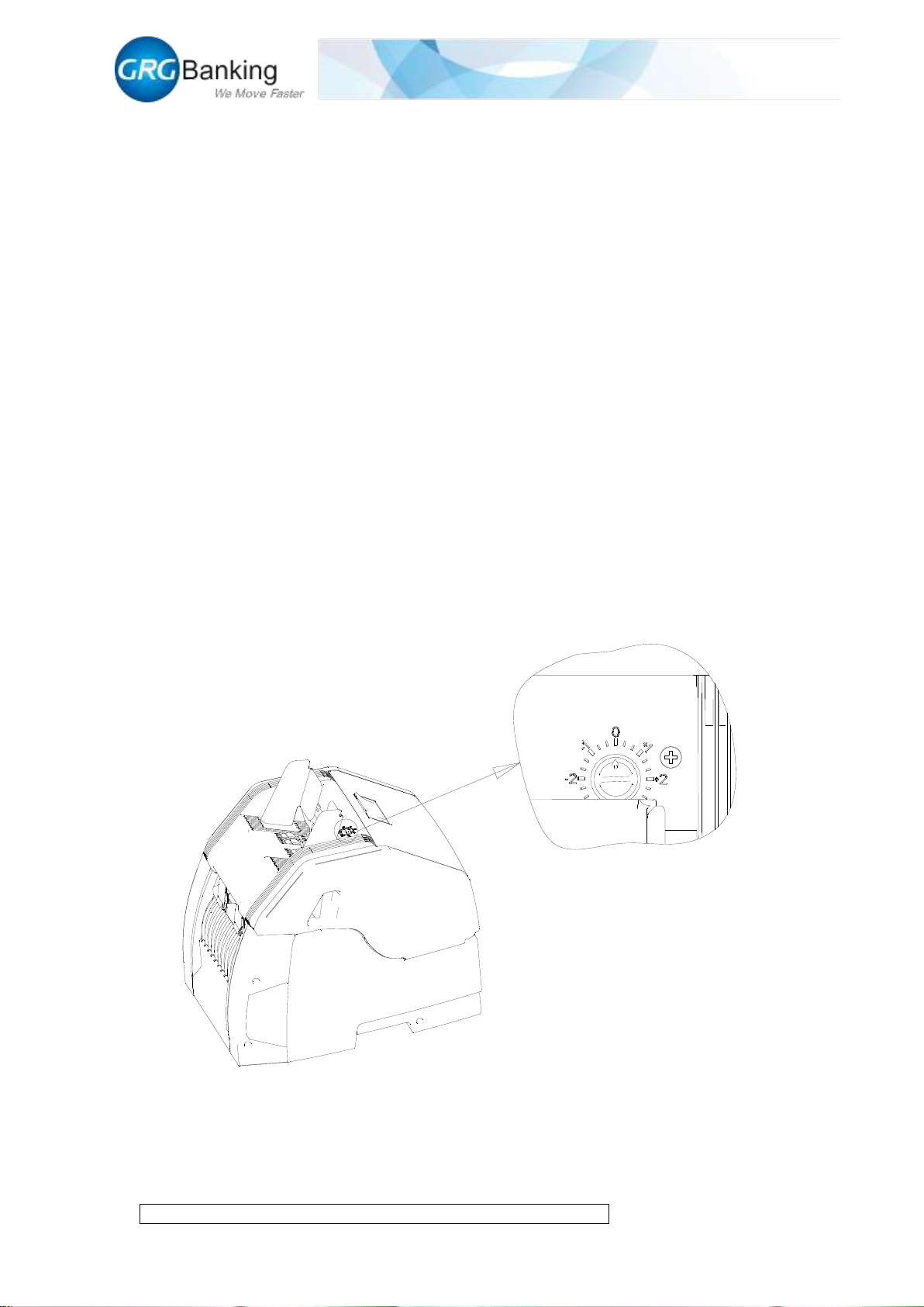
5) Continue to click “Start get thick” and read whether the thickness zero value is in the range
of 45-65; if not, rotate the potentiometer adjusting screws with a small slotted screwdriver
and adjust to the qualified range (clockwise is to decrease and anticlockwise is to increase);
click “Stop get thick” after this adjustment and reset the back cover plate after the whole
thickness adjustment.
Page 38
Fast Deposit Module CA10 User Manual
Confidential material of GRG, No disclosure to unauthorized Party 35 / 35
Chapter 6 CA10 Note Feeding Clearance Adjustment Instructions
The CA10 note feeding clearance is adjusted to the state of enabling to adopt most notes before
leaving factory, so maintenance staff or clients just have to perform slight adjustment if necessary.
It shall be done as follows:
Step 1, determine whether the note feeding clearance is reasonable:
Set the CA10 model as “count mode”, test the counting with 1,000 notes of 70% and 80% new
normal 100 yuan.
a. If the note feeding clearance is too tight, easily to observe the conditions that the notes are
not loaded smoothly and the counting is not continuous.
b. If the note feeding clearance is too loose with overlapped and consecutive notes, easily to
observe that the reject bin counts two or more notes at the same time, and view the reject reasons
including “wrong transportation” and “the note is too thick”;
c. It is qualified if the rejected notes are no more than three. Otherwise, slight adjustment of the
clearance is required.
Step 2, slight adjustment of the clearance
The slight adjustment of note feeding clearance shall be done as follows.
The clearance is too loose:
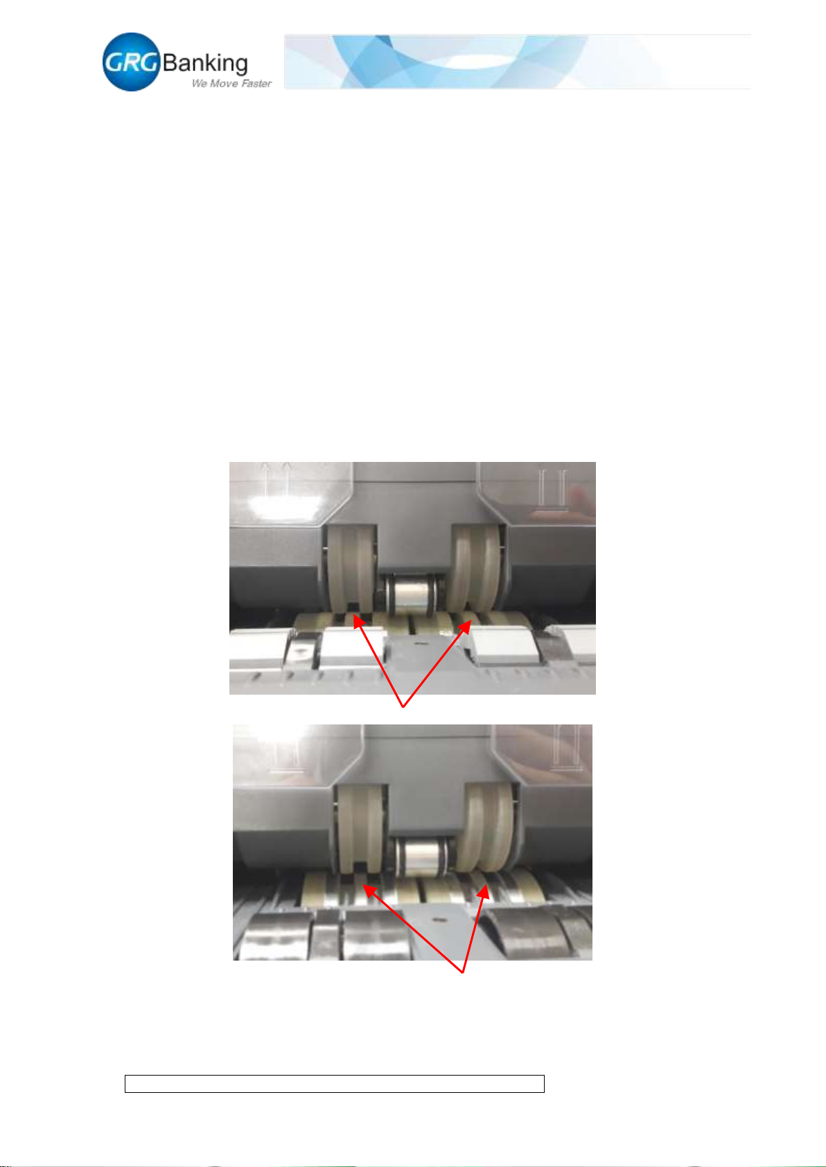
Rotate the “adjusting knob of note feeding clearance” (the metal piece with a slotted groove as the
Page 39
Fast Deposit Module CA10 User Manual
Confidential material of GRG, No disclosure to unauthorized Party 36 / 35
figure above) anticlockwise with a slotted screwdriver or a coin to adjust by a small space,
ensuring the machine is in the “count” mode after the adjustment, and test the note counting with
1,000 notes of 70% and 80% new 100 yuan to determine as above.Adjust repeatedly to applicable
state
Note: the “left and right width adjustment plates” have to be installed in the test process and the
width between the plates is adjusted to be available for 100 yuan.
The clearance is too tight: Adjust in the opposite direction of too loose above.
Or refer to the experience adjustment method as follows:
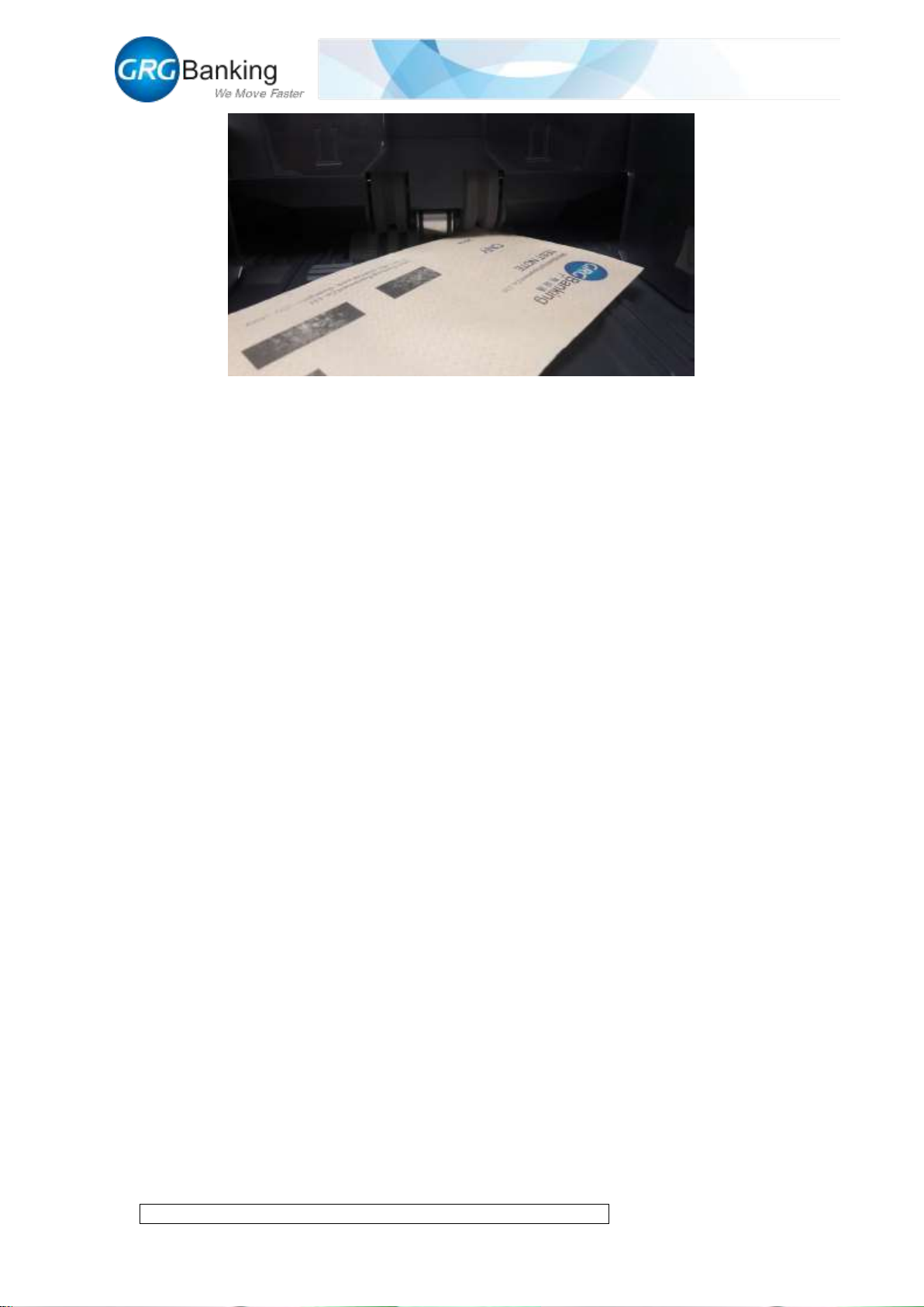
Insert notes into feeder roller to test the clearance while turning the scale; the standard is that notes
can not be fed as the rubber wheel groove is upwards; the notes can be fed as the rubber wheel is
downwards, and when pull out the notes, the wheel will rotate with notes ; or adjust it to the state
without overlapped, consecutive or inclined notes.Determine as mentioned above after the
adjustment.
Groove of rubber wheel
upward
Groove of rubber wheel
downward
Page 40
Fast Deposit Module CA10 User Manual
Confidential material of GRG, No disclosure to unauthorized Party 37 / 35
Chapter 7 Overall Development Support
We provide CA10 to users in a manner of module and we also can provide dynamic development
library SDK files of CA10 to facilitate a rapid overall development for users.
 Loading...