

Greystone Energy Systems ULP1, ULP2 Installation Instructions Manual
Ultra Low Pressure Transmitter
ULP
Installation Instructions
Introduction
The Ultra Low Pressure Transmitter is used to measure dierential
pressure in the range of 0.125 to 1"wc (30 to 250 Pa). It combines
precision high sensitivity silicon sensing capabilities and the latest ASIC
technology to substantially reduce oset errors due to changes in
temperature, stability to warmup, long term instability and position
sensitivity. It is ideal for monitoring pressure for air or other clean inert
gas. It features several eld selectable uni- or bi-directional pressure
ranges and output signal types for the most exible application. The
device has an on-board auto-zero function as well as a connection for
remote zeroing. Options include an LCD to display the pressure value
and an alarm relay with a variable trip point.
Before Installation
Read these instructions carefully before installing and commissioning the Pressure Transmitter. Failure to follow these instructions
may result in product damage. Do not use in an explosive or hazard-
ous environment, with combustible or ammable gases, as a safety or
emergency stop device or in any other application where failure of the
product could result in personal injury. Take electrostatic discharge
precautions during installation and do not exceed the device ratings.
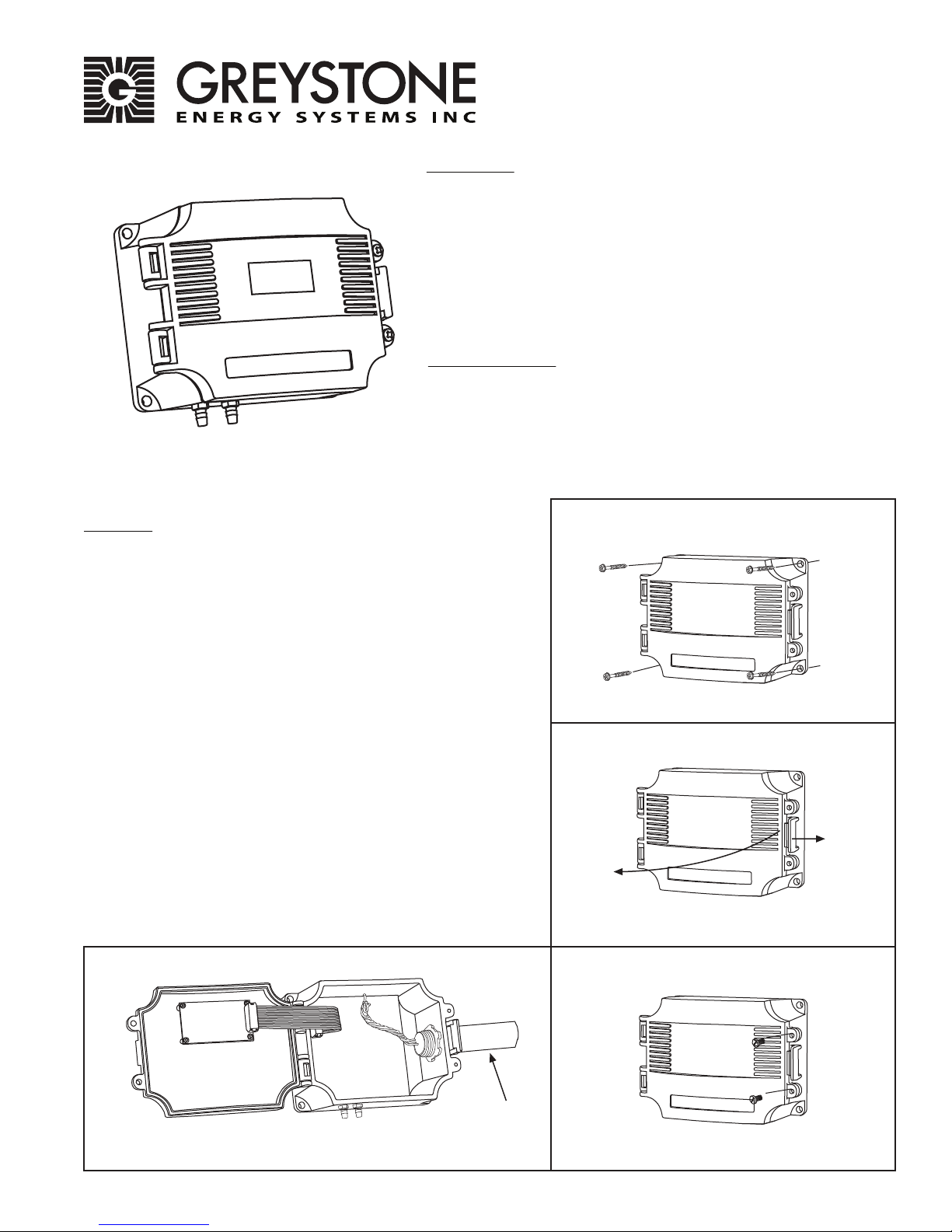
Mounting
Mount the device using the four holes on the base of the unit. Leave
enough space around the unit to connect the pressure tubing and
avoid locations with severe vibrations, excessive moisture or rapid
temperature changes. It should be mounted on a vertical surface with
the pressure ports on the bottom and the cable entrance on the right.
The enclosure has a standard ½” conduit opening and may be installed
with either conduit and a conduit coupler or a cable gland type tting.
Open the hinged cover by releasing the latch and connect the device
according to the wiring instructions. After wiring and setup are
complete, close and latch the cover. The cover may be secured with
two self-tapping screws in the holes provided. as shown in gure 1.
The enclosure has a hinged cover with latch. Open cover by pulling
slightly on the latch on the right side of the enclosure. At the same
time pulling on the cover, as illustrated in gure 2.
Feed conduit/cable gland tting through the provided hole in side of
enclosure and secure with a lock nut as show in gure 3. It is recommended that weatherproof conduit or cable gland ttings be used.
Make wiring connections as per the “Wiring” illustrations on Page 3.
Swing door closed until securely latched. For added security, 2 screws
are provided that may be installed in the integrated screw tabs. See
gure 4.
Figure 1
Figure 2
Figure 4Figure 3
Greystone Energy Systems, Inc. 150 English Drive, Moncton, NB E1E 4G7 Canada Tel: +1-506-853-3057 Tollfree (North America): +1-800-561-5611 Fax: +1-506-853-6014
Conduit
Email: support@greystoneenergy.com Web: www.greystoneenergy.com
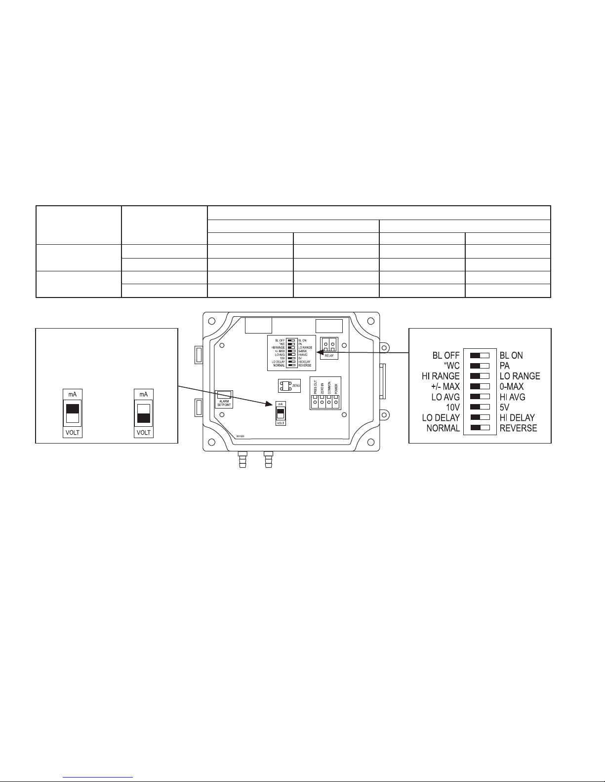
Hardware Setup
The analog output type must be set before the device is connected. Slide the switch labelled VOLT and mA to the correct
position for the required output signal type, either 4-20 mA or 0-5/10 Vdc. See gure 5. Other parameters may be set on the
DIP switches before or after the device is connected. Any DIP switch change will have an immediate eect on the operation.
DIP Switch Conguration (See gure 6)
BL OFF / BL ON Sets the LCD backlight on or o
"WC / Pa Sets the pressure units to “WC or Pascals
HI Range / LO Range* Sets the pressure range (See chart below)
+/- Max / 0 - Max Sets bi- or uni-directional pressure range
LO Avg / HI Avg Sets pressure averaging to 5 or 30 seconds
10V / 5V Sets the voltage output scale to 0-5 or 0-10 Vdc (N/A when mA output is selected)
LO Delay / HI Delay Sets the alarm delay to 10 or 60 seconds (N/A if no relay is ordered)
Normal / Reverse Sets the alarm action (N/A if no relay is ordered)
*The eect of dierent DIP switch settings on the pressure range is shown in the following table.
Model
Pressure Pressure ULP*1 ULP*2
Units Range ± Max 0 - Max ± Max 0 - Max
"WC HI Range ± 1 "wc 0-1 "wc ± 0.25 "wc 0-0.25 "wc
LO Range ± 0.5 "wc 0-0.5 "wc ± 0.125 "wc 0-0.125 "wc
Pa HI Range ± 250 Pa 0-250 Pa ± 60 Pa 0-60 Pa
LO Range ± 125 Pa 0-125 Pa ± 30 Pa 0-30 Pa
Figure 5
Output Type Selection Switch
mA = 4-20 mA
(Factory Default)
VOLT = Vdc
Figure 6
Wiring Instruction
The transmitter has standard screw block connectors. Use shielded twisted pair wiring of at least 22 AWG for all connections
and do not run device wires in the same conduit with wiring used to supply inductive loads such as motors. Disconnect the
power supply before making any connections to prevent electrical shock or equipment damage. Make all connections in
accordance with national and local electrical codes.
This is a 3-wire sourcing device. Connect the positive dc or the ac voltage hot side (24 Vac/dc ± 10%) to the POWER terminal.
The supply common is connected to the COMMON terminal. The device is reverse voltage protected and will not operate if
connected backwards. It has a half-wave rectied power supply so the supply common is the same as the signal common.
Several devices may be connected to one power supply and the output signals all share the same common. Use caution when
grounding the secondary of a transformer or when wiring multiple devices to ensure the ground point is the same on all
devices and the controller.
The analog output is available on the PRES OUT terminal. This signal is switch selectable for either voltage or 4-20 mA active
output. In voltage mode the output is 0-5 or 0-10 Vdc. These options are indicated on the circuit board. The current output
operates in the Active mode and does not require a loop power supply. This means the signal current is generated by the
transmitter and must not be connected to a powered input or device damage will result. Check the controller Analog Input to
determine the proper connection before applying power. Both current and voltage signals are referenced to the COMMON
terminal. The voltage output signal has a minimum load that it is able to drive, similarly the current signal has a maximum
load. Follow the ratings in the Specication section or inaccurate readings may result. See gure 7.
The RELAY output is a normally open dry contact. This signal can be used to directly control an alarm, ventilation fan or may
be connected to a digital input of the BAS for status monitoring. Ensure any loads connected to the relay is within the relay
rating in the Specication section. See gure 8.
The remote zero feature may be used by wiring a dry-contact (relay only) digital output between the ZERO IN and COMMON
terminals. Do not apply voltage to the ZERO IN terminal. See gure 9.
Greystone Energy Systems, Inc. 150 English Drive, Moncton, NB E1E 4G7 Canada Tel: +1-506-853-3057 Tollfree (North America): +1-800-561-5611 Fax: +1-506-853-6014
Email: support@greystoneenergy.com Web: www.greystoneenergy.com
 Loading...