

Greystone Energy Systems TXRCL Installation Manual
TXRCL Temperature Transmitter with LCD Installation Manual
Introduction
The TXRCL transmitter incorporates a temperature transmitter
in an attractive wall mount enclosure for the most efficient
environmental monitoring and control system. It uses a curvematched thermistor to measure temperature. The device may
also include an occupancy override button and an external
communication jack. The output is available as a linear 4-20
mA, 0-5 or 0-10 Vdc signal.
An LCD is included for configuration and local indication of all
parameters. Several operating parameters can be programmed using a keypad for specific applications including four
temperature ranges and C/F display.
Before Installation
Read these instructions carefully before installing and commission ing the device. Failure to follow these instructions may
result in product damage. Do not use in an explosive or hazardous environment, with combustible or flammable gases, as a
safety or emergency stop device or in any other application where failure of the product could result in personal injury. Take
electrostatic discharge precautions during installation and do not exceed the device ratings.
Mounting
The room type sensor installs directly on a standard electrical box and should be mounted about five feet from the floor of the
area to be controlled. Do not mount the sensor near doors, opening windows, supply air diffusers or other known air
disturbances.
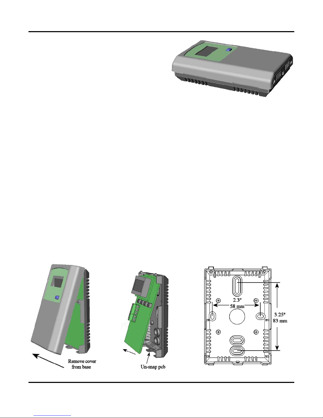
The cover is hooked to the base at the top edge and must be removed from the bottom edge first. Use a small screwdriver to
carefully pry each bottom corner if necessary. If a security screw is installed on the bottom edge, then it may have to be
loosened or removed also. Tip the cover away from the base and sit it aside.
The pcb must be removed from the base to access the mounting holes. Follow usual anti-static procedures when handling the
pcb and be careful not to touch or bend the sensors. The pcb is removed by pressing the tab on the enclosure base to unsnap
the latch near the bottom edge, then the pcb can be lifted out of the base. Sit the pcb aside until the base is mounted on the
wall.
After the base is screwed to an electrical box or the wall using the appropriate holes, pull the wires through the wiring hole in
the center of the pcb and then gently reinstall it in the enclosure b ase. Ensure the pcb is snapped into the base securely and
correctly. The mounting hole locations are shown in the follo wing drawing.
August 8, 2014
1

TXRCL Temperature Transmitter with LCD Installation Manual
Wiring
Deactivate the 24 Vac/dc power supply until all connections are made to the device to prevent electrical shock or equipment
damage. Follow proper electrostatic discharge (ESD) handling procedures when installing the device or equipment damage
may occur.
Use 22 AWG shielded wiring for all connections and do not locate the device wires in the same conduit with wiring used to
supply inductive loads such as motors. Connect the cable shield to ground at the contro ller only. Make all connections in
accordance with national and local codes.
This is a sourcing device and requires 3 to 11 wires depending on features ordered. Connect the plus dc or the ac voltage hot
side to the POWER terminal. The power supply common is connected to the COMMON terminal. The device is reverse
voltage protected and will not operate if connected backwards. It has a half-wave power supply so th e supply common is the
same as the signal common. Several devices may be connected to one power supply and the output signals all share the same
common. Use caution when grounding the secondary of a transformer or when wiring multiple devices to ensure the ground
point is the same on all devices and the controller.
The analog output is available on the TEMP OUT terminal. For 4-20 mA output type, all outputs operate in the Active mode
and do not require a loop power supply. This means the signal current is generated by the transmitter and must not be
connected to a powered input or device damage will result. Check the controller Analog Input to determine the proper
connection before applying power. All output signals are referenced to the COMMON terminal. The analog output signals
are typically connected directly to the Building Automation System and used as control parameters or for logging purposes.
The device is also available with 0-5 or 0-10 Vdc voltage signal outputs which connect directly to a high impedance analog
input. In either case the terminal designations are the same and the signals are referenced to COMMON.
The OCC IN terminal is a digital input that controls the OCC segment on the LCD to indicate an occupied condition. It can
be connected to a 0/5V digital signal or a dry contact signal. This is usually an active low input signal and requires that the
OCC IN terminal be shorted to COMMON to activate the input.
The override switch output is a dry-contact and is available on the SWITCH + and SWITCH – terminals. It is typically
connected to a low-voltage digital input on the controller to indicate room occupancy or override when the button is
activated.
The resistive fan speed output signal is available on the FAN + and FAN – terminals and has five positions.
The external jack is internally connected to a three-pin terminal b lock labeled RING, MID and TIP to accept a stereo phono
plug for remote communication with the controller.
Start-up
Verify that the transmitter is properly wired and connections are tight. Apply power and note that the LCD will begin
displaying the temperature levels. All the output signals will also be available immediately after start-up.
LCD Display
The device is configured to display the temperature continuously. The Setup Menu can be used to modify the displayed
information. The device supports four temperature ranges that may be selected in the menu. The default is 0-35 C but this
may be changed to 32-95 F and the output signal will stay the same. Also, the temperature range may be changed to 32-122
F or 0-50 C and the output signal scaling will change to match the display.
Output
The temperature output is scaled such that 4-20 mA (or 0-5 or 0-10 Vdc) equals either 0-35 C, 32-95
F depending on which range is selected in the menu. The factory defa ul t ra nge is 0- 35 C.
F, 0-50 C or 32-122
August 8, 2014
2
 Loading...