

Greystone Energy Systems HRC Series, HRC-INS-001 Installation Instructions Manual
HRC Series RH Transmitter
Installation Instructions
Introduction
The room RH transmitter uses a highly accurate and eld-proven RH
sensor in an attractive, low prole enclosure to monitor room relative
humidity levels. Additional options include an occupancy override
button, a communication jack, a fan speed switch, a slide-pot setpoint
control, a resistive temperature sensor and a LED or LCD display. The RH
output can be selected as a linear 4-20 mA, 0-5 or 0-10 Vdc signal.
Before Installation
Read these instructions carefully before installing and commissioning
the device. Failure to follow these instructions may result in product
damage. Do not use in an explosive or hazardous environment, with
combustible or ammable gases, as a safety or emergency stop device
or in any other application where failure of the product could result in
personal injury. Take electrostatic discharge precautions during installation and do not exceed the device ratings.
Mounting
The room RH transmitter installs directly on a standard electrical box and should be
mounted ve feet from the oor of the area to be controlled. Do not mount the sensor
near doors, opening windows, supply air diusers or other known air disturbances.
Avoid areas where the detector is exposed to vibrations or rapid temperature
changes.
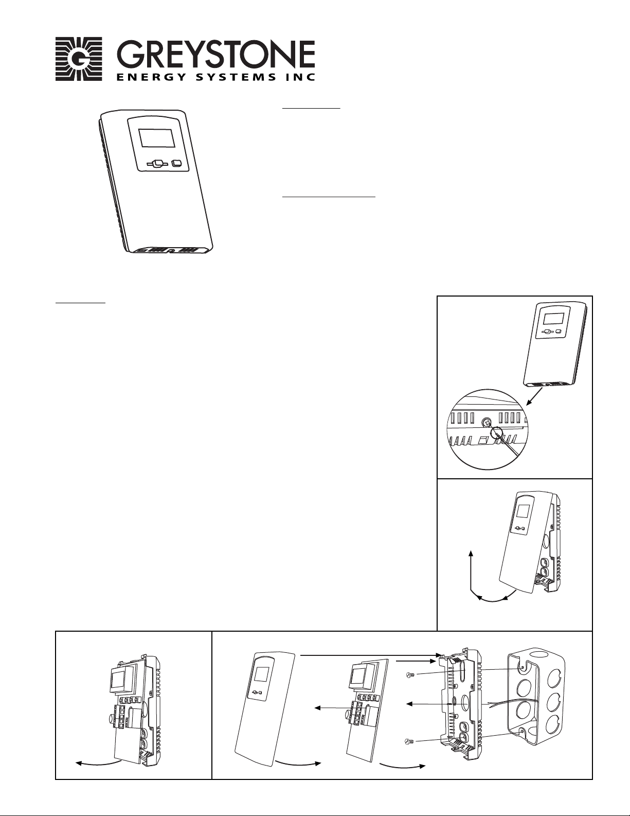
The cover is hooked to the base at the top edge and must be removed from the bottom
edge rst. Use a small Phillips screwdriver to loosen the security screw as shown in
Figure 1. (Complete removal of this screw is not required). Use the screwdriver to
carefully pry each bottom corner if necessary. Tip the cover away from the base and sit it
aside as shown in Figure 2.
The PCB must be removed from the base to access the mounting holes. Follow usual
anti-static procedures when handling the PCB and be careful not to touch the sensors.
The PCB is removed by pressing the enclosure base to unsnap the latch near the bottom
edge, then the PCB can be lifted out of the base as shown in Figure 3.
Sit the PCB aside until the base is mounted on the wall. For added protection, place
the PCB in the supplied anti-static bag.
Mount the base by screwing to an electrical box or directly to the wall as shown in
Figure 4. The mounting hole locations are shown on page 3.
After the base is screwed to an electrical box or the wall using the appropriate holes,
remove the PCB from the anti-static bag, feed connection wires through center hole and
place the top of PCB into the PCB holders on backplate and snap bottom of PCB into
place as shown in Figure 4.
Make wire connections as per the Wiring Illustrations on Page 2 and install decorative
cover by placing the top of the cover into the cover holder on the top of the backplate
and snapping the bottom into place as shown in Figure 4. Tighten security screw with
a Phillips screwdriver.
Figure 1
Figure 2
Figure 3
Greystone Energy Systems, Inc. 150 English Drive, Moncton, NB E1E 4G7 Canada Tel: +1-506-853-3057 Tollfree (North America): +1-800-561-5611 Fax: +1-506-853-6014
Figure 4
Cover PCB Backplate
Email: support@greystoneenergy.com Web: www.greystoneenergy.com
Wiring
Deactivate the 24 Vac/dc power supply until all connections are made to the device
to prevent electrical shock or equipment damage. Follow proper electrostatic
discharge (ESD) handling procedures when installing the device or equipment
damage may occur.
Use 22 AWG shielded wiring for all connections and do not locate the device wires in
the same conduit with wiring used to supply inductive loads such as motors.
Connect the cable shield to ground at the controller only. Make all connections in
accordance with national and local codes.
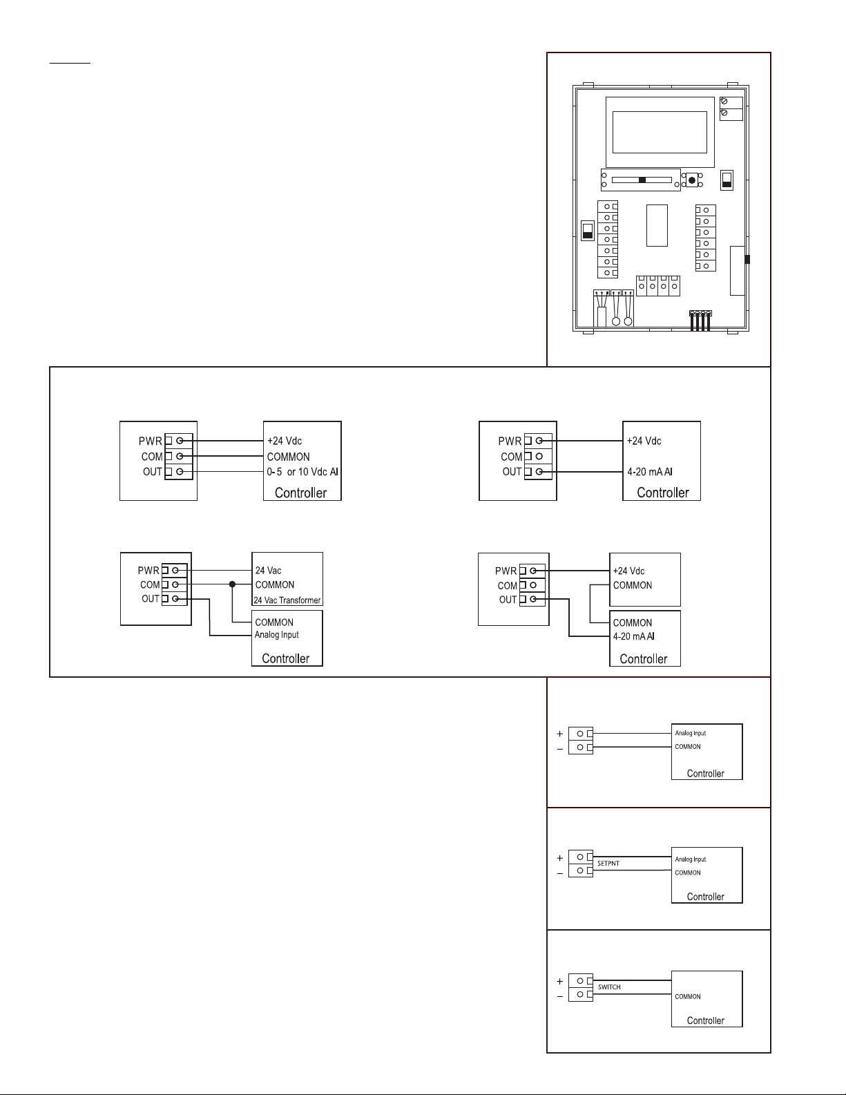
Connector layout is shown in Figure 5. Diagram shown includes all options. If option
is not ordered, connector will not be present.
For 4-20 mA two-wire loop-powered operation, only the POWER and OUTPUT
terminals are required if a DC power supply is used. The COMMON terminal is only
used for AC power or for a voltage output signal type. If the signal type is set to
voltage, or a 24 volt AC power supply is used, connect the positive dc voltage or the
hot side of the ac voltage to the terminal marked POWER and the power supply
common is connected to the terminal marked COMMON. The device is reverse
voltage protected and will not operate if connected backwards.
Figure 6
Wiring for voltage output signal
and 24 Vdc power from controller
Wiring for 4-20 mA loop-powered output and
external 24 Vdc power from controller
Figure 5
mA
Vdc
SETPNT +
SETPNT -
POWER
COMMON
OUTPUT
TEMP +
TEMP -
ZERO
SPAN
5v
OVERRIDE
LED +
LED -
SWITCH +
SWITCH -
FAN +
FAN -
4
123
10v
41 2 3
0001297
Wiring for all output signals and
external 24 Vac power transformer
Wiring for 4-20 mA loop-powered output and
external 24 Vdc external power supply
For three-wire voltage output operation, connect either an AC or DC power supply to
POWER and COMMON and the voltage output signal is available on the OUTPUT
terminal with respect to COMMON as shown in Figure 6.
Ensure the controller Analog Input (AI) matches the transmitter output signal type
before power is applied and that the pcb switches are set correctly for the required
signal type. The current signal has a maximum load that it will drive and the voltage
signal has a minimum load rating. Follow the ratings in the Specication section or
inaccurate readings may result.
This device has a half-wave power supply so the power supply common is the same
as the signal common. Several devices may be connected to one power supply and
the output signals all share the same common. Use caution when grounding the
secondary of a transformer or when wiring multiple devices to ensure the ground
point is the same on all devices and the controller.
The following optional features are only included if ordered. Wiring terminals are
only present for features ordered.
An optional resistive temperature sensor may also be included in the device and is
connected to the TEMP terminals as shown in Figure 7.
24 Vdc Power Supply
Figure 7
TEMP
Figure 8
Figure 9
Digital Input
Greystone Energy Systems, Inc. 150 English Drive, Moncton, NB E1E 4G7 Canada Tel: +1-506-853-3057 Tollfree (North America): +1-800-561-5611 Fax: +1-506-853-6014
Email: support@greystoneenergy.com Web: www.greystoneenergy.com
 Loading...