

Page 1
Introduction
The TTLSO single point strap-on temperature thermostat incorporates a
precision thermistor temperature sensor and provides a Form C relay output
(NO/NC) with an adjustable setpoint. The sensor is encapsulated to a 38 mm x 38
mm (1.5”x 1.5”) aluminum plate and adhered to a 38 mm x 25.4 mm (1.5 x 1“)
compressible foam. A 254 mm (10”) S/S Pipe clamp is provided to secure the
assembly to various sizes of pipe. All probes are constructed to provide excellent
heat transfer, fast response and are potted to resist moisture penetration.
Before Installation
Read these instructions carefully before installing and commissioning the
temperature thermostat. Failure to follow these instructions may result in
product damage. Do not use in an explosive or hazardous environment, with
combustible or ammable gases, as a safety or emergency stop device or in
any other application where failure of the product could result in personal
injury. Take electrostatic discharge precautions during installation and do
not exceed the device ratings.
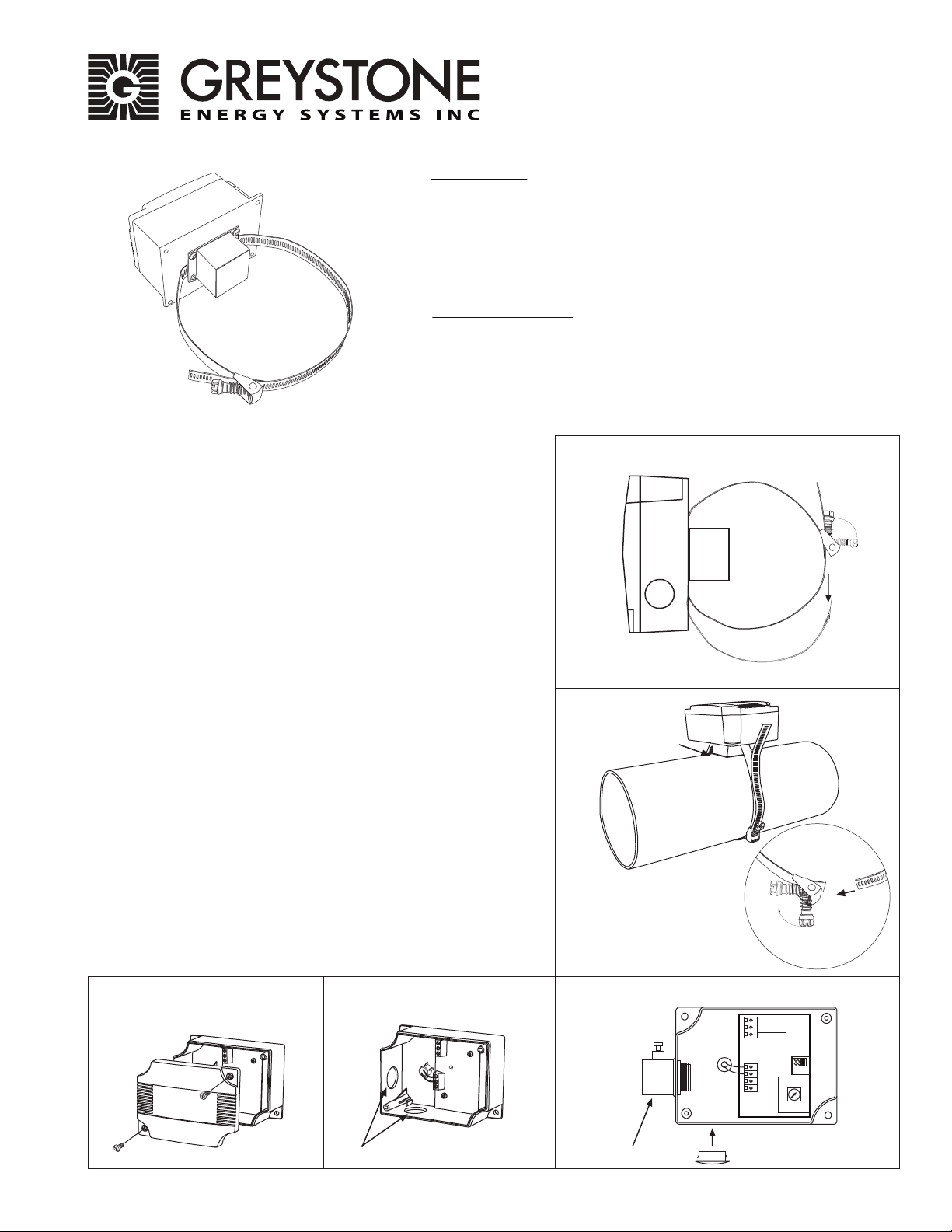
Mounting (Enclosure A)
The strap-on sensor installs directly onto any pipe where an immersion
sensor with thermowell can’t be installed.
Once a suitable spot is selected, remove a small block of insulation if
present. It is recommended that thermal compound be used to improve
heat transfer. Spread a liberal about on the pipe.
Strap-on
Temperature Thermostat
TTLSO Series
Installation Instructions
Figure 1
Open the worm gear clamp by swiveling the worm gear away from the
clamp and pull the clamp apart, as shown in Figure 1.
Place the sensor plate on the selected mounting area and wrap clamp
around the pipe. Re-insert clamp under the worm gear and pull until snug.
Lock in place by swiveling the worm gear towards the clamp. Tighten
worm gear clamp by using a standard screw driver or hex nut driver as
shown in Figure 2.
Using a Phillips screwdriver, remove the (2) screws, as shown in Figure 3.
Remove cover and set aside with screws for re-installing after wiring and
set up.
Two 21 mm (0.8125”) holes are provided for connection of either 12.77mm
(0.5” ) EMT or a cable gland style connector as shown in Figure 4. Insert the
EMT or cable gland connector through the hole and securely fasten using a
locknut. If only one connection hole is required, use the included hole cap
to cap o the unused one as shown in Figure 5. Special care must be
taken not to damage any internal components during installation.
Make wire connections as per the “Wiring” illustrations on Page 2.
Once wiring and set up are complete, re-install cover and tighten the (2)
screws using a Phillips screwdriver.
Figure 3 Figure 5Figure 4
Figure 2
Thermal Compound
DIFFERENTIAL
TEMP PWRCOM NCNO COM
EMT/Cable Gland Connection Holes
Greystone Energy Systems, Inc. 150 English Drive, Moncton, NB E1E 4G7 Canada Tel: +1-506-853-3057 Tollfree (North America): +1-800-561-5611 Fax: +1-506-853-6014
Email: support@greystoneenergy.com Web: www.greystoneenergy.com
EMT Connector
Connection Hole Cap
HIGH
LOW
MID
Page 2
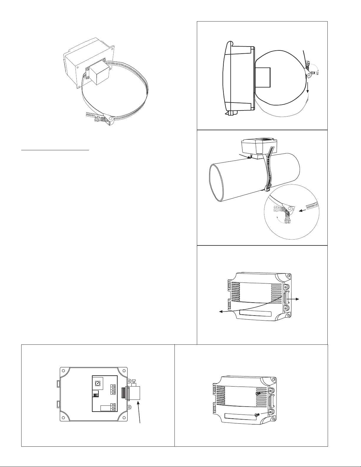
Figure 6
Figure 7
Mounting (Enclosure D)
The strap-on sensor installs directly onto any pipe where an immersion
sensor with thermowell can’t be installed.
Once a suitable spot is selected, remove a small block of insulation, if
present. It is recommended that thermal compound be used to
improve heat transfer. Spread a liberal about on the pipe.
Open the worm gear clamp by swiveling the worm gear away from the
clamp and pull the clamp apart, as shown in Figure 1.
Place the sensor plate on the selected mounting area and wrap clamp
around the pipe. Re-insert clamp under the worm gear and pull until
snug. Lock in place by swiveling the worm gear towards the clamp.
Tighten worm gear clamp by using a standard screw driver or hex nut
driver as shown in Figure 2.
The enclosure has a hinged cover with latch. Open cover by pulling
slightly on the latch on the right side of the enclosure. At the same time
pulling on the cover, as illustrated in Figure 8.
Feed conduit through the provided hole in bottom of enclosure and
secure with a lock nut as show in Figure 9. It is recommended that
weatherproof conduit or cable gland ttings be used.
Make wiring connections as per the “Wiring” illustrations on Page 2.
Swing door closed until securely latched. For added security, 2 screws
are provided that may be installed in the integrated screw tabs. See
Figure 10.
Thermal Compouind
Figure 8
Figure 9
MID
LOW
HIGH
DIFFERENTIAL
Greystone Energy Systems, Inc. 150 English Drive, Moncton, NB E1E 4G7 Canada Tel: +1-506-853-3057 Tollfree (North America): +1-800-561-5611 Fax: +1-506-853-6014
TEMP PWRCOM NCNO COM
EMT Connector
Email: support@greystoneenergy.com Web: www.greystoneenergy.com
Figure 10
Page 3

Wiring
• Deactivate the 24 Vac/dc power supply until all connections are made to the device to prevent electrical shock or
equipment damage.
• Use 14-22 AWG shielded wiring for all connections and do not locate the device wires in the same conduit with
wiring used to supply inductive loads such as motors. Make all connections in accordance with national and local
codes.
• The temperature thermostat comes with the temperature sensor pre-wired to the PCB. If removal is required for
installation then it may be re-wired as shown in Figure 11.
• Pull at least six inches of control wire into the enclosure, then complete the wiring connection according to the
wire diagram for the applicable power supply as shown in Figure 12.
• Connect the DC positive or the AC voltage hot side to the PWR terminal. The supply common is connected to the
COM terminal. See Figure 12.
•The relay has both Normally Open (NO) and Normally Closed (NC) contacts available. The relay output is available
on the NO/COM/NC terminal. Make connections before applying power as shown in Figure 13.
• The setpoint dierential has 3 jumper selectable settings (Low/Mid/High) Set jumper to desired dierential as
shown in Figure 14.
• To set the switching setpoint, turn the setpoint potentiometer to the desired temperature setting as shown in
Figure 15.
• Once all connections settings are made and checked, power can be applied.
Figure 11
Temperature sensor wiring to PCB
(Factory Wired)
TEMP
Figure 12
Power Supply Wiring
No Polarity
Temperature
Sensor
DIFFERENTIAL
TEMP PWRCOM NCNO COM
HIGH
LOW
MID
Figure 13
Relay Output Wiring
NO
NC
NO
NC
24 Vdc Power Supply
Digital
Input
Figure 14 Figure 15
24 Vdc Power Supply
Setpoint Adjustment
SETPOINT
Specication:
Power Supply.......................12 to 28 Vac/dc
Consumption.......................50 mA max
Relay Contacts.....................SPDT, Form C contacts (N.O. and N.C.)
5 Amps @ 30 Vdc/250 Vac resistive
1.5 Amps @ 30 Vdc/250 Vac inductive
Relay Action..........................Activates on temperature fall
Setpoint Operation............Single-turn knob-pot on pcb
Adjustable Setpoint...........-4 to 10˚C (25 to 50˚F)
Setpoint Temperature ...... Low/Mid/High jumper selectable
Dierential 1.1/2.8/5.6 °C (2/5/10 ˚F)
Temperature Sensor..........10K ohm curve matched
precision thermistor
Sensor Accuracy..................±0.2˚C, 0 to 70˚C (±0.36˚F, 32 to 158˚F)
Probe Sensing Range ....... .-20 to 105 ˚C (-4 to 221 ˚F)
Probe Material ....................Aluminum plate
w/ compressible foam backing
Probe Diameter......... ..........38 mm (1.5”) square
Wire Material........................ PVC insulated, parallel bonded
Operating Conditions.......-10 to 50˚C (14 to 122˚F),
5 to 95% RH non-condensing
Storage Conditions............-30 to 70˚C (-22 to 158˚F),
5 to 95%RH, non-condensing
Enclosure............................... (A) ABS, UL94-5VB, IP61 (NEMA 2)
(D)-ABS, UL94-5VB, IP65 (NEMA 4X)
Wiring Connections...........Screw terminal block
(14 to 22 AWG)
Setpoint Dierential Setting
DIFFERENTIAL
HIGH
MID
LOW
HIGH - 5.6C/10F
MID = 2.8C/5F
LOW = 1.1C/2F
Greystone Energy Systems, Inc. 150 English Drive, Moncton, NB E1E 4G7 Canada Tel: +1-506-853-3057 Tollfree (North America): +1-800-561-5611 Fax: +1-506-853-6014
Email: support@greystoneenergy.com Web: www.greystoneenergy.com
Page 4

Dimensions:
Enclosure A
53.6 mm
2.110 “
Compressible Foam
Quick release
115.8 mm
4.56 “
Enclosure D
145 mm
5.7 “
64 mm
2.5 “
1.125 “
28.58 mm
2X Ø 0.850”
28.58 mm
1.125 “
38.1 mm (1.5”)
Aluminum Plate
Compressible Foam
38.1 mm (1.5” )
Aluminum Plate
254 mm (10”)
S/S Pipe Clamp
Quick release
114.3 mm
4.5 “
84.3 mm
3.320 “
88.9 mm
3.5 “
100 mm
3.95 “
Ø 0.850”
10”S/S Pipe
Clamp
TTLSO-INS-001 06/16
Greystone Energy Systems, Inc. 150 English Drive, Moncton, NB E1E 4G7 Canada Tel: +1-506-853-3057 Tollfree (North America): +1-800-561-5611 Fax: +1-506-853-6014
Email: support@greystoneenergy.com Web: www.greystoneenergy.com
PRINTED IN CANADA Copyright © Greystone Energy Systems Inc. All Rights Reserved
 Loading...