

Page 1
RH200A RH Transmitter
Installation Instructions
Introduction
This humidity transmitter uses a highly accurate and reliable Thermoset
Polymer based capacitance humidity sensor and state-of-the-art digital
linearization and temperature compensated circuitry to monitor
humidity levels in a duct. The humidity sensor is encapsulated in a 60
micron HDPE lter at the end of a 230 mm (9”) S/S probe and a compact
enclosure. An optional temperature sensor is available.
Before Installation
Read these instructions carefully before installing and commissioning
the RH transmitter. Failure to follow these instructions may result in
product damage. Do not use in an explosive or hazardous environment,
with combustible or ammable gases, as a safety or emergency stop
device or in any other application where failure of the product could
result in personal injury. Take electrostatic discharge precautions
during installation and do not exceed the device ratings.
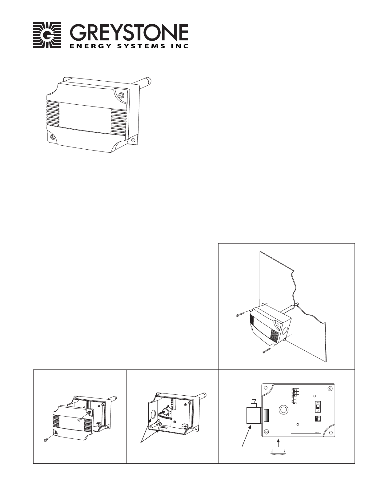
Mounting
The tranmitter installs directly into any air duct with a minimum width/diameter of 25.5 cm (10”). Select a suitable installation
area in the middle of the duct wall. To achieve the best reading, do not place in an area where air stratication may be
present. Mount the sensor at least 1.5 m (5 ‘ ) in either direction from elbows, dampers, lters or other duct restric-
tions. Avoid areas where the transmitter is exposed to vibrations or rapid temperature changes.
Once a suitable spot is selected, drill a 15 -20 mm (0.6” - .75“ ) hole for the probe.
Slide the probe in the drilled hole until the enclosure is ush against the duct. The airow direction is not important. Secure
the enclosure to the duct with (2) #10 x 1” (25 mm) self tapping screws (Not provided). Tighten screws until the enclosure is
tight against the duct and that there is no movement of the enclosure as shown in Figure 1.
A foam gasket is provided on the back of the enclosure that provides a
tight seal against any air leaks.
Using a Phillips screwdriver, remove the (2) screws, as shown in Figure 2.
Remove cover and set aside with screws for re-installing after wiring
and set up.
Two 21 mm (0.8125”) holes are provided for connection of either
12.77mm (0.5” ) EMT or a cable gland style connector as shown in Figure 3.
Insert the EMT or cable gland connector through the hole and securely
fasten using a locknut. If only one connection hole is required, use the
included hole cap to cap o the unused one as shown in Figure 4.
Special care must be taken not to damage any internal components
during installation.
Make wire connections as per the “Wiring” illustrations on Page 2.
Once wiring and set up are complete, re-install cover and tighten the (2)
screws using a Phillips screwdriver.
Figure 2 Figure 4Figure 3
Figure 1
Greystone Energy Systems, Inc. 150 English Drive, Moncton, NB E1E 4G7 Canada Tel: +1-506-853-3057 Tollfree (North America): +1-800-561-5611 Fax: +1-506-853-6014
EMT/Cable Gland Connection Holes
Email: support@greystoneenergy.com Web: www.greystoneenergy.com
EMT Connector
Connection Hole Cap
Page 2
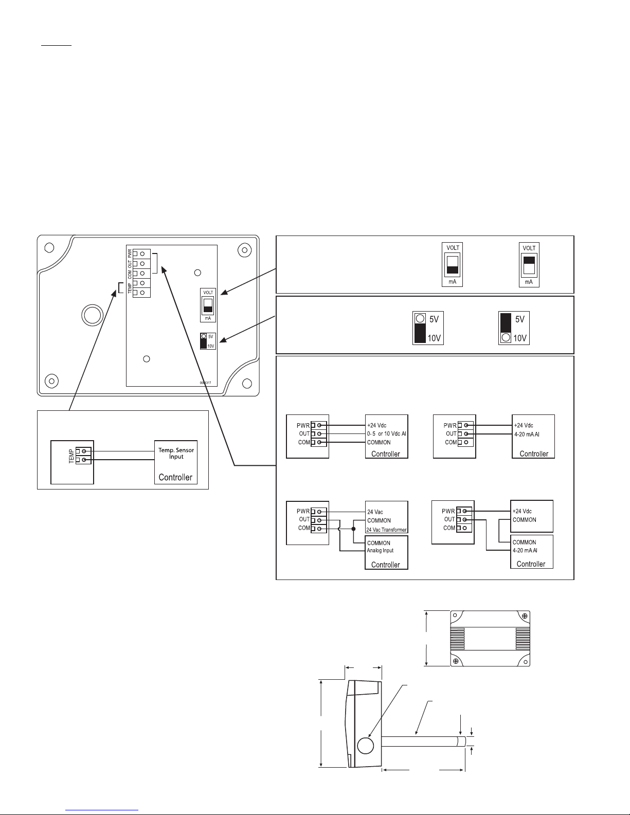
Wiring
• Deactivate the 24 Vac/dc power supply until all connections are made to the device to prevent electrical shock or equipment
damage.
• Use 14-22 AWG shielded wiring for all connections and do not locate the device wires in the same conduit with wiring used
to supply inductive loads such as motors. Make all connections in accordance with national and local codes.
• Pull at least six inches of wire into the enclosure, then complete the wiring connection according to the wire diagram for the
applicable power supply and output signal type.
• Select desired signal output type (mA or Vdc) by placing the output switch in required position, as shown in Figure 5.
Factory default is mA (4-20 mA).
• If mA was selected, no further Output set up is required. If VOLT output is selected in Figure 5, place Voltage Output Jumper
to desired span position, as shown in Figure 6. ie: 10 = 0-10 Vdc. Factory default is 10v = 0-10Vdc.
• Connect the DC positive or the AC voltage hot side to the PWR terminal. For voltage output or AC power, the supply
Common is connected to the COM terminal. The device is reverse voltage protected and will not operate if connected
backwards. It has a half-wave power supply so the supply Common is the same as the signal Common. See Figure 7.
•The analog output is available on the OUT terminal. Check the controller Analog Input to determine the proper
connection before applying power as shown in Figure 7.
• If installed, the resistance temperature output is available on the two terminals labelled TEMPERATURE SENSORas shown in
See Figure 8.
Figure 5
Output Type
Selection Switch
mA = 4-20 mA
(Factory Default)
VOLT = Vdc
Figure 8
Optional Temperature Sensor
Specication:
Sensor Type:...................Thermoset Polymer based Capactive
Range:..............................0 to 100% RH
Accuracy:........................±2, 3, or 5% RH (5 to 95% RH)
Response:.......................15 Seconds typical
Temp Dependence:....±0.05% RH/ ˚C
Hysteresis:......................±1.5% RH maximum
Repeatability:...............±0.5% RH typical
Linearity:........................±0.5% RH typical
Operating Range:........-40 to 85˚C (-40 to 185˚F)
Power Supply:...............18 to 30 Vdc, 15 to 26 Vac
Consumption:...............22 mA maximum
Protection Circuitry:...Reverse voltage protected and output
limited
Output Signal:..............4-20 mA current loop, 0-5 or 0-10 Vdc
(selectable)
Output Drive @ 24 Vdc:..550 ohms max for current output
10K ohms min for voltage output
Internal Adjustments:.Clearly marked ZERO and SPAN pots
Optional Temp.:............RTD’s or Thermistors. 2 Wire
Probe:..............................230 mm (9”) probe length x 12.7 mm (1/2”)
diameter stainless steel with 60 micron HDPE
porous lter
Enclosure:......................ABS - UL94-5VB - IP61 (NEMA 2)
*In order to maintain the published NEMA/IP
ratings, properly rated conduit or cable gland
adapters must be used.
Termination:.................Screw terminal block (14 to 22 AWG)
Greystone Energy Systems, Inc. 150 English Drive, Moncton, NB E1E 4G7 Canada Tel: +1-506-853-3057 Tollfree (North America): +1-800-561-5611 Fax: +1-506-853-6014
Email: support@greystoneenergy.com Web: www.greystoneenergy.com
Figure 6
Voltage
Output
Selection
* No setting required if output selection switch is set to mA in Figure 5
0-10 Vdc
(Factory
default)
Figure 7
Wiring for voltage output signal
and 24 Vdc power from controller
Wiring for all output signals and
external 24 Vac power transformer
Dimensions:
53.6 mm
2.110 “
115.8 mm
4.56 “
0-5 Vdc
Wiring for 4-20 mA loop-powered
output and external 24 Vdc power
from controller
Wiring for 4-20 mA loop-powered
output and external 24 Vdc external
power supply
24 Vdc Power Supply
84.3 mm
3.320 “
2X Ø 0.850”
304 Series S/S Probe
60 micron HDPE lter
12.70 mm
0.50“
228.60 mm
9”
V. RH200A 10/14
Copyright © Greystone Energy Systems Inc. All Rights Reserved
PRINTED IN CANADA
 Loading...