

Page 1
Application
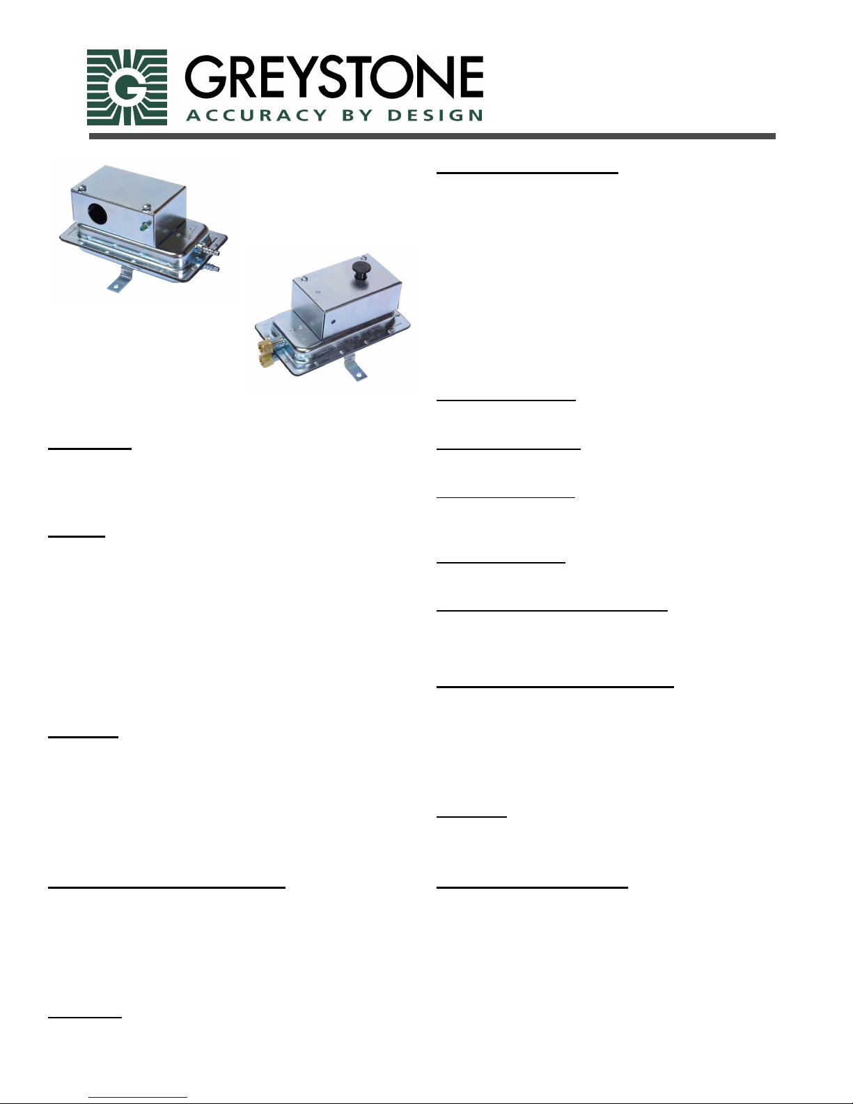
The AFS is a general purpose airflow proving switch designed
for HVAC and energy management applications. It may be
used to sense positive, negative or differential air pressure.
General
The plated housing contains a diaphragm, a calibration spring
and a snap-acting SPST (NC) switch.
The sample connections located on each side of the diaphragm
accept a .25” OD tubing via the integral compression and nut or
barbed fitting.
An enclosure cover guards against accidental contact with the
live switch terminal screws and the set point adjusting screw.
The enclosure cover will accept a .5” conduit connection. The
AFS-460 has a reset button located on the top surface of the
enclosure cover.
Mounting
Select a mounting location which is free from vibration. The
AFS pressure switch MUST be mounted with the diaphragm in
any vertical plane in order to obtain the lowest specified
operating set point. Avoid mounting with the sample line
connections in the “UP” position. Surface mount via the two
3/16” diameter holes in the integral mounting bracket. The
mounting holes are 3 7/8” apart.
Air Flow Switch
Installation Instructions
Air Sampling Connection
The AFS is designed to accept firm-wall sample lines of .25"
OD tubing by means of ferrule and nut compression connections. For sample lines of up to 10 feet, .25" OD tubing is acceptable. For lines up to 20 feet, use .25" ID tubing. For lines up
to 60 feet, use .5" ID tubing. A .25" OD adapter, suitable for
slip-on flexible tubing is available: order part number 18311.
Locate the sampling probe a minimum of 1.5 duct diameters
downstream from the air source. Install the sampling probe as
close to the center of the airstream as possible. Identify the high
pressure inlet (H) and the low pressure inlet (L). Select one of
the five application options listed below and connect the sample
lines as recommended.
Positive Pressure Only:
Connect the sample line to inlet H;
inlet L remains open to the atmosphere.
Negative Pressure Only:
Connect the sample line to inlet L;
inlet H remains open to the atmosphere.
Two Negative Samples:
Connect the higher negative sample
to inlet L. Connect the lower negative
sample to inlet H.
Two Positive Samples
Connect the higher positive sample to inlet
H. Connect the lower positive sample to inlet L.
One Positive and One Negative Sample
Connect the positive sample to inlet H. Connect the negative
sample to inlet L.
Field Adjustment-AFS-262 (-112)
The adjustment range of an AFS-262 Air Switch is 0.05 ±.02"
w.c. to 2.0" w.c. To adjust the set point, t urn the adjusting
screw counterclockwise until motion has stopped.
Next, turn the adjusting screw 4 complete turns in a clockwise
direction to engage the spring. From this point, the next ten
turns will be used for the actual calibration.
Each full turn represents approximately 0.2" w.c.
Please note: To properly calibrate an air switch, a digital
manometer or other measuring device should be used to
confirm the actual set point.
Field Adjustment-AFS-222 (-112)
The adjustment range of an AFS-222 Air Switch is 0.05 ±.02"
w.c. to 12.0" w.c. To adjust the set point, t urn the adjusting
screw counterclockwise until motion has stopped.
Next, turn the adjusting screw 4 complete turns in a clockwise
direction to engage the spring. From this point, the next ten
turns will be used for the actual calibration.
Each full turn represents approximately 1.2" w.c.
Please note: To properly calibrate an air switch, a digital
manometer or other measuring device should be used to
confirm the actual set point.
Field Adjustment-AFS-460
The adjustment range of an AFS-460 Air Switch is 0.4" ± 0.02"
w.c. to 12.0" w.c. To adjust the set point, turn the adjusting
screw counterclockwise until motion has stopped.
Next, turn the adjusting screw four complete turns in a
clockwise direction to engage the spring. From this point, the
next ten turns will be used for the actual calibration.
Each full turn represents approximately 1.16" w.c.
Please note: To properly calibrate an air switch, a digital
manometer or othermeasuring device should be used to confirm
the actual set point.
Page 2
Specifications
MODEL
SAMPLE MEDIA
MOUNTING POSITION
FIELD ADJUSTABLE RANGE
SWITCH DIFFERENTIAL
MAXIMUM PRESSURE
OPERATING TEMPERATURE RANGE
LIFE
ELECTRICAL RATING
CONTACT ARRANGEMENT
ELECTRICAL CONNECTIONS
SAMPLE LINE CONNECTIONS
AUTOMATIC/MANUAL RESET
AFS-222/AFS-222-112 AFS-262/AFS-262-112 AFS-460
Air Air Air
Diaphragm in any vertical plane Diaphragm in any vertical plane Diaphragm in any vertical plane
.05, ±.02” w.c. to 12” w.c. .05, ±.02” w.c. to 2” w.c. .40, ±.06” w.c. to 12” w.c.
Progressive, increasing from
approximately .02± .01” w.c. at
minimum set point to approximately
0.8” w.c. at maximum set point.
.5” (0.03 bar) .5” (0.03 bar) .5” (0.03 bar)
-40°C – 82.2°C (-40°F–180°F) -40°C – 82.2°C (-40°F–180°F) -40°C – 82.2°C (-40°F–180°F)
100,000 cycles/min. at 5psi max
pressure each cycle and at max
electrical load.
300 va pilot duty at 115-277vac, 10
amp, non-inductive, 277 vac, 60Hz.
SPDT SPDT SPDT
Screw top terminals with cup washers
Ferrule and nut compression type
connectors that accept 6.35 mm
(.25”) OD rigid tubing or 1/4“
barbed fittings (-112) that accept
flexible tubing.
Automatic Automatic Manual
Progressive, increasing from
approximately 0.02± 0.01” w.c. at
minimum set point to approximately
0.1” w.c. at maximum set point.
100,000 cycles/min. at 5psi max
pressure each cycle and at max
electrical load.
300 va pilot duty at 115-277vac, 10
amp, non-inductive, 277 vac, 60Hz.
Screw top terminals with cup
washers
Ferrule and nut compression type
connectors that accept 6.35 mm
(.25”) OD rigid tubing or 1/4“
barbed fittings (-112) that accept
flexible tubing.
Progressive, increasing from
approximately .06± .01” w.c. at
minimum set point, to
approximately .8”w.c. at maximum
set point.
600 cycles/min. at 5psi max pressure each cycle and at max electrical
load.
300 va pilot duty at 115-277vac, 10
amp, non-inductive, 277 vac, 60Hz.
Screw top terminals with cup
washers
Ferrule and nut compression type
connectors that accept 6.35 mm
(.25”) OD rigid tubing.
APPROVALS
UL and CSA UL and CSA UL and CSA
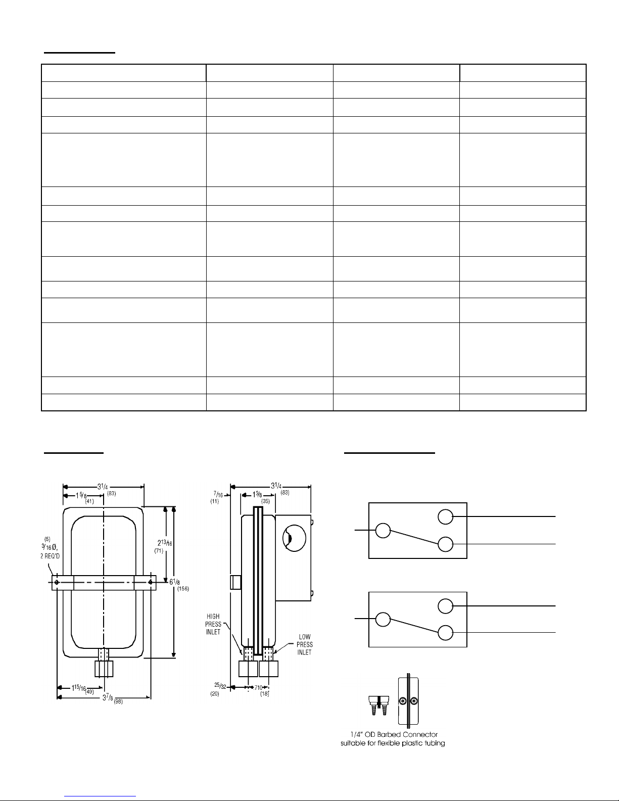
Dimensions Alarm or Control
To prove excessive airflow or pressure
C
NO
NC
To prove insufficient airflow or pressure
C
NO
NC
Alarm
Control
Control
Alarm
01/07/09
 Loading...