

Page 1

ENGLISH
READ
BEFORE
FIRST
RIDE
Page 2
WWW.GREYP.COM
Page 3
BIKE USER MANUAL
ENGLISH
Page 4
Contents
INTRODUCTION 5
Greyp bikes disclaimer 5
BIKE
General information 5
Safety information 6
General information
about assembly 7
GENERAL NOTES
ABOUT RIDING
Riding tips 8
Pre-ride Inspection 9
Children ridding 9
Seat post – basics 9
Brake levers – basics 10
Suspension – basics 11
Rear Suspension 11
Adjusting rebound 11
Adjusting compression 12
Adjusting threshold 12
Adjusting lockout 12
Front suspension 13
Shock pressure chart 13
Recommended tire pressure 13
Assembling parts supplied
unassembled 14
8
BATTERY AND CHARGER 16
Battery technical data 16
Important battery information 17
Charging process 18
First start-up
and charging 19
SYSTEM FUNCTIONS 20
Bike parts 20
Control unit functions 21
Display unit
information 22
Power on 23
Stand by mode on 23
Stand by mode off 23
Power off 24
Walk assist mode 24
Lights on/off 24
Joystick 25
Assist level up/down 25
Battery Pack mount/dismount 26
BIKE USAGE 27
Maintenance 27
Range 29
Page 5

Shifting recommendations 29
Recommended tightening
of fasteners 30
CLEANING THE BIKE 33
Chain 33
Fork 33
Shock 33
Lubrication 33
WARRANTY 34
General 34
Battery 35
Frame 36
Motor 36
Electronics 36
Brakes 36
Suspension 36
Drivetrain 37
How to le a claim 37
INTRODUCTION 43
Onboarding 43
Connect to GVC 43
Forgotten password 43
APPLICATION
Bike pairing 44
REMOTE CONTROL 46
Remote control section 46
Notications section 47
Activity section 48
Settings section 49
DASHBOARD 50
Fitness Session 51
Camera 52
Retro video 53
Potato 53
Navigation 54
SOFTWARE UPDATE 55
DISPOSAL 38
Only for EC countries: 38
EC – DECLARATION
OF CONFORMITY 39
Greyp G6 mobile application is available
on Google PlayStore
Page 6

Page 7
Introduction
This user manual is specic to your Greyp G6 vehicle. It contains important safety, performance and technical information, which you should read before your rst ride and keep for
reference. You should also read the entire User Manual, because it has additional important
general information and instructions that you should follow.
If you do not have a copy of the User Manual, you can download it for free
at www.greyp.com or obtain it from your nearest Authorised Greyp Retailer.
Greyp Bikes Disclaimer
Any modications of the bike are strictly forbidden and Greyp Bikes d.o.o. will bear no liability
whatsoever for the consequences of such modications. Greyp Bikes d.o.o. does not grant,
explicitly or implicitly, to any party any patent rights, licenses or any other IP rights, whether with regard to such information itself or to anything described by such information. The
information provided by Greyp Bikes d.o.o. hereunder is provided “as is, where is” and with
all faults, and the entire risk associated with such information is entirely with the Buyer. The
information provided in this document is proprietary to Greyp Bikes d.o.o., and Greyp Bikes
d.o.o. reserves the right to make any changes to the information in this document or to any
products and services at any time without notice.
You should check www.greyp.com for any changes made in the user manual.
Greyp Bikes d.o.o.,
Ljubljanska 7, 10431 Sveta Nedelja, Croatia,
13th of May 2019.
General information
Important notice: Please make sure you read this manual before operating a Greyp bike for
the rst time. It is very important to follow the instructions in the manual to make sure, you
use Greyp in the proper way. Greyp Bikes d.o.o. reserves the right to change the design, com-
INTRODUCTION
5
Page 8
ponents, and specications at any time without notice and without any obligation. The illustrations and pictures in this manual are for demonstration purposes only.
Important notice: Please contact your dealer or manufacturer before trying to repair your
Greyp. This manual is not intended as a service and repair manual.
The Greyp G6 is classied as a Pedelec. The G6 is a vehicle where the rider’s pedalling is assisted
by an electric motor with 5 assist and torque levels, which gives you a range of power assistance.
Motor support will automatically switch off when you reach a maximum speed of 25km/h for
model G 6.1. and G 6.2 and 45 km/h for model G 6.3. A driver’s license or insurance is typically not
required. Regardless of its classication, it will only provide motor support only while pedalling.
Before using your Greyp vehicle, please inform yourself of all applicable legal requirements
and regulations in your country or state. There may be restrictions on riding your Greyp on
public roads, cycling paths, and/or trails. There may also be applicable helmet requirements,
age restrictions or license or insurance requirements. As laws and regulations regarding electric vehicles vary by country and or state and are constantly changing, please make sure you
obtain the latest information. You should also regularly see your Authorized Greyp Retailer for
updated information.
All Greyp G6 vehicles have a xed pre-set speed limit at which the motor support will automatically shut off. Any (attempted) tampering with the power output and/orsystem (i.e. excluding the exchange of sprocket with non-original parts) is prohibited, will void the warranty,
is extremely dangerous and could result in severe and/or fatal injuries.
Safety information
Please carefully read all the warnings and notes in this user manual before using your Greyp.
WARNING — As with all mechanical components, the EPAC is subjected to wear and high
stresses. Different materials and components may react to wear or stress fatigue in different
ways. If the design life of a component has been exceeded, it may suddenly fail, possibly causing injuries to the rider. Any form of crack, scratches or change of colouring in highly stressed
areas indicate that the lifespan of the component has been exceeded and it should be replaced.
WARNING — For composite components, impact damage may be invisible to the user; the
manufacturer shall explain the consequences of impact damage and that in the event of an
impact, composite components should either be returned to the manufacturer for inspection
or destroyed and replaced.
The A-weighted emission sound pressure level at the driver’s ears is less than 70 dB(A)
Inappropriate handling of Greyp products can cause damage, injury and/or death. Please
make sure you learn how to operate the Greyp in a safe and responsible way.
The Greyp G6 is intended to transport for one person at a time. If you allow somebody else to
use your Greyp, please provide them with this user manual.
We advise keeping the original box that the bike came with for the warranty period in case
there are any troubles.
INTRODUCTION
6
Page 9

We strongly advise you to wear a helmet and other safety equipment while riding the Greyp.
In some countries, there is an obligation to wear a helmet. Please check if this is the case in
your country.
Only ride at ambient temperatures between 5°C and 40°C.
Important notice: Greyp lights are primarily designed as auxiliary lights and you should take
care that you use lights that are according provision in force in the country of use.
General information about assembly
This user manual is not intended as a comprehensive use, service, repair or maintenance
guide. Please see your authorized Greyp Bikes partner for all service, repairs or maintenance.
Important notice: Do not alter or modify any parts of the Greyp. Do not install incompatible
components or hardware.
The maximum permissible total weight (vehicle + driver + luggage)
of Greyp G6 is 150kg.
VEHICLE THE PERMISSIBLE TOTAL PAYLOAD (DRIVER + LUGGAGE) VEHICLE WEIGHT
G6.1 125.5 KG 24.5 KG
G6.2 125 KG 25 KG
G6.3 126 KG 24 KG
You can nd additional safety, performance and service information for specic components
such as suspension, brakes or motor in the manufacture’s guidelines.
INTRODUCTION
7
Page 10

General notes about riding
The G6 motor provides pedal assistance while you are pedalling, and the vehicle is in motion.
The amount of pedal assistance will be higher or lower depending on the amount of force
applied to the pedals. If you stop pedalling, the motor will stop providing any assistance. The
G6 vehicle can also be ridden as a normal bicycle without motor assistance by switching the
vehicle to the OFF mode. The same applies if the battery is empty.
The G6 vehicle has a walk-assist mode (the motor engages without pedal force being applied)
which is designed to provide assistance when walking the vehicle up a hill.
Riding tips
Below are some riding tips, which may also reduce component
wear and increase battery range.
» Pay attention to your speed when going into a corner and be sure to
stop pedalling well before entering the corner. Otherwise you may
have too much speed as you enter the corner.
» Ride efciently and look ahead. Any time braking force is applied,
more energy is needed to get the vehicle back up to speed.
» Shift gears regularly to stay in an optimal cadence range and down-
shift before coming to a stop.
» Reduce pedal force before initiating a gear shift to reduce drivetrain
wear
» Check the tyre pressure regularly. Low pressure can cause the tires
to roll inefciently. If your vehicle is exposed to cooler weather, keep
the battery stored indoors until just before riding.
» Do not expose your vehicle to excessive heat.
» Only carry the cargo you need. More cargo weight requires more en-
ergy to move.
GENERAL NOTES ABOUT RIDING
8
Page 11
Pre-Ride Inspection
» Prior to the rst ride, charge the battery to 100%
» Check to ensure that the quick-release levers or axle nuts are tight
» Check the brake pads for excessive or uneven wear
» Make sure that all bolts on the brakes and steering parts are tight.
» Spin the rims – check for wobbles while sighting on the rims (make sure that the
rims do not rub on the brake pads)
» Check the tire pressure
» Check the tires for excessive wear, cracking or gashes
» Be certain that the handlebar and stem are tight
» Check that the gears shift smoothly
» Check the chain for rust, dirt, stiff links or noticeable signs of wear (the chain should
be clean and lubricated, be sure to use a chain-elongation gauge)
» Apply the front brake, and push the bike forward and backward (the headset should
be tight and not make any clunking noises)
Children riding
Greyp bikes are only designed and tested for use by one person at a time. Greyp bikes are not
intended for children below 16 years. Do not allow children under 16 years old to drive a Greyp.
Seat post – basics
Greyp G6 bikes have a telescopic seat post.
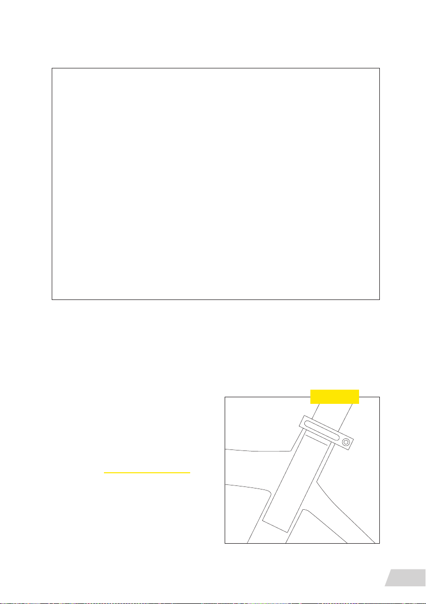
Familiarise yourself with the features of the
seat post before your rst ride. Only operate
the telescopic seat if it will not distract any of
your attention from the road and terrain. Refer
to information from the telescopic seat post
manufacturer (www.kssuspension.com). A telescopic seat post allows the saddle height to
be adjusted by operating a lever underneath the
saddle or a remote control on the handlebars,
both at a standstill and while ridding.
The saddle height is always measured with the
crank arm pointed down and in line with the
Seat post
MIN
INSERT
GENERAL NOTES ABOUT RIDING
9
Page 12

seat tube. The distance from the centre of the pedal axle to the top of your saddle is your
saddle height. Before changing the height of your saddle, you should measure your current
saddle height.
All seat post models must be inserted into the vehicle’s seat tube to cover the minimum insertion line indicated on the seat post. Insufcient insertion of the seat post into the vehicle
frame’s seat tube could result in damage to the seat post and/or vehicle and may result in a
loss of control of the vehicle, which may lead to serious injury or death.
To lower the saddle, weight the saddle rmly with your hand or sit on the bike while pressing
and holding the actuation lever or remote. Release the lever when the desired height is reached.
To raise the saddle, actuate your seat post by pulling the lever or handlebar remote. Unweight
the saddle and release the lever when the desired height is reached.
You can raise and lower your saddle to any desired position within the seat post’s travel.
Brake levers – basics
FORMULA braking devices are a high-performance product, offering a stopping power greater
than normal brakes. As a result, less effort is required to lock up the wheel when braking. Be
careful as a locked wheel can result in loss of control of the vehicle and can cause injuries.
Brakes are essential for the safe use of a vehicle. The improper setup and use of the brakes
can make you lose control and cause an accident, with unpredictable consequences and/or
potentially serious injuries. Disc brakes get VERY hot when used. The left lever operates the
front brake. The right lever operates the rear brake.
NEVER touch the calliper or the rotor immediately after use. Make sure the brakes have cooled
down before working on them.
The brake rotors must be installed on wheels that are suitable for this type of brake system.
A wheel with an insufcient spoke section or with radial spoke lacing can break under normal
use of the braking system and cause serious injury, accident or death. Check with your wheel
manufacturer BEFORE installation to ensure compatibility.
Check the spoke tension and condition frequently. A damaged spoke may break suddenly
and interfere with the braking system. This may result in serious personal injury, accidents
or death.
Before every ride, make sure there are no fluid leaks in the system by applying the lever and
holding it down as far as it will go. Check the hose connections and the brake fluid reservoir
for any leaks. Consult a professional mechanic if there are fluid leaks. A fluid leak can cause
a serious accident or death!
CAUTION: braking distances may be greater in wet weather.
Test the brakes and your braking technique on flat and even ground before using the bike in
more severe conditions.
You can nd more info about formula Cura brakes on www.rideformula.com
GENERAL NOTES ABOUT RIDING
10
Page 13
Suspension – basics
You must read and understand the Safety Instructions document included with your product
before proceeding with installation. Improperly installed components are extremely dangerous and could result in severe and/or fatal injuries. If you have any questions about the installation of these components, consult a qualied bicycle mechanic.
Rear Suspension
Suspension sag can be used to set the proper suspension spring rate for the rider. Sag is
the amount (percentage) the suspension compresses when the rider, including riding gear,
is seated on the vehicle in the riding position. Setting the proper sag allows the wheels to
maintain traction without using too much of the travel reserved for shock absorption. More
sag increases small bump sensitivity, while less sag decreases small bump sensitivity. Set the
spring sag before making any other tuning adjustments.
Pressurize the shock (PSI) to the equivalent of the rider’s total weight (lbs), including gear.
Example: 160 lbs = 160 PSI (0.15 bar = 1 kg) Remove the pump. Compress the shock once
more to equalize air pressure.
To adjust air spring pressure, remove the air cap, attach a high-pressure shock pump to the
air inflation valve and inflate to the desired pressure.
With riding gear on, and an assistant holding the bike, step onto the vehicle and lightly cycle
the shock two to three times.
Gently step off the vehicle without compressing the shock.
Note the sag percentage where the o-ring stopped. The correct sag percentage for Solo Air™
shocks is 25%. The correct sag percentage for DebonAir™ shocks is 30%. Sag can be set ±5%
as preferred. Adjust the pressure and retest sag as needed.
Adjusting rebound
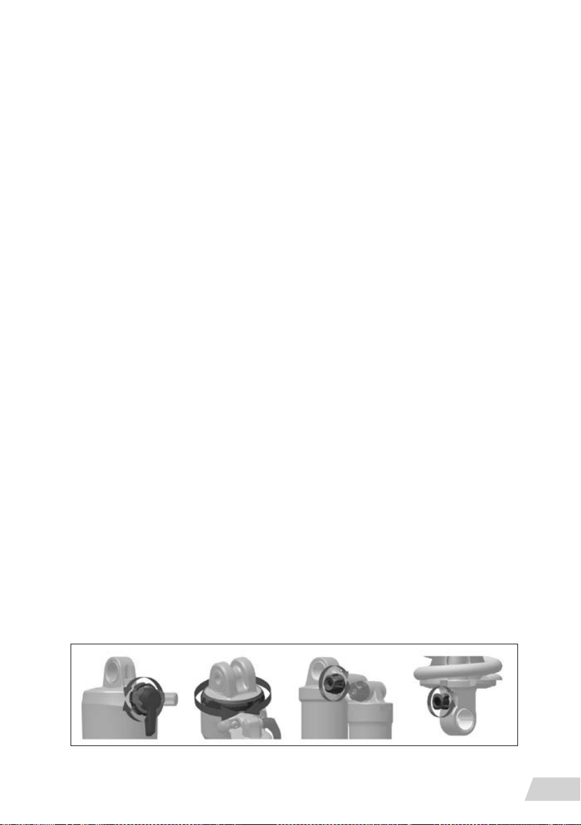
Monarch Rebound damping controls suspension rebound speed after compression. Suspension rebound speed affects wheel contact with the ground, which affects control and efciency. The shock should rebound quickly enough to maintain wheel traction without feeling
‘bouncy’. Too much rebound damping will not allow the shock to rebound quickly enough
for the next bump. To increase the rebound speed, rotate counterclockwise. To decrease the
rebound speed, rotate clockwise.
GENERAL NOTES ABOUT RIDING
11
Page 14
Adjusting compression
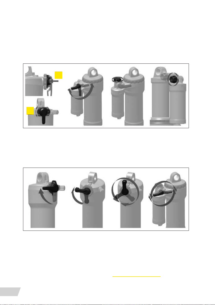
Compression damping controls shock the compression speed during slow compression
stroke scenarios, such as rider weight transfer, small impacts, and cornering, which improves
control and efciency. Too much compression damping makes the suspension feel too rm
over bumps. To increase or decrease compression damping, rotate the knob or lever in the
direction or position indicated on the shock.
1
2
Adjusting threshold
The Threshold, or ‘Pedal’, setting prevents the shock from compressing until moderate impact
or downward force occurs. Use the Threshold setting to increase pedalling efciency on flat,
rolling, and smoother terrain. To activate the Threshold setting, rotate the lever, or actuate the
remote until it reaches the threshold position indicated on the shock.
Adjusting lockout
The Lockout setting prevents the shock from compressing until signicant impact or downward
force occurs. The shock will compress when the force exceeds the damper blow-off circuit resistance. Use the Lockout setting for maximum pedalling efciency on smooth or rolling terrain.
Rotate the lever, or actuate the remote, to lock and unlock the compression damper.
You can nd moreinfo about rear suspensions on www.sram.com/rockshox.
GENERAL NOTES ABOUT RIDING
12
Page 15

Front suspension
Rebound damping controls the suspension fork extension/return speed, which affects traction and
control. Optimal rebound damping allows the fork to extend at a controlled speed and maintain
traction and control. Rebound that is too fast allows the fork to extend too quickly, which causes
the wheel to bounce off objects and the ground resulting in a ‘pogo’ effect. Rebound that is too slow
prevents the fork from extending quickly enough to regain contact with the ground or prepare for
the next impact. Rebound damping can be tuned to rider weight, spring rate and travel, as well as
for terrain and rider preference. As the air pressure or spring rate increases, the extension/return
speed increases. To achieve the optimal setting, rebound damping may need to be increased when
air pressure or spring rate increases. For recommended rebound settings, go www.sram.com/rock-
shox. After setting the sag, adjust the rebound damper, go for a ride, and adjust again as preferred.
Shock pressure chart
FRONT FORK – AIR SPRING PRESSURE
ROCK SHOX YARI RC 27.5” BOOST DEBONAIR, 150MM TRAVEL, 15MM AXLE
<55 KG 55–63 KG 63–72 KG 72-81 KG 81-90 KG 90-99 KG >99 KG
<55 PSI 55-65 PSI 65-75 PSI 75-85 PSI 85-95 PSI 95-105 PSI 105+ PSI 163
ROCK SHOX LYRIK RC 27.5” BOOST DEBONAIR, 150MM TRAVEL, 15MM AXLE
<55 KG 55–63 KG 63–72 KG 72-81 KG 81-90 KG 90-99 KG >99 KG
<55 PSI 55-65 PSI 65-75 PSI 75-85 PSI 85-95 PSI 95-105 PSI 105+ PSI 163
ROCK SHOX PIKE RC 27.5” BOOST DEBONAIR, 150MM TRAVEL, 15MM AXLE
<55 KG 55–63 KG 63–72 KG 72-81 KG 81-90 KG 90-99 KG >99 KG
<55 PSI 55-65 PSI 65-75 PSI 75-85 PSI 85-95 PSI 95-105 PSI 105+ PSI 163
MAX PSI
MAX PSI
MAX PSI
Recommended tire pressure
Tire pressure is an important factor for having the bike ride properly. If the tire pressure is too
high, the tire will not conform to the ground, reducing traction. If the tire pressure is too low,
the tire could pinch flat. It is important to have an accurate pressure gauge when setting tire
pressure; preferably a digital gauge with a 0.03 [bar] (0.5 [psi]) accuracy. The recommended
tire pressure will vary slightly based on rider weight, riding style, and terrain. Some riders may
GENERAL NOTES ABOUT RIDING
13
Page 16
nd it helpful to start a ride at a slightly higher pressure than recommended and let out a little
air throughout the course of the ride until you nd your ideal riding tire pressure. The maximum inflation pressure is 2.6bar (38psi)
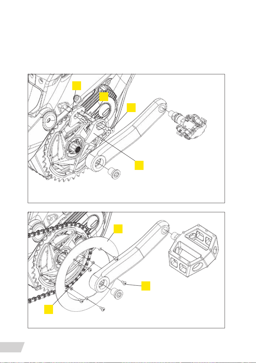
Assembling parts supplied unassembled
1
3
4
2
Chainguide – use only with positive foot-retention devices on the pedals
6
GENERAL NOTES ABOUT RIDING
14
5
7
Chainguard
Page 17
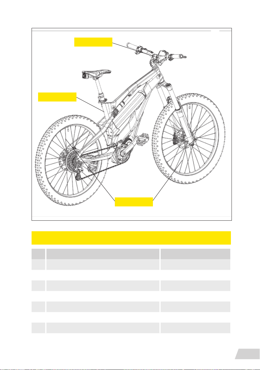
Rear reflector
Front reflector
Side reflectors
CHAINGUIDE OR CHAINGUARD MOUNT
NAME/DESCRIPTION TORQUE [NM]
1 CHAINGUIDE ALU PART -
2 CHAINGUIDE PLASTIC PART -
3 DIN 7991 M5X18 4
4 DIN 7991 M5X12 4
5 CHAINGUARD -
6 CHAINGUARD BUSH -
7 ISO 7045 M4X8 4
GENERAL NOTES ABOUT RIDING
15
Page 18

Battery and charger
Your vehicle is powered by a lithium-Ion (Li-Ion) battery. Always adhere to the following instructions when handling or charging the battery or when using the G6. Only use the Greyp
battery with the corresponding Greyp vehicle. Do not use the Greyp battery with other products or any other battery with the Greyp vehicle, even if it ts.
Turn off the bike, unplug the charger from the battery and remove the battery from the Greyp
vehicle before performing work of any kind, such as installation, maintenance, cleaning and/or
repair. When transporting or handling the battery separately from the Greyp vehicle, ensure the
battery is turned OFF. Touching the contacts when the battery is ON can result in electric shock
and/or injury.
Before riding the vehicle, make sure the battery is properly secured in the frame.
Do not modify, open or disassemble the battery or charger. Modication or disassembly may
result in a short circuit, re or malfunction.
Be careful when handling it and do not drop it.
Battery technical data
GREYP G6 BATTERY PACK INFORMATION
MANUFACTURER: GREYP BIKES D.O.O.
MODEL/TYPE REFERENCE: 6G-01
WEIGHT: 3.5 KG
BATTERY TYPE DESIGNATION: 10INR19/66-6
CELL CONFIGURATION: 10S6P
CAPACITY (AH): 19.3 AH
ENERGY (WH): 700 WH
COMMUNICATION: CAN
APPLICATION USING
ENVIRONMENT:
COOLING: NATURAL CONVECTION
INDOOR AND OUTDOOR, -20~50 °C
BATTERY AND CHARGER
16
Page 19

GREYP G6 BATTERY PACK INFORMATION
PROTECTION TYPE: FUSE/ CELL CHRG TEMP, DISCHRG TEMP /
CELL VOLTAGE
PROTECTION:
OTHER INFORMATION:
CHARGING METHOD: CC/CV
I CHARGE MAX: 9.0 A
I CHARGE NOM: 4.0 A (OPTIONAL: 8.0 A)
I DISCHARGE: 20.0 A CONTINUOUS
U CHARGE MAX: 42.0 V
U CHARGE NOM: 36.3 V
U DISCHARGE END: 25.0 V
U CHARGE END: 41.9 V
CERTIFICATION: UN 38.3 (6TH ED.)
PROTECTION RATING : 40 A/ 0°C TO 55 °C , -20 °C TO 60 °C / 2.5
TO 4.19 VOLTS
SHORT CIRCUIT PROTECTION: 150 A
CELL INFORMATION : LG INR18650-MJ1, LI-ION, 3.63V, 3500MAH
OUTPUT CONNECTOR: ROPD TYPE, AUTOMOTIVE, 48V, 30A, UV
RESISTANT
Important battery information
The connector used for the battery and charger is magnetised (RoPD) and can attract metal
objects. Do not allow any screws or other small, sharp and/or metallic objects to come in
contact with the battery connector, bike charging socket or charger connector.
Keep the battery away from metal objects as that can cause a short- circuit.
Do not allow the battery to overheat. Protect the battery from excessive sun exposure.
Do not expose the battery to an open re or radiator heat.
Do not place the battery in water. Do not directly spray the battery (or the connectors if the
battery is removed) with pressure water.
Do not use a battery that shows any signs of damage (hollow casing, cracked lid, cracked
connector, damaged connector) or is leaking any fluids. Battery liquid can cause skin irritation
and burns. In the event of damage that results in skin or eye contact with any liquid from the
battery, immediately flush with water and seek medical assistance.
BATTERY AND CHARGER
17
Page 20
WARNING! Failure to follow the instructions in this section may result in damage to electrical
components on your vehicle and will void your warranty, but, most importantly, may result in
serious personal injury or death. If your battery or charger exhibits any signs of damage, do
not use it and immediately bring it to your authorized Greyp Bikes retailer for inspection.
WARNING! It is important that you follow the instructions on the label of the battery charger
The battery can be charged whether installed in the vehicle or not. Refer to the appropriate
instructions regarding removing and installing the battery. Only charge the battery at an ambient temperature between 10°C and 30°C (50°F and 86°F). If the outside temperatures are
too hot or too cold, charge the battery inside. For safety reasons, if the battery is too hot or
too cold, it will not charge.
Charging process
Plug the charger plug into appropriate AC outlet (depending on the charger) using the appro-
on bike
priate for the country’s standards.
(QQE input voltage: AC, 50-60 Hz, 90-264 V – FAST CHARGER ON REQUEST)
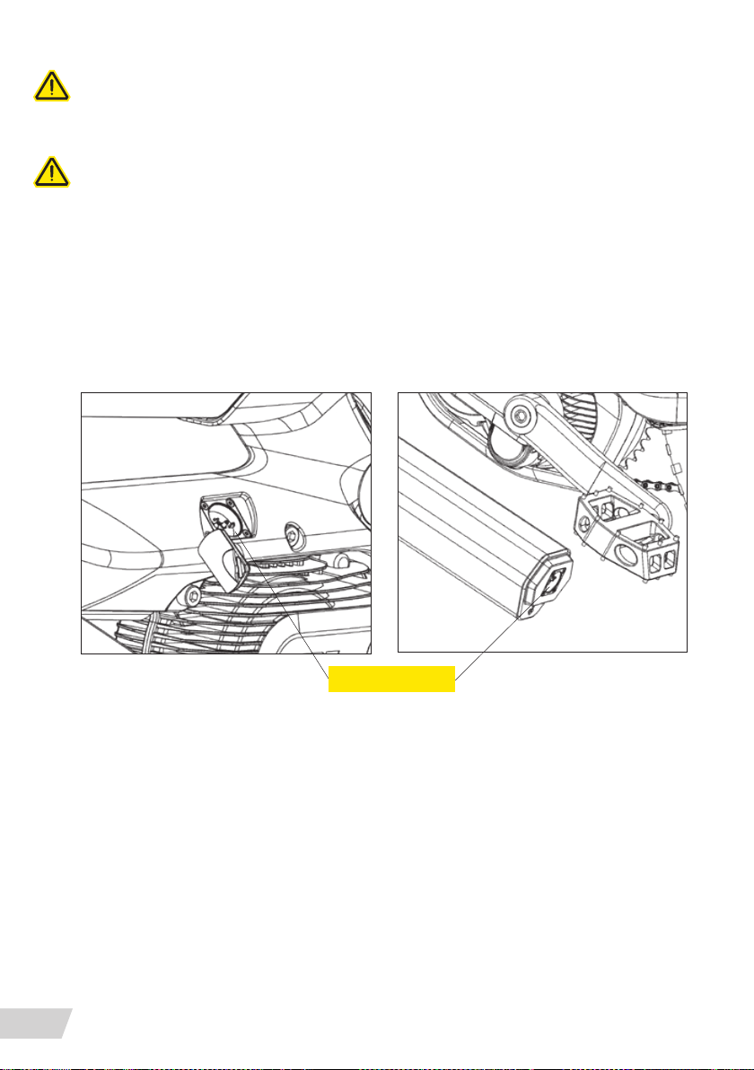
Uncover the charging socket on the bike, then connect the charger to the charging socket on the
bike. It is possible to charge the battery when removed from the bike. In that case, plug the charger
into the battery socket.
During the charging process, the diode on the charger will glow red. When the battery is fully
charged, the diode on the charger will turn green. When monitoring the charging process,
please check the LED light on the charger.
When charging is complete, disconnect the charging plug from the battery socket. Unplug the
charger from the wall socket.
BATTERY AND CHARGER
18
Charging sockets
on battery
Page 21
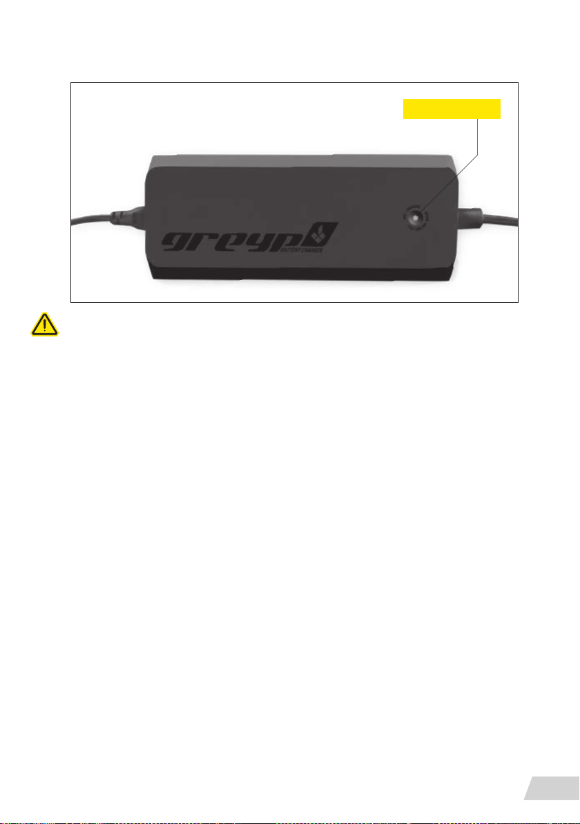
LED indicator
CAUTION: If the red LED flashes during the charging process, a charging error has occurred.
In that case, immediately remove the charger from the socket, discontinue the use of the
motor support and contact an Authorized Greyp Retailer.
The bike should be stored in dry conditions, with a state of a charge (SoC) level between 30
and 40 % if you plan on storing it for a period longer than 1 month. If you plan on storing the
Greyp for longer than 6 months, make sure you leave the bike with a state of a charge (SoC)
between 30 and 40% It is necessary to check the battery frequently, even if the bike is not
being used, in order to avoid permanent damage to the battery.
Strongly reduced operating time after charging can be a sign that the battery is reaching the
end if its useful life and must be replaced. Provided the vehicle has been used properly, approximately 70% of the battery’s original capacity should remain after 2000 charging cycles
or two years.
First start-up and charging
Recharging the Greyp G6 battery takes 5 hours. It is recommended that you don’t wait for the
battery to completely empty before recharging. Try to keep the battery between 20-80 % to
extend the battery life.
The worst thing is to leave a complete empty battery uncharged for a longer period. This could
lead to reduced battery life or permanent damage to the battery pack.
BATTERY AND CHARGER
19
Page 22
System functions
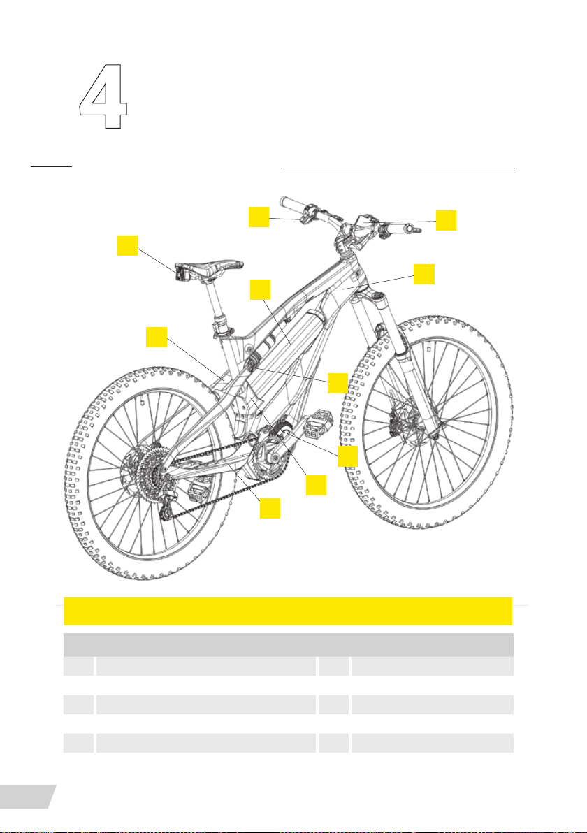
Bike parts
BIKE PARTS
2
3
4
5
8
10
7
6
1
9
NAME/DESCRIPTION
1 DISPLAY UNIT (CIM) 6 CHAINSTAY
2 CONTROL UNIT (CBC) 7 PUSHPLATE
3 REAR CAMERA (BUTS) 8 RATIO LEVER
4 BATTERY 9 FRAME
5 SEATSTAY 10 MOTOR
SYSTEM FUNCTIONS
20
Page 23
Control unit functions
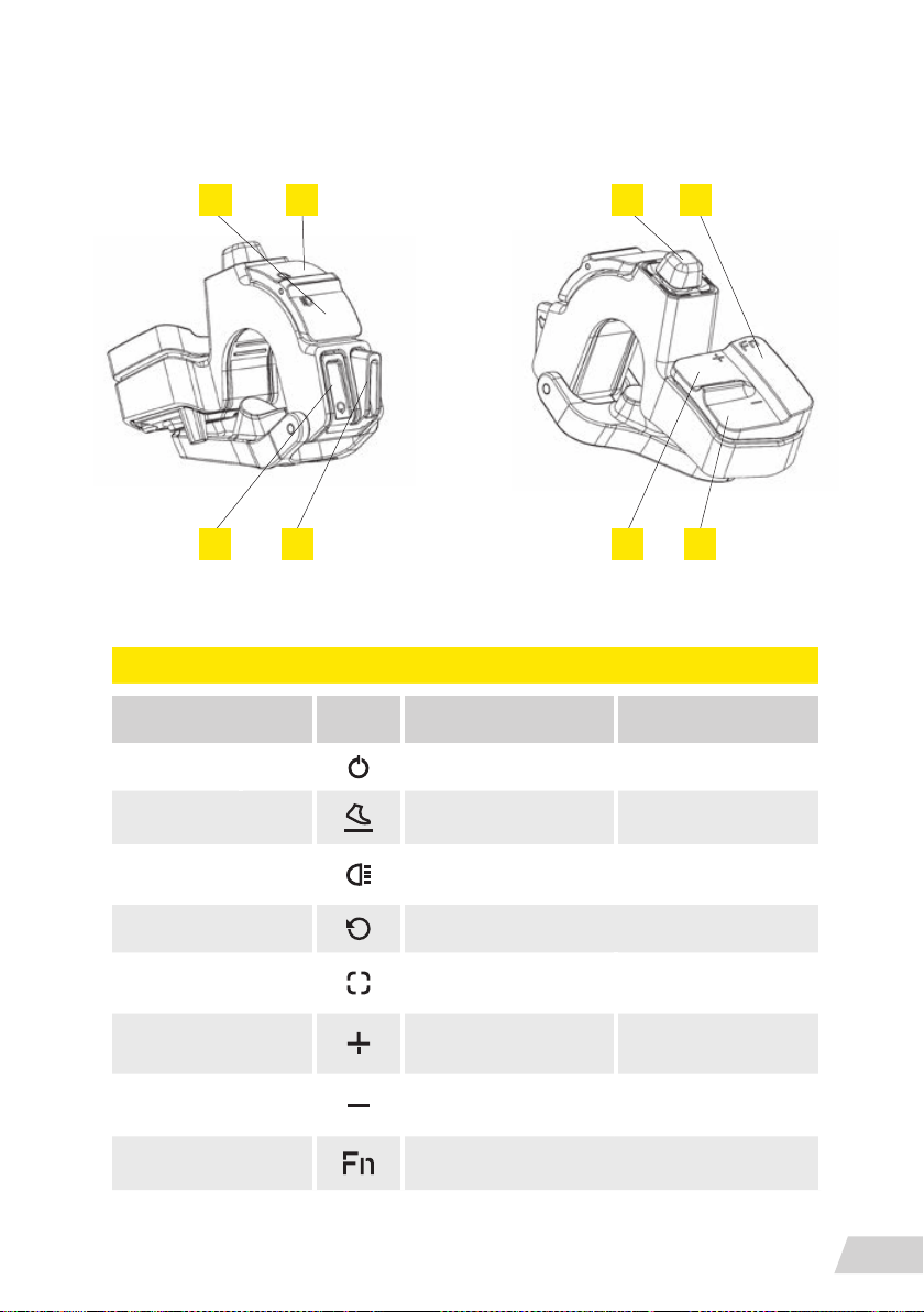
3 4
1 2
LEGEND
NAME/DESCRIPTION ICON FUNCTION TYPE
1 POWER ON/OFF AND STAND BY LONG/SHORT PRESS
2 WALK ASSIST WALK ASSIST PRESS & HOLD
85
76
3 LIGHT
RETRO VIDEO WORKS ONLY WITH MOBILE APP
4
5 JOYSTICK
6 ASSIST LEVEL UP
7 ASSIST LEVEL DOWN
8 FUNCTION WORKS ONLY WITH MOBILE APP
TURN ON/OFF FRONT AND
REAR SIGNAL LIGHTS
SWITCH BETWEEN DISPLAY
FUNCTIONS
INCREASE LEVEL OF
ASSISTANCE
DECREASE LEVEL OF
ASSISTANCE
SHORT PRESS
SHORT PRESS IN ALL
DIRECTIONS
SHORT PRESS
SHORT PRESS
SYSTEM FUNCTIONS
21
Page 24
Display unit information
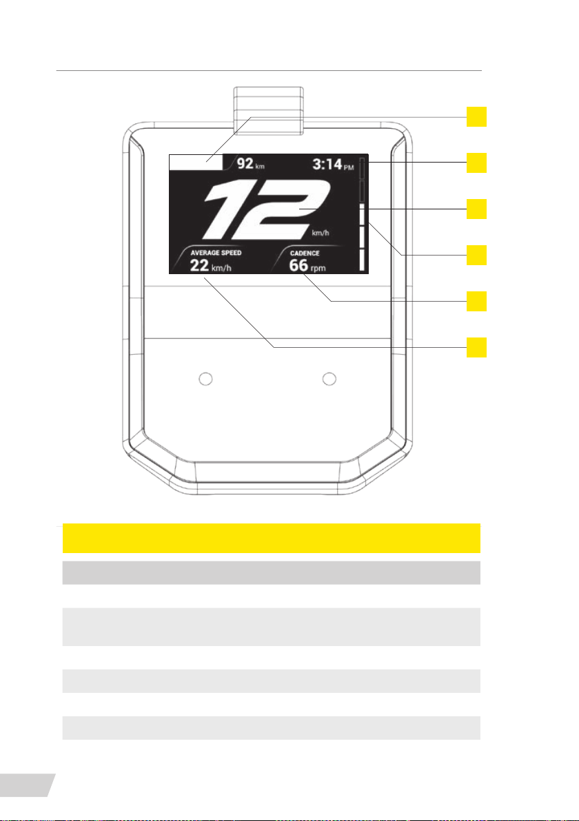
2
4
1
5
6
3
CIM DISPLAY INTERFACE
1 SPEED
2
3 RIDE STATISTICS
4 TIME
5 ASSIST LEVEL
6 CADENCE
SYSTEM FUNCTIONS
22
NAME/DESCRIPTION
BATTERY CHARGE /
REMAINING DISTANCE
Page 25
Power on
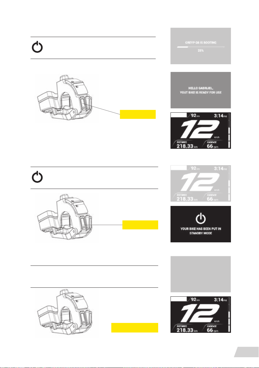
To turn on the bike, short
press the power button
Stand by mode on
To turn on the bike, short
press the power button
Short press
Short press
Stand by mode off
To wake up the bike from stand by mode, press any
button on the control unit or move the bike
Press any button
SYSTEM FUNCTIONS
23
Page 26
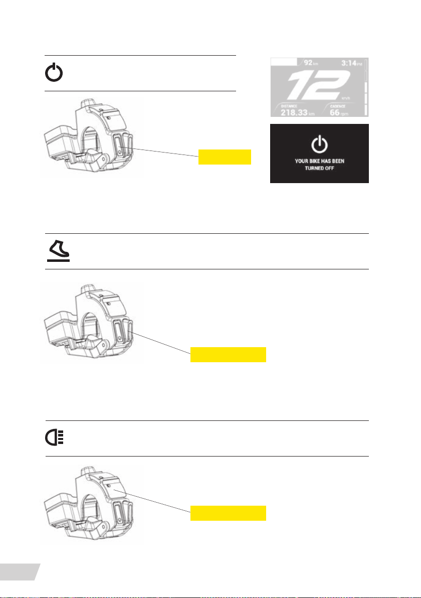
Power off
To turn off the bike, long
press the power button
Walk assist mode
To activate walk assistance mode, press
and hold walk assist button
Long press
Lights on/off
SYSTEM FUNCTIONS
24
Press and hold
To turn the lights on or off, short press
the light button
Short press
Page 27
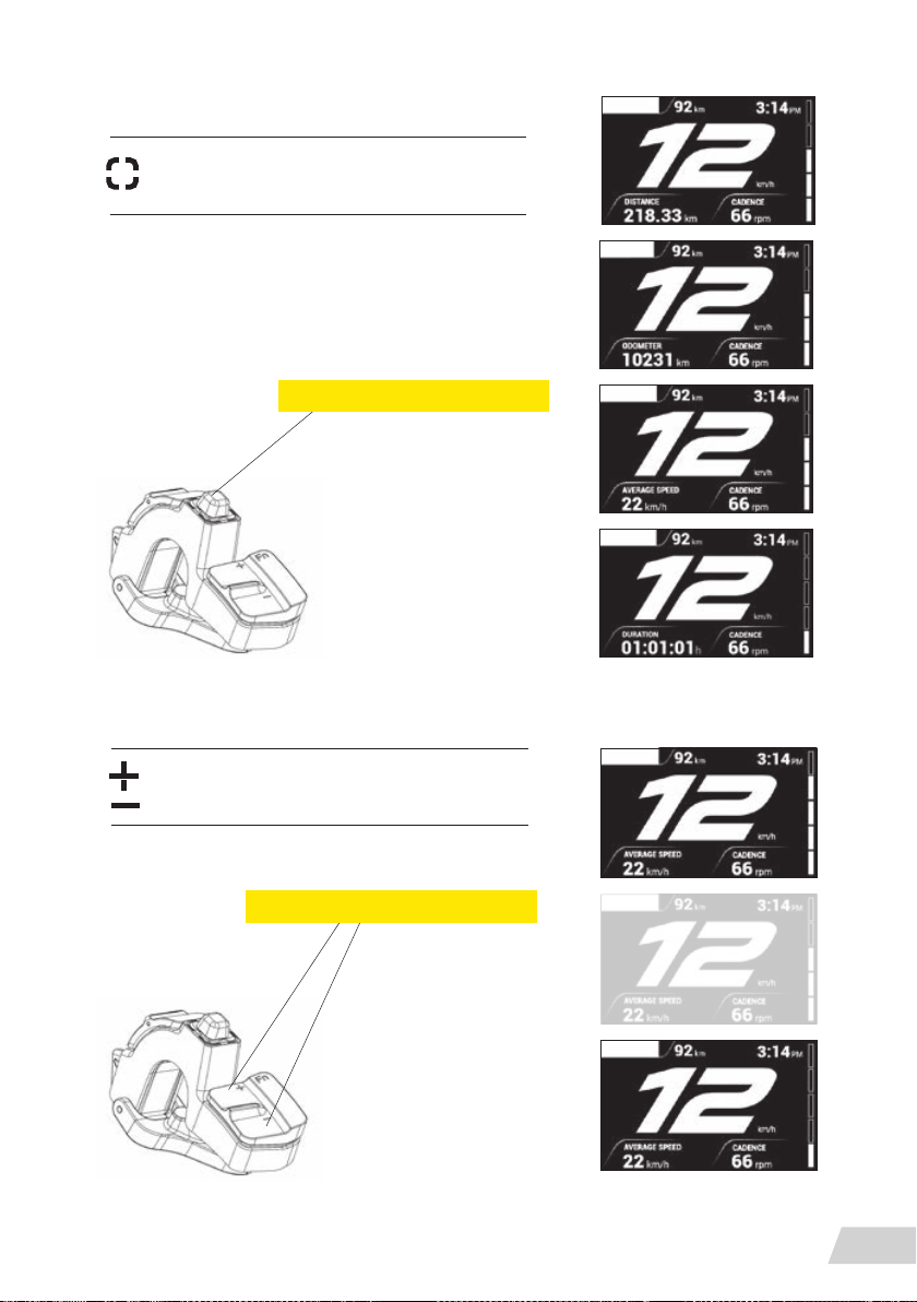
Joystick
To switch between different information on the
display unit, move the joystick up or down
» TRIP
» ODOMETAR
» AVERAGE SPEED
» TRIP TIME
Move in the up or down direction
Assist level up/down
To change the assistance level, short press
the plus or minus assist level button
Short press to change by one level
SYSTEM FUNCTIONS
25
Page 28
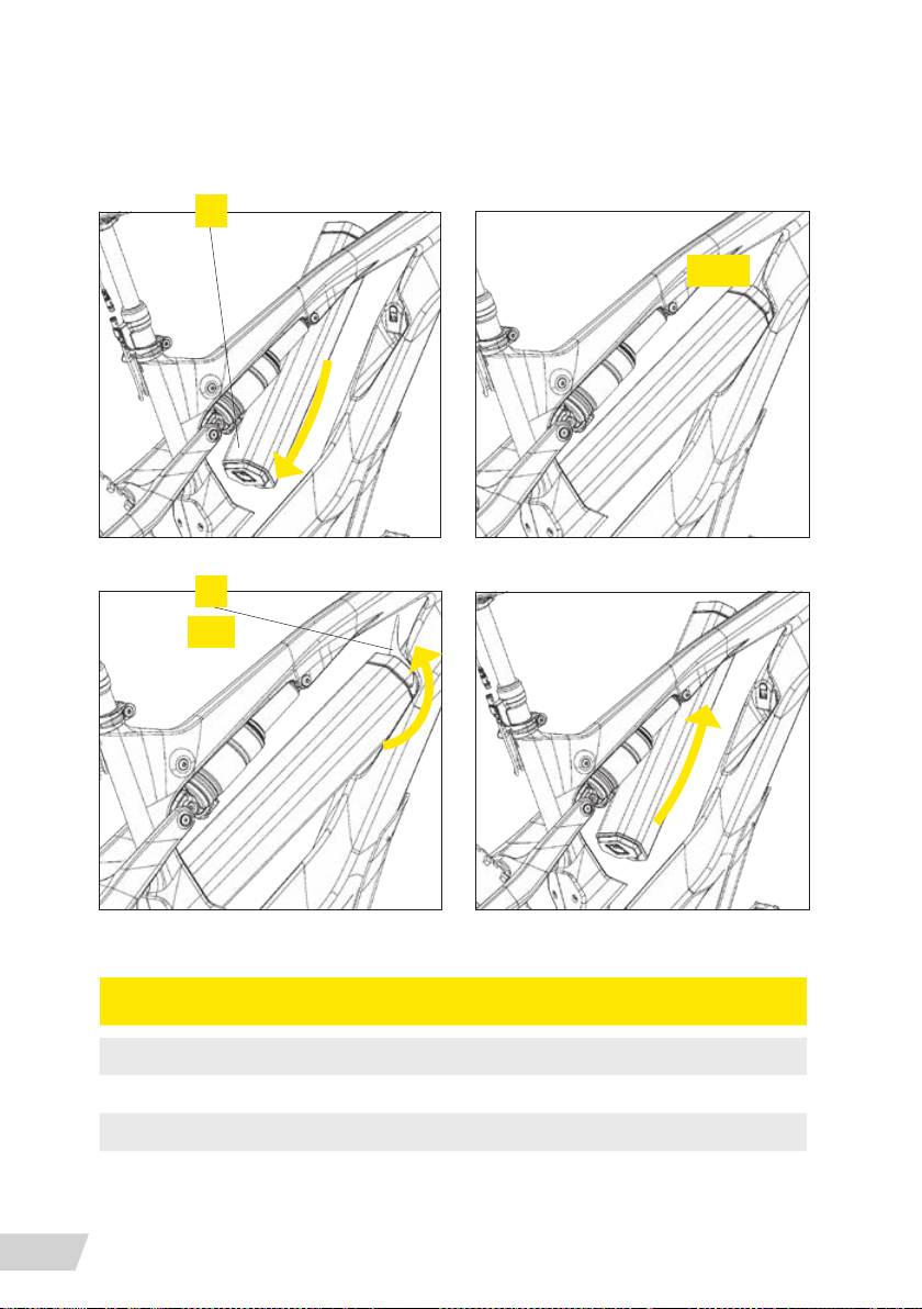
1
2
pull
click
BATTERY PACK MOUNT/DISMOUNT
1 BATTERY
2 BATTERY LOCK
SYSTEM FUNCTIONS
26
NAME/DESCRIPTION
Page 29
Bike usage
Maintenance
The G6.1 and G6.2 are high-performance bicycles.
The G6.3 is an off-road vehicle.
All regular maintenance, troubleshooting, repair and parts replacement must be performed
by an Authorized Greyp Retailer.
Great care should be taken to not damage carbon bre or composite material. Any damage
may result in a loss of structural integrity, which may result in a catastrophic failure. This
damage may or may not be visible on inspection. Before each ride, and after any crash, you
should carefully inspect your vehicle for any fraying, gouging, scratches through the paint,
chipping, bending, or any other signs of damage. If discovered, not ride any further and take
your vehicle to an Authorized Greyp Retailer for a complete inspection.
The lifespan and the type and frequency of maintenance depend on many factors, such
as frequency and type of use, rider weight, riding conditions and/or impacts. Additionally,
the G6 uses a power-assisted drive system, which means more distance at different rates,
depending on the component. Drivetrain and brake components are especially subject to
wear. Periodically have your Authorized Greyp Retailer inspect your vehicle and components.
Exposure to harsh elements, especially salty air (such as riding near the ocean or in the winter)
can result in galvanic corrosion of components, which can accelerate wear and shorten the
lifespan. Dirt can also accelerate the wear of surfaces and bearings. The surfaces of the vehicle should be cleaned before each ride. Proper care and regular maintenance can help increase
the longevity of components. If you notice any signs of corrosion or cracking on the frame
or any component, the affected item must be replaced. While riding, listen for any creaks, as
a creak can be a sign of a problem with one or more components. Periodically examine all
surfaces in bright sunlight to check for any small hairline cracks and if you discover any, no
matter how small, or any damage to components, immediately stop riding and have the part
inspected by your as retailer. The vehicle should also be maintained regulally by an authorized
Greyp retailer, which means it should be cleaned and lubricated. Regularly clean and lubricate
the drivetrain according to the drivetrain manufacturer’s instructions.
BIKE USAGE
27
Page 30

Do not use a high-pressure water spray directly on the bearings. Even water from a garden
hose can penetrate bearing seals and crank interfaces, which can result in increased bearing
and crank wear, which can affect the normal function of the bearings. Use a clean, damp
cloth and bicycle cleaning agents for cleaning. Do not expose the vehicle to prolonged direct
sunlight or excessive heat, such as inside a car parked in the sun or near a heat source such
as a radiator.
It is very important that you use only genuine replacement parts for safety-critical components.
The following parts must only be replaced with original components:
FRAME BRAKE PADS
ELECTRIC CONTROLLERS BATTERY
FORK DISPLAY
ELECTRIC WIRING BRAKE HOSES
BRAKES CHARGER
MOTOR UNIT CRANK SET
HANDLEBAR REMOTE SENSORS
Appropriate spares:
TYRES BRAKES ROTORS INNER TUBE
SCHWALBE NOBBY NIC
G6.1
PERFORMANCE LINE, 70-584
SCHWALBE MAGIC MARY
G6.2
EVOLUTION LINE, 70-584
SCHWALBE NOBBY NIC
G6.3
PERFORMANCE LINE, 70-584
Parts replacement – recommended values
CHAIN WITH CHAIN RINGS 10,000 KM OR SOONER IF NEEDED
TIRES EVERY 3 YEARS OR AT WEAR MARK
BIKE USAGE
28
FORMULA CURA
FORMULA CURA 4
FORMULA CURA 4
203MM FRONT
180MM REAR
203MM FRONT
203MM REAR
203MM FRONT
203MM REAR
PRESTA 27.5
PLUS X 2.8/3.0
TUBE
Page 31

INNER TUBES EVERY 3 YEARS OR WHEN NEEDED
FRONT HUB BEARINGS EVERY 20,000 KM
BRAKE PADS EVERY YEAR OR AT WEAR MARK
BRAKE DISCS EVERY YEAR OR AT WEAR MARK
BRAKE OIL AS SPECIFIED BY PRODUCER
FORK AS SPECIFIED BY FORK PRODUCER
SHOCK AS SPECIFIED BY FORK PRODUCER
OIL IN SHOCK AS SPECIFIED BY PRODUCER
Range
The range on one charge strongly depends on several circumstances, such as (but not only):
» Weather conditions such as ambient temperature
and wind;
» Road conditions such as elevation and road surface;
» Bike conditions such as tire pressure and mainte-
nance level;
» Bike usage such as acceleration and shifting;
» Rider and luggage weight;
» Charge and discharge cycles.
Shifting recommendations
For better range, Greyp advises to shifting according to the speed. For low speeds and setting
off, low gearing is best. The higher the speed, the higher the gear that can be chosen. For
smooth support and optimum range, it is best to release pedal pressure while shifting gears.
» High speed, high gear
» Low speed, low gear
» Release power during shifting
BIKE USAGE
29
Page 32
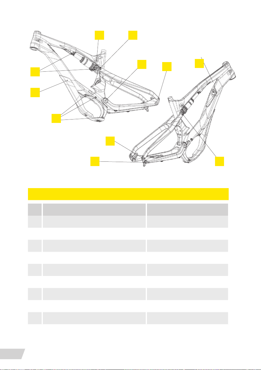
1 4
9
6
8
3
7
Recommended tightening of fasteners
FRAME TORQUE SPECIFICATION
NAME / DESCRIPTION TORQUE [NM]
1 RATIO LEVER / FRAME 8
2 FRAME / CHAINSTAY 20
2
3
5
4
30
3 CHAINSTAY / SEATSTAY 8
4 SEATSTAY / RATIO LEVER 10
5 BATTERY LOCK 3
6 SKID PLATE 5
7 DROPOUT 6
8 FRAME / MOTOR 8
9 RATIO LEVER / REAR SHOCK / FRAME 8
BIKE USAGE
Page 33
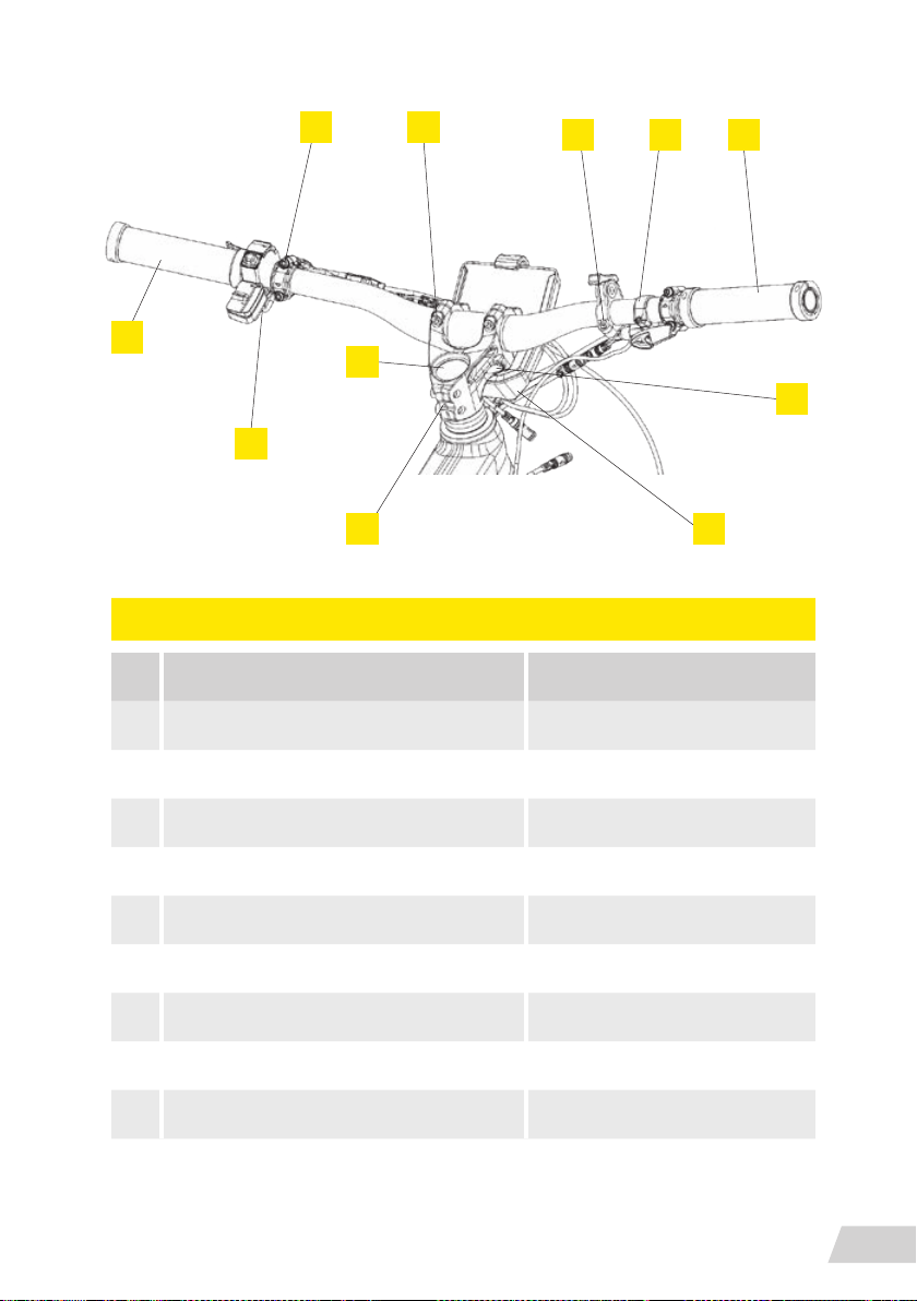
3 5
9
2 1
1
8
5
4
6
HANDLEBAR PARTS / STEM / TORQUE SPECIFICATION
NAME / DESCRIPTION TORQUE [NM]
1 GRIPS / HANDLEBAR 3
2 SHIFTER / HANDLEBAR 4
3 BRAKE LEVERS / HANDLEBAR 4
4 CBC / HANDLEBAR 1,5
5 STEM / HANDLEBAR 9
6 STEM / FRONT FORK 15
7 CIM / STEM < 2 MAX
8 HEADSET / FRONTFORK 6
9 SEATPOST / HANDLEBAR 3
7
BIKE USAGE
31
Page 34
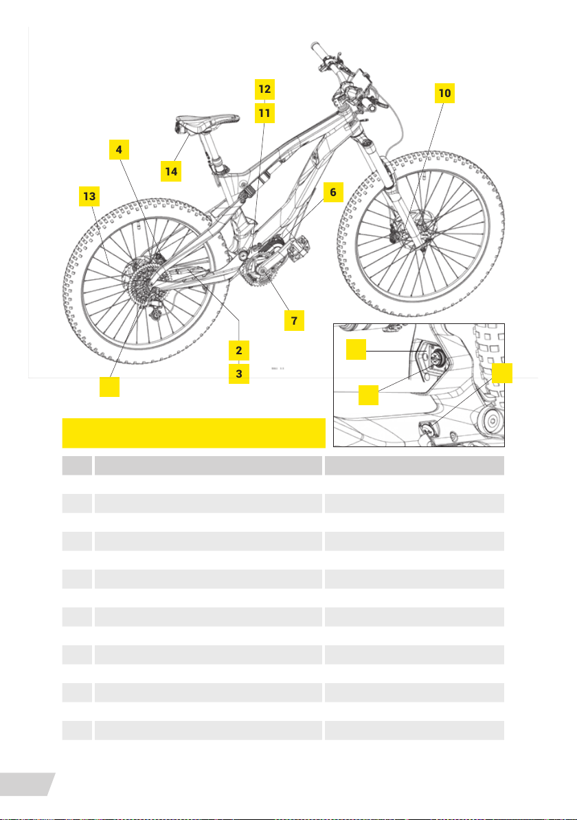
13
12
10
11
4
14
6
7
2
1
3
5
BIKE COMPONENTS TORQUE SPECIFICATION
NAME / DESCRIPTION TORQUE [NM]
1 PUSHPLATE / FRAME 4
2 SPEEDSENSOR / CHAINSTAY 2
3 SPEEDSENSOR / SPEEDSENSOR HOLDER 2
4 REAR BRAKE / CHAINSTAY 6
5 DERAILLEUR / DROPOUT 12
6 CHAINWHEEL / MOTOR 30
7 CRANKARMS / MOTOR 40
8 Y WIRING / PUSHPLATE 1
9 Y WIRING / FRAME 1
10 FRONT BRAKE / FRONT FORK 6
11 CHAINGUIDE ALU PART / FRAME 4
12 CHAINGUIDE PLASTIC PART / ALU PART 4
13 SPEEDSENSOR MAGNET / WHEEL SPOKES < 2 MAX
14 SEAT POST / SEAT 10
9
8
32
BIKE USAGE
Page 35
Cleaning the bike
Most cleaning can be done with soap, water, sponges and brushes.
» Avoid using high-pressure sprayers because water
can penetrate through seals.
» Avoid using corrosive soaps and strong solvents –
always use cleaning products intended for an electric bicycle
» For an extremely dirty chain we recommend use
of a solvent-bath chain cleaner.
Chain
After every wash, the chain should be wiped and lubricated. After every few rides, lube slightly.
After every 400 km, check for chain elongation. Use a chain-elongation gauge to determine
whether the chain should be replaced.
Fork
Wipe and clean the forks after every ride. Full fork service every 125 hours or once a year
(whichever comes rst). For specic detail check suspension manufacturer service manuals.
Shock
Wipe and clean the forks after every ride. Full fork service every 125 hours or once a year (whichever comes rst). For specic details, check the suspension manufacturer service manuals.
Have all repairs performed only by an authorised bike dealer.
Lubrication
Consult with your retailer to choose among the many types of chain lubes best suited to your
climate and riding conditions. Every month, lubricate all of the pivot points of the rear derailleur, as well as on the jockey wheels.
CLEANING THE BIKE
33
Page 36

Warranty
General
Greyp products have been manufactured and tested to the highest quality standards by Greyp
Bikes d.o.o. This Limited Warranty offered by Greyp Bikes d.o.o. covers defects in material or
workmanship in new Greyp products. Greyp warrants this product against defects in material
or workmanship for a period of 24 months after the rst purchase. Greyp will replace any
product or part of the product that proves defective due to improper workmanship and/or material, under normal installation, use, service and maintenance. If Greyp is unable to provide a
replacement and if a repair is not practical or cannot be made in a timely fashion, Greyp may
elect to refund the purchase price in exchange for the return of the product.
This warranty extends to the original purchaser only and is non-transferable. This warranty does
not apply to rental or commercial use bicycles. Only consumers purchasing Greyp products from
authorized Greyp retailers or resellers or through the Greyp website may obtain coverage under
our limited warranties. This warranty does not cover any damage or defects resulting from a
failure to follow instructions in the owner’s manual, alterations to the original design, acts of God,
accident, misuse, neglect, abuse, improper assembly, operator error, water damage or improper
follow-up maintenance. Greyp explicitly exempts from coverage any damage to bicycles used for
jumping, stunt riding, rental programs, observed trials and any similar extreme riding or events.
Incidental and consequential damages are also not covered. Greyp does not cover the cost of
international warranty shipping at any time, for any reason. This warranty is expressly limited
to the replacement of defective parts with those of equal or greater value at the sole discretion
of Greyp Bikes d.o.o.
The repair, replacement or refund of the purchase price, as provided by this warranty, is the
exclusive remedy of the purchaser. Greyp bikes neither assumes nor authorizes any person to
create for it any other obligation or liability in connection with this warranty. Greyp bikes shall
not be liable to the purchaser or any other person for any incidental, special or consequential
damages, arising under this warranty or any implied warranty, including without limitation,
damages for personal injury, property damage or economic losses, whether based on the
contract, warranty, negligence or product liability in connection with their products.
Some components of Greyp bikes are subject to wear and tear due to their function. The rate
of wear will depend on care and maintenance and the way the bike is used. Bikes that are
often left in the open may also be subject to increased wear through weathering. The compo-
34
WARRANTY
Page 37

nents below require regular maintenance. Nevertheless, sooner or later they will reach the end
of their service life, depending on the conditions and intensity of use. Parts that have reached
their limit of wear and tear must be replaced.
RECHARGEABLE BATTERY CHAINRINGS
DRIVE CHAIN LAMPS
BRAKE PADS INNER TUBES
BRAKE FLUID (DOT) SPROCKETS
BRAKE DISKS/ROTORS SADDLE COVERING
BRAKE HOSES LUBRICANTS
BRAKE CABLE HOUSING
SEALS OF SUSPENSION ELEMENTS CHAIN GUIDE ASSEMBLY
GRIPS BASHGUARD
CABLES/CONNECTORS PEDALS
HYDRAULIC DROPPER SEALS AND
REPLACEMENTS PARTS
Battery
The Greyp lithium battery is guaranteed to have 70% of its original tested capacity at the end
of the warranty Period. If the battery fails completely during the rst 24 months from the
original date of purchase, it will be replaced or repaired at no charge. Lithium batteries require
care and some maintenance to maximize life expectancy. Charging the battery while the bike
is exposed to the sun (air temperature above 30 °C) will shorten its service life. Abusing the
battery will void your warranty.
The warranty is void in the following cases:
» if damage is caused by power surge
» if damage is caused by the use of an improper charger
» if damage is caused by improper maintenance or other such misuse
» if damage is caused by normal wear
» if damage is caused by water damage
» if the battery is charged below 0°C
» if the battery is not charged every month
If a battery needs to be removed for return shipment to Greyp, it is the customer’s responsibility to safely remove and send the battery to Greyp at their own cost. Greyp will reimburse
WARRANTY
35
Page 38

the customer for its own labour & replacement parts in the rst 24 months of bike ownership.
Greyp will pay to return the battery to the customer. Greyp retains the right to repair or replace battery at its sole discretion. All lithium batteries must be shipped as Class 9 dangerous
goods (HAZMAT) and must be shipped in accordance with all local and international laws.
Lithium batteries sold by Greyp can NEVER be taken on board a passenger aircraft.
Frame
The Greyp frame is covered by a warranty against defects for 24 months from original date
of purchase for the original owner. If a frame is found to be defective, EU shipping, parts and
labour to replace the said frame is paid by Greyp for the rst 24 months from the original
date of manufacture. The cost of repairing/replacing custom paint is never included in frame
warranty at any time.
Motor
The motor is warranted for 24 months from original date of purchase to be free from defects.
In the event of a warranty claim requiring the motor to be returned to Greyp, customer is responsible for removal and shipment to Greyp. Greyp pays for the parts, in-house labour and
return shipping.
Electronics
The electronics component are warranted for 24 months from the the original date of purchase to be free from defects. In the event of a warranty claim requiring the electronics to
be returned to Greyp , the customer is responsible for removal and shipment to Greyp. Greyp
pays for parts, in-house labour and return shipping.
Brakes
The brakes are warranted for 24 months from the original date of purchase to be free from
defects. Normal wear of the brake pads is not covered. Warranty claims on components are
made in accordance with component manufacturer’s guidelines. In the event of a warranty
claim requiring the components are to be returned to Greyp, the customer is responsible for
removal and shipment to Greyp. Greyp pays for parts, in-house labour and return shipping.
Suspension
The suspension units are warranted for 24 months from the original date of purchase to be
free from defects. Normal wear of the suspension, such as oil changes and leaking seals are
not covered. Warranty claims for components are made in accordance with the component
manufacturer’s guidelines. In the event of a warranty claim requiring the components to be
returned to Greyp, the customer is responsible for removal and shipment to Greyp. Greyp pays
for parts, in-house labour and return shipping.
WARRANTY
36
Page 39

Drivetrain
The drivetrain includes the sprockets, shifting system, chain and wheels. Drivetrain units are
warranted for 24 months from the original date of purchase to be free from defects. Normal
wear and tear of the drivetrain, such as chain and sprocket wear, tire flats, bent wheels and
worn tires are not covered. Warranty claims for components are made in accordance with the
component manufacturer’s guidelines. In the event of a warranty claim requiring the components to be returned to Greyp, the customer is responsible for removal and shipment to Greyp.
Greyp pays for parts, in-house labour and return shipping.
How to le a claim
Greyp Bikes d.o.o. will not provide any warranty coverage unless claims are made in compliance with all the Greyp Bikes d.o.o. Warranty Terms and Conditions and the proper return
procedure is not followed. To request a warranty service, the Greyp Customer Service Department needs to be contacted and the following information needs to be clearly provided:
» The sales receipt or other evidence of the date and place of purchase
» Full name, contact details (including telephone number and email address)
» Build number of the bike
» A description of the problem
» Images or video evidence of the problem
» Delivery of the product or the defective part, postage prepaid and carefully
packed and insured, to Greyp Bikes d.o.o. or an agreed dealer
The product or defective part has to be delivered to Greyp Bikes d.o.o. or an agreed dealer postage prepaid and carefully packed and insured. When the warranty service is completed,
any repaired or replacement product or part will be returned to the customer postage prepaid.
Greyp Bikes d.o.o. reserves the right to inspect any defective components or products to determine whether a repair or replacement is required.
Greyp Bikes d.o.o., Ljubljanska 7, 10431 Sveta Nedelja, Croatia
WARRANTY
37
Page 40

Disposal
The drive unit, on-board computer including operating unit, battery pack, speed sensor, accessories and packaging should be disposed of in an environmentally correct manner.
Only for EC countries:
According to the European Guideline 2012/19/EU, electrical devices/tools that are no longer
usable, and according to the European Guideline 2006/66/EC, defective or used battery packs
/ batteries, must be collected separately and disposed of in an environmentally correct manner.
The integrated battery pack in the on-board computer may only be removed for disposal.
Opening the housing shell can destroy the on-board computer.
Please return battery packs and on-board computers that are no longer usable to an authorised bicycle dealer.
Batteries and chargers must not be disposed of in your household trash! All batteries and
charges must be disposed of in an environmentally friendly manner, in accordance with the
battery disposal regulations in your country or state. Ask your authorized Greyp retailer for
information on how to dispose of a battery or charger and any applicable take-back program.
DISPOSAL
38
Page 41
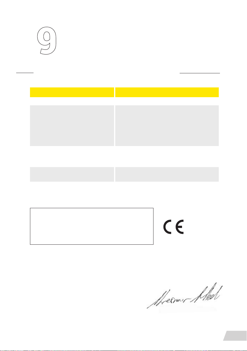
EC – Declaration of conformity
MANUFACTURER GREYP BIKES D.O.O.
ADDRESS LJUBLJANSKA 7, 10431 SVETA NEDELJA, CROATIA
GREYP G6.1 – PEDELEC
(EPAC - ELECTRIC POWER ASSISTED CYCLE)
DESCRIPTION OF PRODUCT
NAME AND ADDRESS OF THE
PERSON AUTHORISED TO COMPILE
THE TECHNICAL FILE
THE PLACE AND DATE OF
THE DECLARATION;
Hereby we expressly declare that the products listed
above full all the relevant provisions of the:
Machinery Directive (2006/42/EC), Electromagnet ic
compatibility (2014/30/EC), Radio Equipment Directive
(2014/53/EU), Low Voltage Directive (LVD) (2014/35/
EU), ROHS 2 Directive (2011/65/EU)
GREYP G6.2 – PEDELEC
(EPAC - ELECTRIC POWER ASSISTED CYCLE)
GREYP G6.3 – OFF-ROAD VEHICLE
ZVONIMIR SUČIĆ, LJUBLJANSKA 7,
10431 SVETA NEDELJA, CROATIA
08/05/2019, SVETA NEDELJA
The following harmonizing standard was
applied to the G6.1 and G6.2:
EN 15194:2017 Bicycles – electrically power
assisted cycles – EPAC bicycles.
The following standard was used
for G6.1, G6.2 and G6.3:
EN ISO 4210
Krešimir Hlede
COO Greyp Bikes d.o.o.
EC – DECLARATION OF CONFORMITY
39
Page 42
Page 43
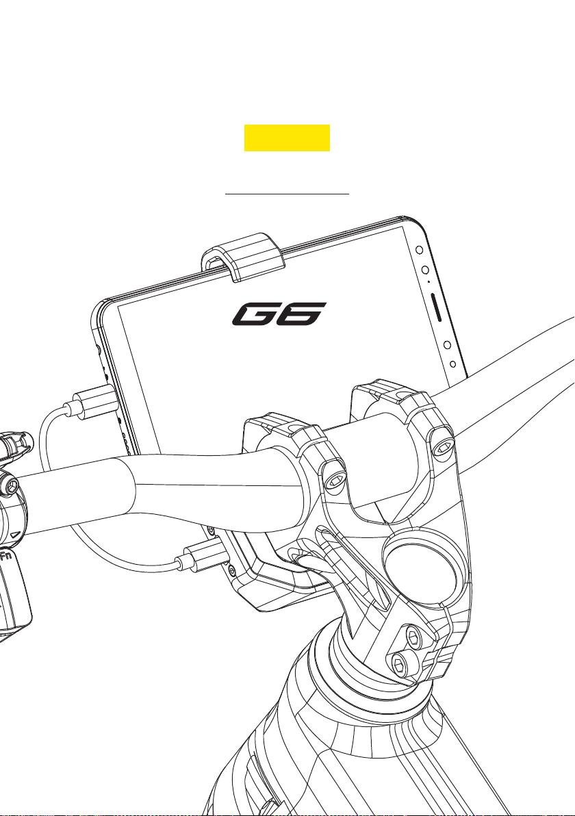
ENGLISH
ENGLISH
MOBILE APPLICATION
Page 44
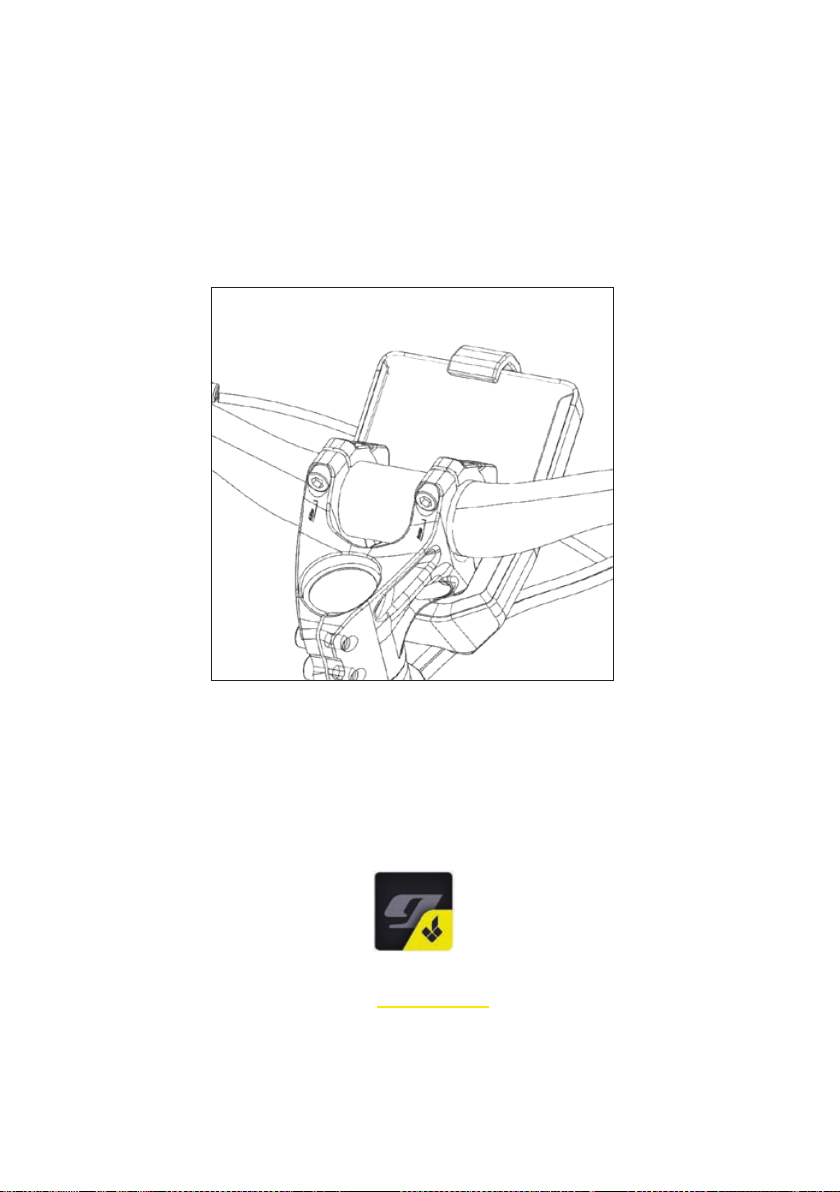
Greyp G6 with a 3G-module and eSIM is permanently
connected to the internet in over 140 countries (you can
nd a list of all the countries on www.greyp.com). Just
plug the mobile phone into the CIM and pair the bike with
the mobile device.
The Greyp G6 mobile application is available
on the Google PlayStore.
Page 45
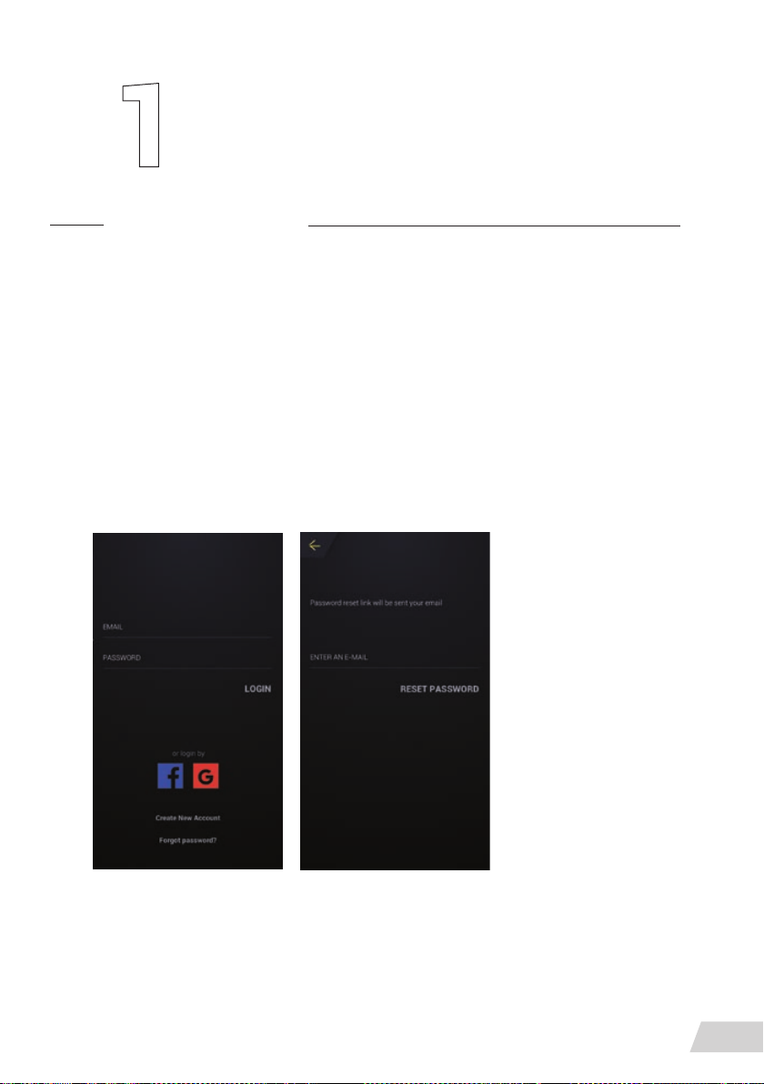
Introduction
The Greyp G6 mobile application has Remote Control and Dashboard working modes and
both of these have corresponding parts that give you much more. So let’s start from the beginning and show you how to connect to your bike.
Onboarding
First, you need to go through the on boarding process and set up your account.
Connect to GVC
You are able to create your account via Facebook, Google and Greyp Vehicle Cloud. If you
already have an account, login with your existing email and password.
Forgotten password
If you have forgotten your password, please select forgot password on the landing screen and
enter your email. An email will then be sent to your email address.
Please follow the steps to be guided through the password reset process.
INTRODUCTION
43
Page 46
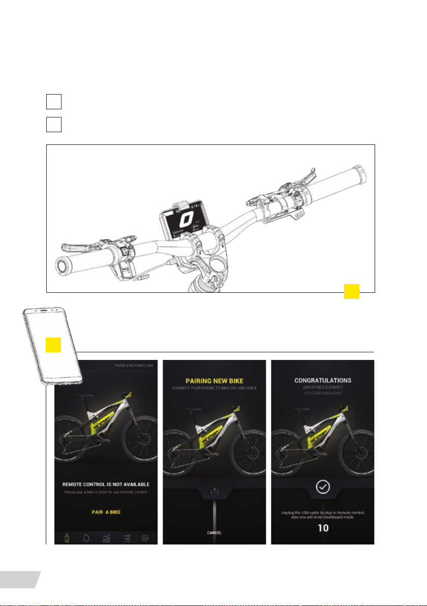
Bike pairing
After you have successfully created
an account, follow these steps:
Turn on your bike and wait for it to show the driving screen
1
Turn on your mobile app and select “Pair a bike”
2
2
1
44
INTRODUCTION
Page 47
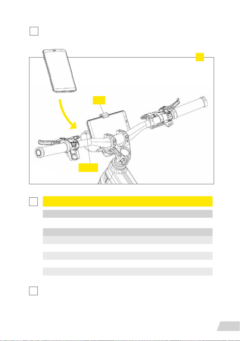
Plug the USB connector into the bike and the corresponding end into the mobile phone
3
and let the two of them do their thing
pull
plugin
3
4
5
POSSIBLE OUTCOMES
SUCCESS
YOU CAN NOW USE YOUR BIKE WITH YOUR MOBILE PHONE
FAIL
SOMETHING WENT WRONG
MAKE SURE NOBODY ELSE IS ALREADY PAIRED TO THE BIKE
MAKE SURE THAT THE BIKE HAS CONNECTIVITY
MAKE SURE THAT THE MOBILE PHONE HAS CONNECTIVITY
MAKE SURE THE USB CABLE IS NOT BROKEN
When pairing is successful, leave mobile phone plugged in to continue to Dashboard
mode or disconnect the USB cable to continue to the Remote control screens
INTRODUCTION
45
Page 48
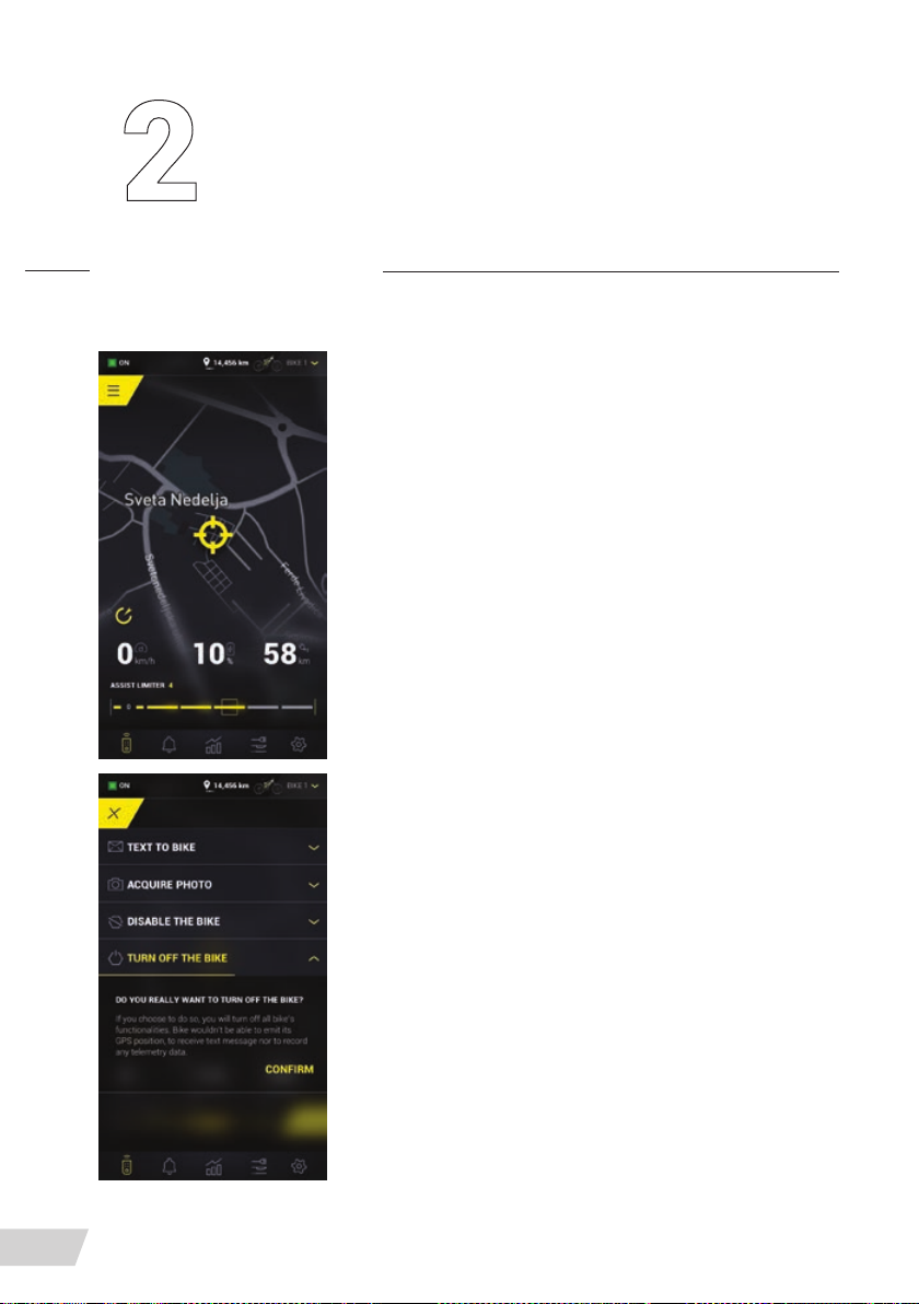
Remote control
This section allows you to control your bike remotely, see its
current status and give you insight into the data generated
by your bike. It is divided into the following sections
» Remote control
» Notications
» Activity
» Feed
» Settings
Navigation through the application is done by switching
through the tab bar at the bottom of the screen.
In the upper part of the application, you have a bike status bar
that is shown in all the mentioned sections and it displays:
» Last known bike status
» User distance to last known bike position
REMOTE CONTROL SECTION
In the central part of the screen, you can see last known bike
position along with last known speed, the current battery
charge and the estimated range based on the current charge.
Just above tab bar is the assist limiter control, which allows
you to set the current maximum assistance level on the bike.
REMOTE CONTROL
46
By pressing the button in the upper left corner, you gain
access to following features:
TEXT TO BIKE
Send a message of a maximum of 100 characters to the
bike. The message will be presented on the CIM (Central Intelligence Module)
Page 49
ACQUIRE PHOTO
Acquire a photo from the bike’s front or rear camera so you can see it’s surroundings
KILL SWITCH
Disable the bike remotely so whoever is using it thinks it is turned off. Anybody using your
bike will be presented with a message that the bike is disabled and to return it to the owner
To enable the bike again, just plug your mobile phone into the USB and wait for the bike and
mobile to do their stuff
TURN OFF BIKE
If your bike is turned on or in standby mode, you can turn it off remotely
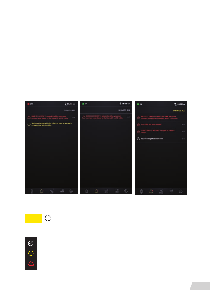
NOTIFICATIONS SECTION
The section of the application that allows you to review all notications provided by the
system. Notications are visible until dismissed.
NOTE
Dismissible notication can be dismissed by pushing the joystick
while using the bike with or without a phone.
Types of messages available on STEM display and in Mob app
INFO MESSAGES: White colour
WARNING MESSAGES: Yellow colour
ALERT MESSAGES: Red colour
REMOTE CONTROL
47
Page 50
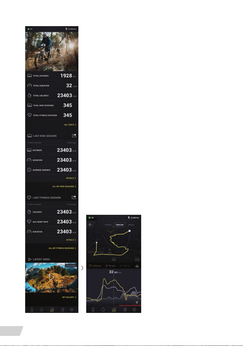
ACTIVITY SECTION
In this section, you have an overview of your current data aggregated by your rides on the bike.
Every time you reset your ride, session data is aggregated in
our cloud and presented to you so you can track your activity.
The rst section shows the following data
» Total distance, Total duration, Total calories, Total number
of ride sessions, Total number of tness sessions
By selecting all stats, you can see the aggregated data and
lter data by
» week, month, year, All time
The ride session show
» Last ride session distance, Last duration of ride sessions,
Average cadence during the last ride session, Number of
videos recorded during the last ride session
The tness session section gives you insight into
» Number of videos recorded during the last tness session,
Calories burnt during the last tness session, Average heart
rate during the last tness session, Total duration of the last
tness session
The video section shows you all the videos recorded via the
camera in dashboard mode. The last video is presented in this
section or you can see all the videos by clicking on My Gallery.
REMOTE CONTROL
48
Ride/Fitness session
You can preview details of the
last session by selecting the
details under each section, or
see data from past sessions by
selecting “All My Ride/Fitness
Sessions”.
When the session is selected,
you will be presented with a
map and a timeline showing
your ride on the map and data
generated during that trip.
Page 51
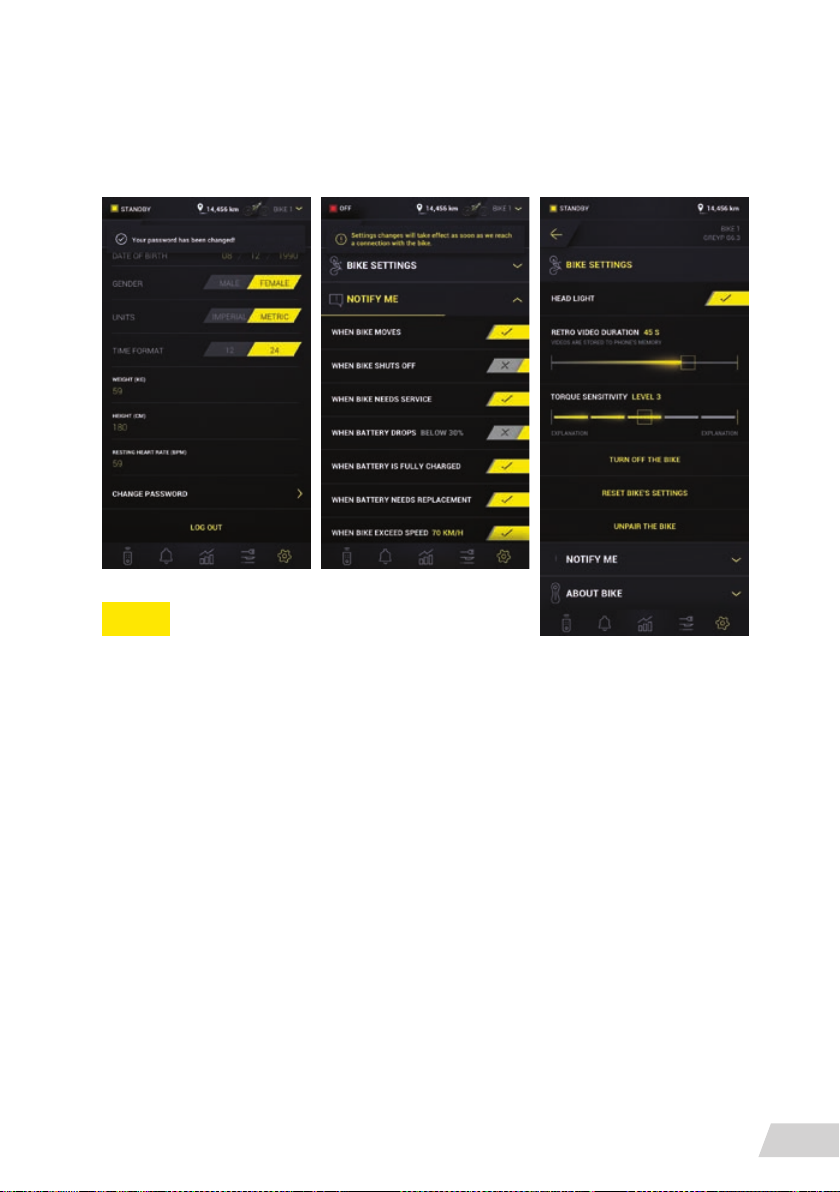
SETTINGS SECTION
Allows you to view personal information and info related to the bike.
View allows you to view and adjust: 1. Personal settings,.2. Bike settings
NOTE
1.PERSONAL SETTINGS
Allows you to update the information you previously entered during account creation. Also,
you can log out of the app.
2.THE BIKE SETTINGS HAVE THREE OPTIONS:
» Bike settings, Notify me, About bike
In the bike section, you can control the bike headlights, retro video duration, set bike torque
sensitivity, turn the bike off, reset the bike settings and unpair the bike.
In the Notify Me section, a toggle buttonallows you to change a setting and get notications
» when the bike moves, when the bike shuts off for any reason, when the bike needs servic-
if you have not previously paired the bike, you can
do this in this application section.
ing, when an error in the system is detected, when the battery SOC drops below N%, when
the battery is fully charged —> Battery was charging on the bike and is now fully charged,
when the battery needs replacement, when bike exceeds N% speed —> During driving, the
bike has exceeded a certain speed
The third section is About Bike. This presents simple information about the bike, motor
and battery.
REMOTE CONTROL
49
Page 52
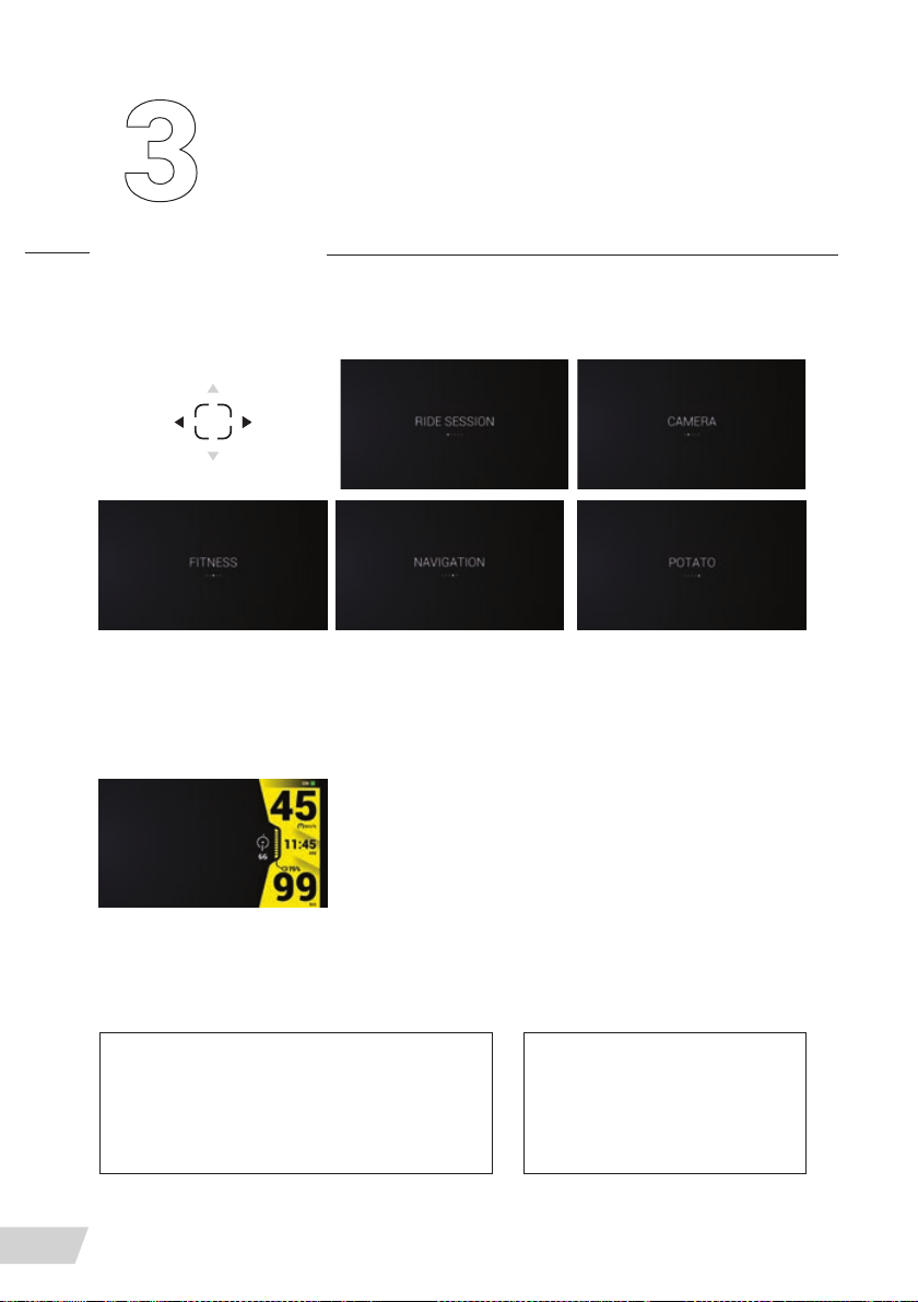
Dashboard
In order to use the application during the bike ride, it is important to have your mobile connected to the CIM (Central Intelligence Module).
The dashboard has ve sections. You navigate through the screens
with the CBC, using the joystick:
Ride session, Fitness session, Camera (a joystick button that can be activated regardless of
which section you are in), Potato and Navigation.
The right side of the screen is the same in all sections and
displays the following measurements:
Bike state, SpeedM TimeM SOC (state of charge) + Battery
barM RangeM Compass/Cadence (Section) – depending on
the application section (one or the other)M Assistance level
Every bike ride is an experience we care about.
Use of the bike is simplied and many things happen automatically. One of them is a ride
session. There are two options:
50
AUTOMATICALLY
The ride session is automatically run every
time a user rides a bike. End of ride and pause
take place under predened criteria.
DASHBOARD
MANUAL
The user can nish the ride
session manually by long
pressing the joystick
Page 53
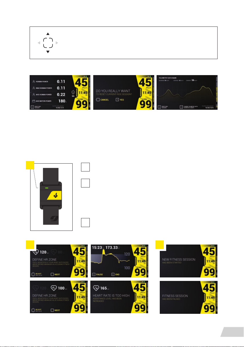
The user can get additional information by using the CBC, pushing the
joystick up/down
Additional information:
FITNESS SESSION
In its standard bike equipment, the Greyp G6 bike has a heart rate monitor. This can be used
during a bike ride.
Using the heart rate monitor is simple and involves the following:
1
Turn the heart rate monitor on; the light must be green
1
Connecting the monitor with the bike is automatically
2
Open the tness section in Dashboard mode
Choose a heart rate zone (it is easy to choose a zone; you
have two yellow spots on the screen - just put your nger on
the spot and drag it up or down depending which zone you
want to adjust
With the CBC joystick, you can switch on / pause / end the
3
tness session
2 3
DASHBOARD
51
Page 54
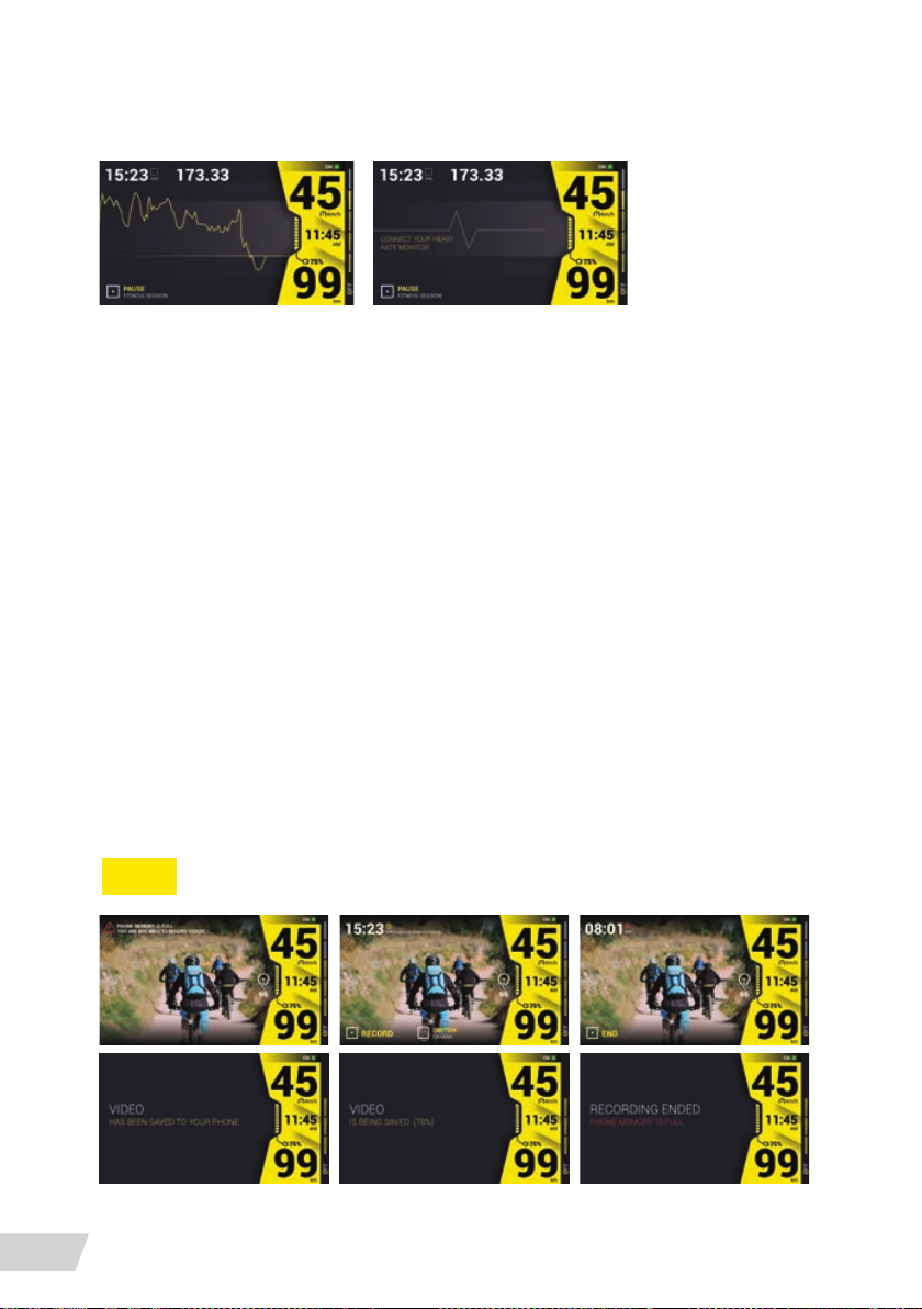
If paring the bike with the heart rate monitor is set correctly, you will see your heart beat on the
display. If the paring is not set correctly, you will get a notication to repeat the paring process.
Heart rate options:
If the heart rate is being sent by the bike sensor, the bike will automatically adjust the assistance level. In this case, you will get a notication on the display.
If you pause the tness session, we’ll keep the current session’s data. On ending the current
tness session, you will see all the details, graphic timelines and data related to it.
Each tness session is saved in the application under Activity in remote control mode.
CAMERA
Usage of the cameras is only available in camera mode. One camera, a 1080@30fps wide-angle one, is positioned on the cockpit beneath the dashboard and the second rearward facing
camera is beneath the saddle.
The camera options are:
» You can use and switch cameras during the ride.
» Start or end the usage of the cameras using the CBC joystick.
» You will be notied about the memory status on your mobile phone.
All data from the cameras is automatically saved on your mobile device.
52
NOTE
DASHBOARD
Do not use rear camera view as rear mirror because picture is flipped.
Page 55
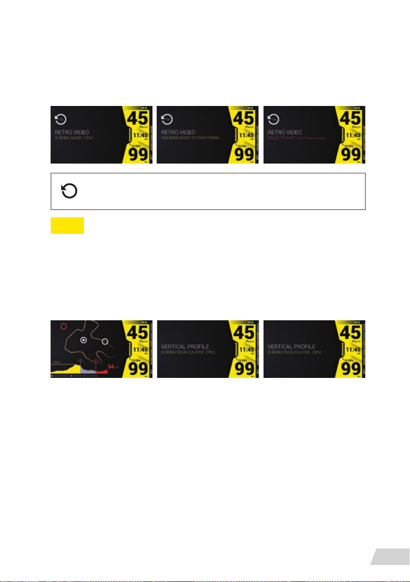
RETRO VIDEO
This system allows you to do a video stream on both cameras lasting 12 minutes. The recording is in a loop.
The bike user can access the videos at any time.
There is a button on the CBC, joystick, that launches the action retro video. It
can also be started from any DASHBOARD section.
NOTE
The user can previously determine the duration of the video in Settings / Bike settings.
POTATO
This feature allows the calculation of the range for the user depending on topographical data
/360°. It is created for off-road riding.
Options:
» Current bike position
» Change view topography/satellite
» Choose destinations
» Calculation potato/range (360°) and vertical prole
» Displaying notication data: max range, height, return possible, no return, out of range
» The refresh rate for the potato and vertical prole is every 20 seconds.
» Measurements of range change based on the assistance level.
DASHBOARD
53
Page 56
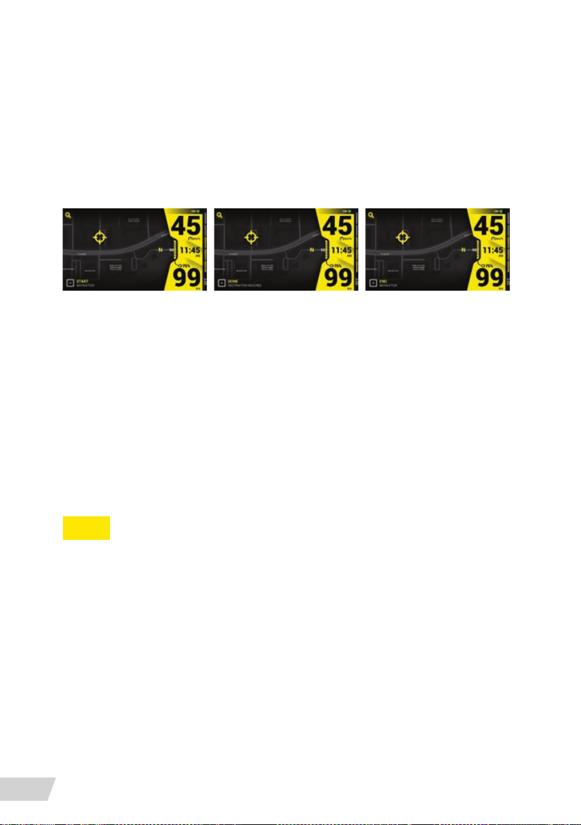
NAVIGATION
You can start/end navigation on the bike using the CBC joystick. The current location is al-
ways available on the map and navigation offers the following:
» Select / Choose Destination
» When the user starts typing the address, a drop-down list of
returned address results should be displayed
» Tap on the map to set the destination
View
» Zoom in/out (Pinch 2 or more ngers
together or apart to adjust zoom)
» Standard/satellite by using Joystick UP/DOWN
Ride info
» Junction direction
» Distance to the next junction
» Trip time
» Trip distance
54
NOTE
DASHBOARD
With unplugging the USB, the navigation will run in the background for an additional 120 sec-
onds. If the user doesn’t plug in the USB within 120 seconds, the navigation session ends.
Page 57
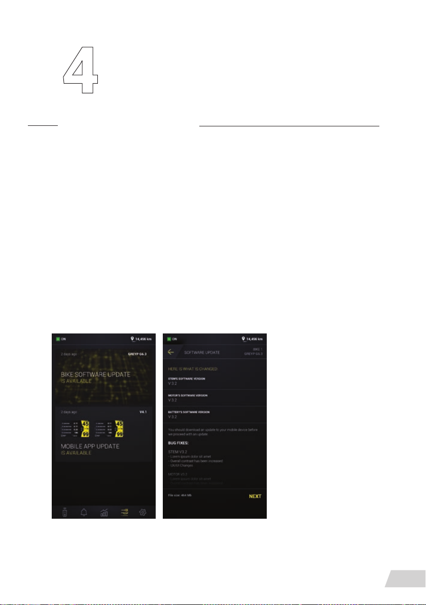
Software update
Software Update is a free service for all Greyp users who want to keep their application up-todate with new functions and better performance using OTA (Over-the-Air).
It’s a very efcient way to upgrade software, x bugs, update or change interface etc. wirelessly for mobile phones and bike components.
How to check for software updates on your Android device
» Expect to get a push notication on your mobile phone
» Head into your Greyp mobile app
» Within the tab bar, select Feed and choose between Mobile app
and/or Bike software update
» Mobile app update will provide a link directly to Play store
» Bike software update will guide you throughout the steps
You will nd all the necessary information about the update and get a link to update your
software to the latest version.
SOFTWARE UPDATE
55
Page 58
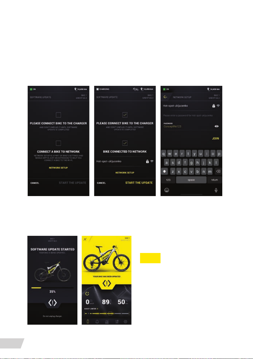
Before you start a software update, there is something you need to do in order to get started.
» Connect the bike to the charger
» Connect the bike to network
Once all these conditions are met, the bike will conrm and enable the next step.
If the network hasn’t been set up earlier, if the login credentials have been changed or if you want
to choose a different access point, please do so now otherwise you won’t be able to proceed.
Once you start the software update, you’ll be guided through the steps needed to achieve it.
If everything goes as expected, you’ll get a notication as shown below. Otherwise, you’ll be
instructed what to do. Please proceed accordingly.
NOTE
When disconnected from the USB-C cable,
the app turns into a remote control system:
send your bike text messages, check the
charge level, adjust the support modes, re-
mote camera access to see what’s going on
around the bike when you’re not there, an
alarm that’s triggered as soon as the bike is
moved, and a kill-switch to completely shut
the bike down if someone has stolen it.
SOFTWARE UPDATE
56
Page 59

SINCE WE ARE CONSTANTLY WORKING
ON IMPROVING USER EXPERIENCE YOU CAN
EXPECT FREQUENTLY MOBILE APP UPDATES.
YOU CAN FIND THE LATEST VERSION OF
THE MANUAL ON OUR WEBSITE
WWW.GREYP.COM
Page 60
Greyp Bikes d.o.o.
Ljubljanska 7
10431 Sveta Nedelja
Croatia
Tel: +385 1 409 3377
Fax: +385 1 333 6698
 Loading...