

Page 1
USER'S GUIDE
Installation & Operation
Instructions
Transit Time Flow Meter
Model TTFM 6.1
www.greyline.com
Manual Series A.1.6
Page 2

Note: This page has been left blank intentionally.
Page 3

TTFM 6.1 Transit Time Flow Meter
INDEX
CONNECTIONS ...................................................................................................................................... 4
KEYPAD SYSTEM .................................................................................................................................. 6
MENU SYSTEM ...................................................................................................................................... 7
ICONS ...................................................................................................................................................... 8
MESSAGE ICON ..................................................................................................................................... 9
STATUS ................................................................................................................................................... 9
PASSWORD ........................................................................................................................................... 11
MENU SELECTIONS ............................................................................................................................ 11
UNITS/MODE ........................................................................................................................................ 12
SET UP ................................................................................................................................................... 14
CALIBRATION ..................................................................................................................................... 17
RELAY PARAMETERS ........................................................................................................................ 19
DATA LOGGING .................................................................................................................................. 20
COMMUNICATION (OPTIONAL) ...................................................................................................... 22
SPECIAL FUNCTIONS ......................................................................................................................... 24
TYPICAL SENSOR INSTALLATION .................................................................................................. 27
SENSOR MOUNTING ........................................................................................................................... 30
2 OR 4 CROSS INSTALLATION OVERVIEW - TMK-B1 KIT .......................................................... 31
1 CROSS INSTALLATION OVERVIEW – TMK-B1 KIT ................................................................... 35
2 OR 4 CROSS INSTALLATION OVERVIEW - TMK-B21 OR TMK-B22 KIT ................................ 42
1 CROSS INSTALLATION OVERVIEW – TMK-B21 OR TMK-B22 KIT ........................................ 46
SENSOR MOUNTING/COUPLING RECOMMENDATIONS ............................................................ 53
ENCLOSURE INSTALLATION ........................................................................................................... 54
FIELD TROUBLESHOOTING .............................................................................................................. 55
COMMON QUESTIONS AND ANSWERS .......................................................................................... 58
APPLICATIONS HOTLINE .................................................................................................................. 60
PRODUCT RETURN PROCEDURE .................................................................................................... 60
SPECIFICATIONS ................................................................................................................................. 64
APPENDIX A - CONVERSION TABLE .............................................................................................. 65
PIPE CHARTS ........................................................................................................................................ 66
APPENDIX C – LIQUID SPEED OF SOUND ...................................................................................... 71
APPENDIX D ......................................................................................................................................... 78
IMPORTANT NOTE: This instrument is manufactured and calibrated to meet product specifications. Please read this
manual carefully before installation and operation. Any unauthorized repairs or modifications may result in a suspension of
the warranty. If this product is not used as specified by the manufacturer, protection may be impaired.
Available in Adobe Acrobat pdf format
Page 3
Page 4

TTFM 6.1 Transit Time Flow Meter
CONNECTIONS:
POWER INPUT: The standard model requires AC power input between 100 to 240 VAC 50/60Hz
10VA. No adjustments are necessary for voltages within this range. Connect L (Live) N (Neutral) and
AC Ground.
Optional DC input model requires 9-32 VDC/10 Watts. Connect to + and - terminals.
Optional Thermostat and Heater modules are available rated for specifically 115 VAC or specifically
230 VAC.
IMPORTANT NOTE: To comply with electrical safety standards, AC power input and relay connection
wires must have conduit entry to the instrument enclosure. Installation requires a switch, overcurrent
fuse or circuit breaker in the building (in close proximity to the equipment) that is marked as the
disconnect switch.
Risk of electric shock. Loosen cover screw to access connections. Only qualified personnel
should access connections.
Note: Use of instrumentation over 40°C ambient requires special field wiring.
Note: Some models feature a user replaceable fuse. Fuse is 2 Amp 250V (T2AL250V), located on the
power supply.
Page 4
Page 5
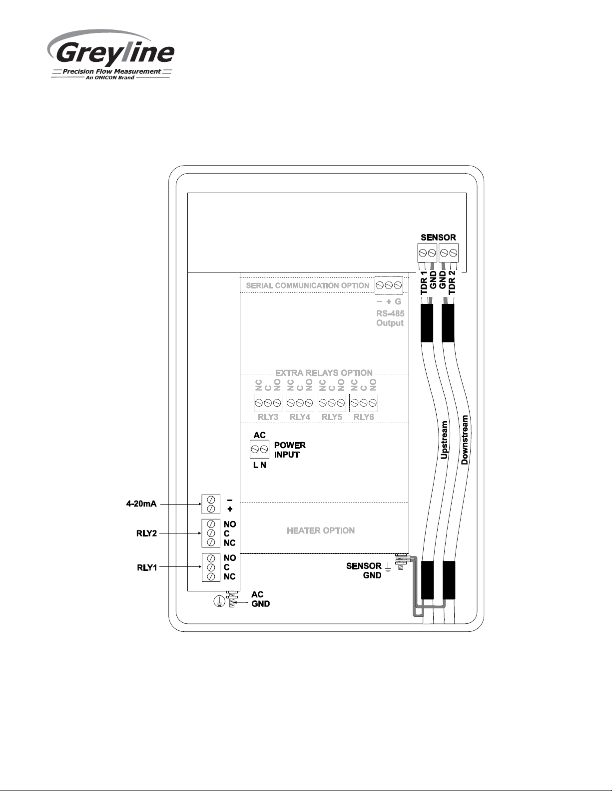
100-240 VAC Meter CONNECTIONS
TTFM 6.1 Transit Time Flow Meter
Page 5
Page 6
TTFM 6.1 Transit Time Flow Meter
KEYPAD SYSTEM
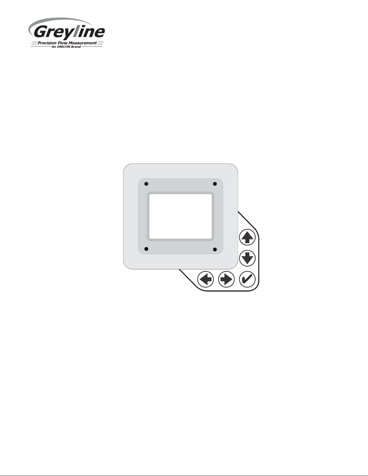
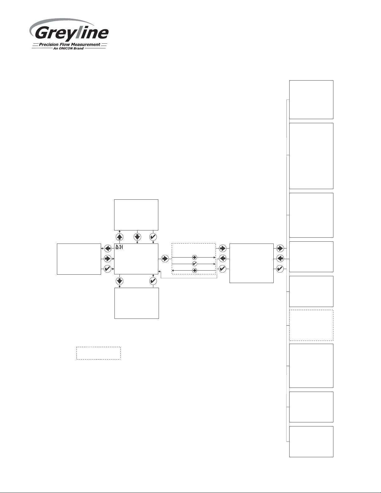
The diagram on page 7 shows the TTFM 6.1 menu system. Arrows show the four directions to leave a
menu box. Pressing a corresponding keypad arrow will move to the next item in the direction shown.
Move the cursor (highlighted) under numerals and increase or decrease numerals with the and
keys.
To store calibration values permanently (even through power interruptions), press the button.
Page 6
Page 7
--24 hr log----------
USG/m
BPS 9600
-- -------
%
4.00 USG/m
emperature
Date Feb. 12/20
10
Total 50138 USG
34.82 USG/m Average
52.20 USG/m Maximum
11:08:00 Max Time
0.000 USG/m Minimum
9:15:00 Min Time
--Messages---------L Data og Logging
dLog Use 0.00000%
Sensor Good
0.00
Tot 20130 USG
Relays 1 2 3 4 5 6
--Status------------
Velocity ft/s
0.00
Flow 0.00 USG/m
Min Flow 4.00 USG/m
Signal Strength 100%
Exp. SOS 4900 ft/s
Meas. SOS 4900 ft/s
MENU SYSTEM
*
--Password----------
Password 0000
TTFM 6.1 Transit Time Flow Meter
--Units/Mode-------Mode Flow
Linear in
Volume USG
Multiplier x1
Decimal 0s
Velocity ft/s
Flow USG/m
Decimal 2s
T F
Setup------
r SE16B
Senso
--Menu-------------Units / Mode
Setup
Calibration
Relay Parameters
Data Logging
Communication
Special Functions
Simulation
Configuration
Angle 37
Fluid Water
Temp Mode Fixed
Temp 77.0 F
Pipe PVC
OD 4.5000 in
Wall 0.2500 in
Lining None
Crossings 2
Zero Tare No
Sens Space 2.299in
Velocity 0.00 ft/s
Signal
Strength
100
--Calibration------Mode Flow
20mA 500.00 USG/m
4mA 0.00 USG/m
LOS Time 10 sec
Min Flow
Damping
Mode FIR
Percent 10%
Window 1.0 ft/s
Cal Constant 1.00
--Relay Parameters--
Relay 1
Function Flow
On 1000 USG
Off 0.000 USG
--Data Logging-------
Log Site ID 01
Mode Flow
File Format .LG2
Date 6 7Jun 2 /201
Time 12:28:41
Interval 30sec
Data Log Logging
--Communication-----
Protocol Modbus
Address 001
Parity Even
Stop Bits 1
°
optional features
* Menu only appears if "New Password" has been
changed from 0000 in "Special Functions" menu.
Page 7
--Special Functions-
Language English
Analog Out 4-20mA
Backlight High
Reset Totalizer NO
Neg. Totals NO
Rev. Flow OFF
Capture Par NO
Capture WF NO
Restore Defaults NO
New Password 0000
--Simulation--------
Test Actual
Flow /m 250USG
Flow 4-20mA 5.60mA
Relays 1 2 3 4 5 6
--Configuration-----
Serial# 12345
Utility 1.25.0 .16
1. Transit Time 38.1
CommBoard 1. . 21 19
Relays 2
Analog Out 1
Page 8
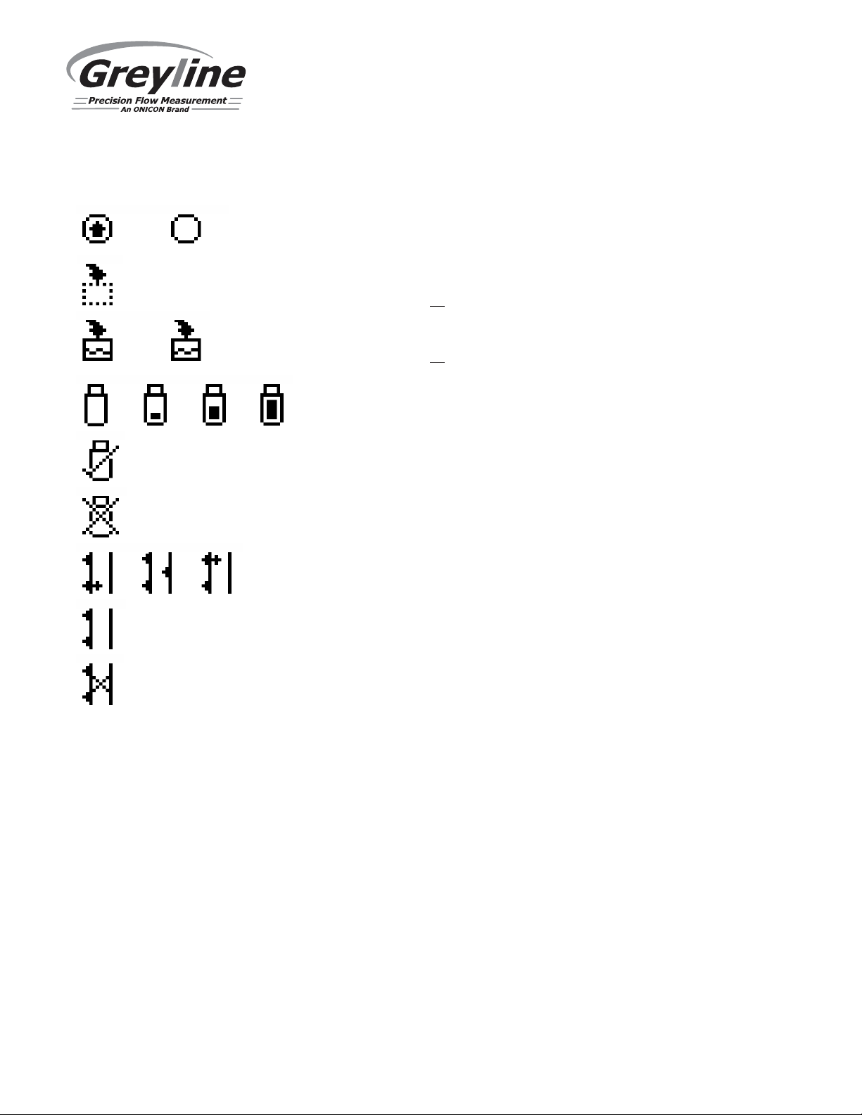
ICONS
TTFM 6.1 Transit Time Flow Meter
1.
1.
1.
1.
2.
2.
2.
2.
3.
3.
4. USB file download .ing
Message waiting. Press . from main page to view
Data logging .off
Data logging .on
File download completed.
Download Error.
TTFM Echo OK.
TTFM - , Empty Pipe .Low Signal / No Echo or high Aeration
TTFM - No Sensors Attached / Wrong Settings
Page 8
Page 9
TTFM 6.1 Transit Time Flow Meter
USG/m
0.00
Tot 20130 USG
Relays 1 2 3 4 5 6
--Status-----------Velocity ft/s 0.00
Flow 0.00 USG/m
Min Flow 4.00 USG/m
Signal Strength 100%
Exp. SOS 4900 ft/s
Meas. SOS 4900 ft/s
MAIN DISPLAY
The Main Display shows the units selected from the Units/Mode menu, flow rate
or velocity rate being measured, totalizer, totalizer multiplier, and relay states. The
TTFM 6.1 will go to this display after start-up.
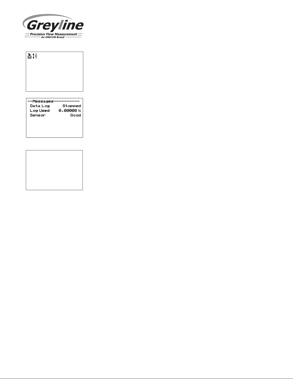
MESSAGE ICON
Press from the Main Display to view status of the data logger and
error/warning messages provided by the instrument. The Message Icon will
appear on the Main Display if error messages are being generated by the
instrument. Press to return to the Main Display.
STATUS
Press from the Main Display to view Status of the measurement. Press to
return to the Main Display.
Velocity Displays flow velocity in ft/s or m/s, selected in the
Units/Mode menu.
Flow Displays flow rate in units selected in the Units/Mode
menu. A list of flow rate units is provided in the
Units/Mode section of the manual.
Min Flow Displays a read-only value for the minimum flow cutoff,
in units which match the Flow selection. Measured flow
rates below the Min Flow will result in the displayed
flow rate on the LCD display to be 0.0. This parameter is
used to suppress electrical noise at zero flow conditions,
and it is typically set to the flow rate equivalent of 0.1
ft/sec in the programmed pipe size. The Min Flow can be
adjusted in the Calibration menu.
Signal Strength Displays magnitude of signal being received by the
ultrasonic sensors. 100% is the ideal signal strength.
Signal strengths less than 100% could indicate poor pipe
conditions (corrosion), highly aerated water, or
programmed setup parameters which don’t closely
match field conditions. Consideration should be made to
use 1-cross installation method in such cases, if not
already using it.
Page 9
Page 10
Status (cont.)
TTFM 6.1 Transit Time Flow Meter
--Status-----------Velocity ft/s 0.00
Flow 0.00 USG/m
Min Flow 4.00 USG/m
Signal Strength 100%
Exp. SOS 4900 ft/s
Meas. SOS 4900 ft/s
Exp. SOS Displays the expected fluid speed of sound
measurement, in units that match the Velocity. The
expected speed of sound is based on the pipe, fluid, and
temperature selection in the Setup menu.
Meas. SOS Displays the measured fluid speed of sound, in units that
match Exp. SOS. The meter calculates this value based
on the time it takes for the signal to arrive from one
transducer to another. Large differences between
expected and measured speed of sound (> 10%) typically
indicate an error in the setup of the instrument. Verify
the following are correct in the Setup menu and with the
physical installation of the transducers:
- Pipe Material
- Pipe OD
- Pipe Wall Thickness
- Liner Type
- Liner Thickness
- Fluid Type
- Fluid Temperature
- Crossings
- Separation Distance
Page 10
Page 11
TTFM 6.1 Transit Time Flow Meter
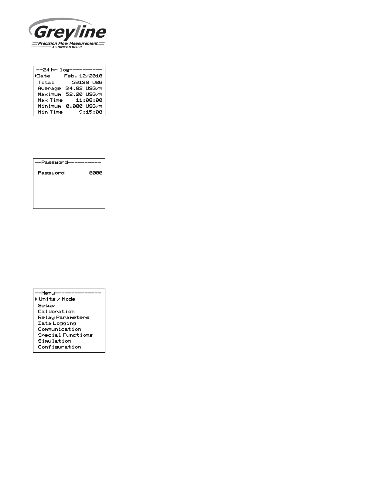
24 HR LOG
Press from the Main Display to view a formatted flow report. Press to scroll
down one day or repeatedly to scroll to a specific date. Up to 365 days will be
stored. Newest date will overwrite the oldest. Press to return to the Main
Display.
IMPORTANT: Inserting a USB drive into the meter while on this screen will
transfer 24 HR Log data to the USB drive in .csv format.
PASSWORD
The Password (a number from 0000 to 9999) prevents unauthorized access to the
Calibration menu.
From the Main Display press the key to get to Password. Factory default
password is 0000 and if it has not been changed, this screen will be bypassed
completely.
A new password can be stored by going to the Special Functions New
Password menu.
If a user password is required, press to place the cursor under the first digit and
or to set the number, then to the second digit, etc. Press or to proceed
to the Menu Selections screen.
MENU SELECTIONS
The Menu selections page is used to navigate to specific menus which are
described in more detail on the following pages.
Press or to navigate to different menus, and to enter the selected menu.
Page 11
Page 12
store your selection then the
to the next menu
item
.
next menu item.
as an example. Press
to store your selection then
to the next menu i
tem.
menu item.
selection then
to the next menu item.
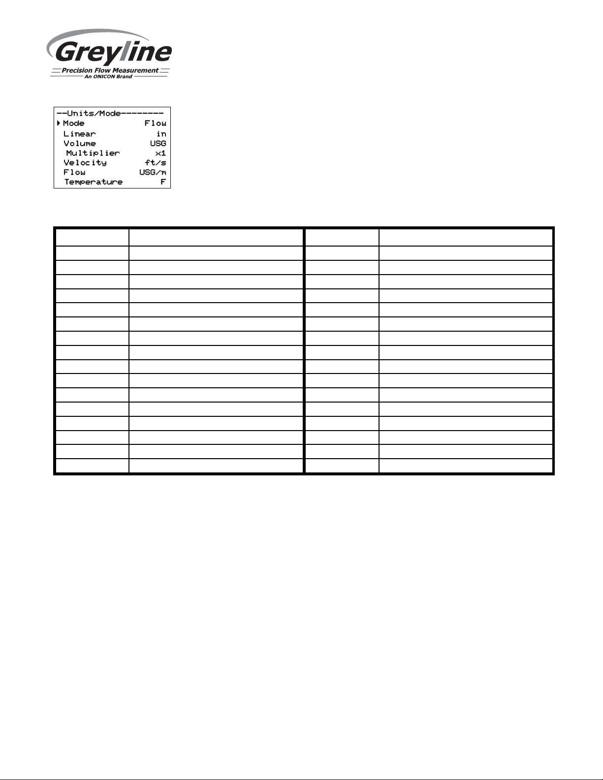
--Units/Mode-------Mode Flow
Linear in
Volume USG
Multiplier x1
Decimal 0s
Velocity ft/s
Flow USG/m
Decimal 2s
emperatureT F
TTFM 6.1 Transit Time Flow Meter
UNITS/MODE
At Mode, press the and then the or to select Flow or Velocity. Flow
mode displays the flow rate in engineering units (e.g. gpm, litres/sec, etc.) Press
the to store your selection then the to the next menu item.
At Linear press the key and then the or to select your units of
measurement. The Linear units define what units the pipe dimensions and sensor
spacing will be displayed in. Typically inches or mm is selected. Press the to
At Volume, press the and then the or to select units for volume. Note:
“bbl” denotes US oil barrels. Press the to store your selection then the to the
At Multiplier, press the and then the or to select the totalizer
multiplier. Multipliers are used when resolution down to single digit is not
required, or when you don’t want to convert from gallons to thousands of gallons,
At Decimals (Volume), press the and then the or to select the number
of decimal points to be present on the totalizer display on the LCD screen. Default
= 0. Options = 0, 1, 2. Press the to store your selection then the to the next
At Velocity, press the and then the or to select the engineering
units for flow velocity and sonic velocity of the fluid. Press to store your
Page 12
Page 13
TTFM 6.1 Transit Time Flow Meter
menu item
, orto
exit back to the Menu Selection screen
.
UNITS/MODE (cont.)
At Flow, press the and then the or to select the engineering units for
flow rate. Press to store your selection then to the next menu item.
Available Flow Rate Engineering Units:
Abbreviation Description Abbreviation Description
USG/d US gallons per day L/d liters per day
USG/h US gallons per hour L/h liters per hour
USG/m US gallons per minute L/m liters per minute
USG/s US gallons per second L/s liters per second
ft3/d cubic feet per day m3/d cubic meters per day
ft3/h cubic feet per hour m3/h cubic meters per hour
ft3/m cubic feet per minute m3/m cubic meters per minute
ft3/s cubic feet per second m3/s cubic meters per second
bbl/d barrels per day (1 bbl = 42 USG) IG/d Imperial gallons per day
bbl/h barrels per hour (1 bbl = 42 USG) IG/d Imperial gallons per day
bbl/m
bbl/d
USMG/d US million gallons per day IMG/d Imperial million gallons per day
USMG/h US million gallons per hour IMG/h Imperial million gallons per hour
USMG/m US million gallons per minute IMG/m Imperial million gallons per minute
USMG/s US million gallons per second IMG/s Imperial million gallons per second
barrels per minute (1 bbl = 42 USG)
barrels per second (1 bbl = 42 USG)
IG/d Imperial gallons per day
IG/d Imperial gallons per day
At Decimals (Flow), press the and then the or to select the number of
decimal points to be present on the flow rate display on the LCD screen. Default =
2. Options = 0, 1, 2. Press the to store your selection then the to the next
menu item.
At Temperature, press the and then the or to select units for
temperature. Press the to store your selection then the to go back to another
Page 13
Page 14
TTFM 6.1 Transit Time Flow Meter
-- -------Setup-----r SE16B Senso
Angle 37°
Fluid Water
Temp Mode Fixed
Temp 77.0 F
Pipe PVC
OD 4.5000 in
Wall 0.2500 in
Lining None
Crossings 2
Zero Tare No
Sens Space 2.299in
Velocity 0.00 ft/s
Signal
Strength100%
SET UP
Press or to position curser at Setup, and to enter. Use or to position
cursor before each menu item and to enter. When settings are completed press
to store and again to return to the Main Menu.
Sensor
Select
Angle
Choose SE16B.
Select angle which matches the transducer pair connected to the
TTFM. Options: 35, 37, 39, and 41.
Angle is determined by the part number on the SE16-B
transducer label. Guide:
Part Number on SE16-B Label Corresponding Transducer Angle
SE16-B-35 35
SE16-B-37 37
SE16-B-39 39
SE16-B-41 41
Fluid
Vel@25C
Select fluid type.
When Fluid = Other, enter the fluid velocity at 25C from table or
other reference. Engineering units may be m/s or ft/s depending
on Units menu programming.
dV/C
Temp Mode
Temp
Pipe
Pipe Vel
OD
Wall
When Fluid = Other, Enter fluid velocity adjustment factor over
change in temperature in units of m/s or ft/s per °C.
Choose Fixed.
Enter fluid operating temperature in displayed engineering units.
Select pipe material.
When Pipe = Other, enter pipe material speed of sound (consult
factory).
Highlight the digits and then or to change the numbers and
decimal point. Pipe OD should be entered as the exact outside
diameter of the pipe where the sensor is mounted. Refer to the
Pipe Charts Appendix in this manual for outside diameter of
common pipe types and sizes.
Enter pipe wall thickness. Pipe wall thickness should be entered
as the exact wall thickness of the pipe where the sensor is
mounted. Refer to the Pipe Charts Appendix in
this manual for wall thicknesses of common pipe types and
sizes.
Lining
Select liner material.
Page 14
Page 15
TTFM 6.1 Transit Time Flow Meter
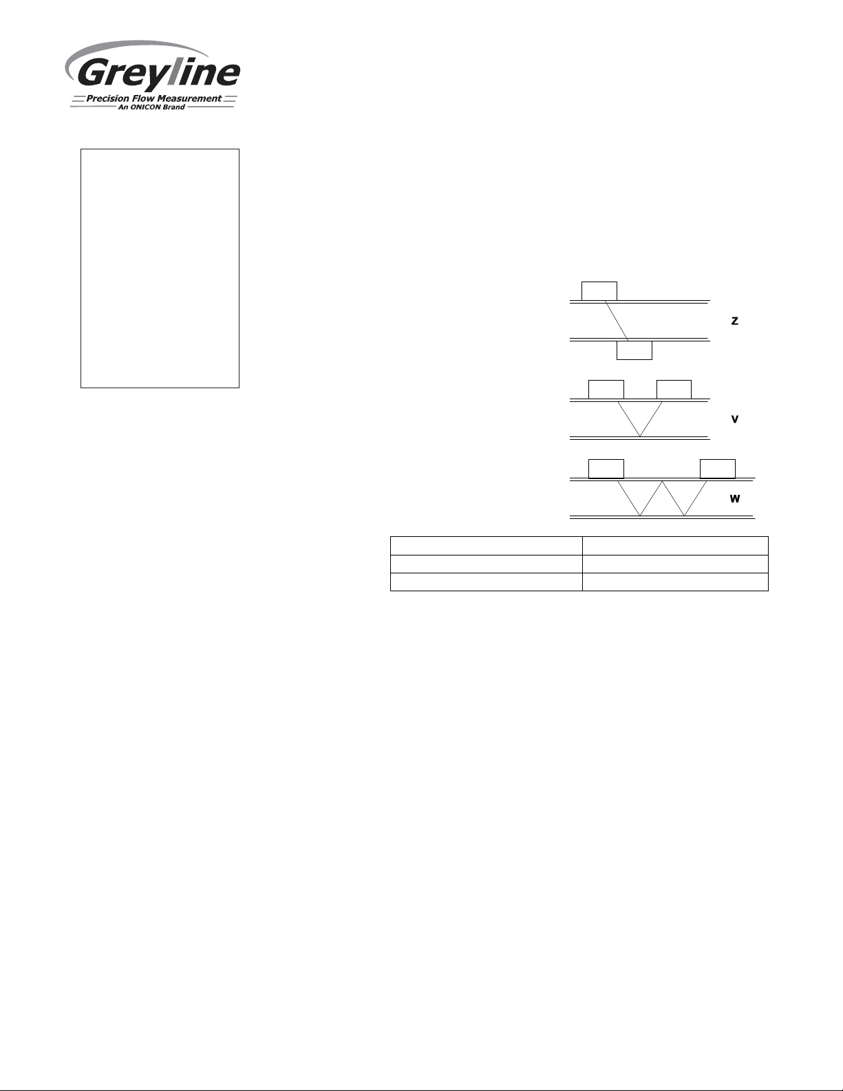
2-24
Crossings = 2
> 24Crossings = 1
= 1 in cases such as these.
-- -------Setup-----r SE16B Senso
Angle 37°
Fluid Water
Temp Mode Fixed
Temp 77.0 F
Pipe PVC
OD 4.5000 in
Wall 0.2500 in
Lining None
Crossings 2
Zero Tare No
Sens Space 2.299in
Velocity 0.00 ft/s
Signal
Strength100%
SET UP (cont.)
Vel
Thick
Crossings
When Lining = Other, enter speed of sound of liner (consult
factory).
When Lining ≠ None, enter liner thickness.
Crossings 1 = Z mounting
Crossings 2 = V mounting
Crossings 4 = W mounting
Nominal Pipe Size, Inches Recommended Crossings
Zero Tare
Sens Space
Velocity
Older pipes are often degraded or scaled on the inside. These
conditions can hinder the ability to receive a strong signal
when Crossings = 2. Greyline suggests starting with Crossings
Used to calibrate zero-flow measured by the TTFM 6.1 in
process. Flow in the pipe should be confirmed as 0 before
enabling, or significant errors in flow accuracy could occur.
Set Calibration/Damping to 0%, and under no flow conditions
and with a full pipe, select Yes to force readings to zero.
After sensor, angle, fluid, and pipe material are defined, this
displays the calculated sensor spacing. Also called the
separation distance. The sensors will be set to this dimension
when installed on the pipe, as described later in this manual.
Displays the measured velocity after the sensors have been
connected at the specified separation distance.
Page 15
Page 16
TTFM 6.1 Transit Time Flow Meter
-- -------Setup-----r SE16B Senso
Angle 37°
Fluid Water
Temp Mode Fixed
Temp 77.0 F
Pipe PVC
OD 4.5000 in
Wall 0.2500 in
Lining None
Crossings 2
Zero Tare No
Sens Space 2.299in
Velocity 0.00 ft/s
Signal
Strength100%
SET UP (cont.)
Signal
Strength
Displays magnitude of signal being received by the ultrasonic
sensor. Should be 100% under ideal operating conditions.
Signal strengths less than 100% do not indicate that the meter
is not reliable, however, the meter may be more susceptible to
complete signal loss should process conditions like entrapped
air worsen. When signal strength is less than 100%,
consideration should be made to using 1-cross mounting
method if this is not the current mounting mode.
Page 16
Page 17
TTFM 6.1 Transit Time Flow Meter
--Calibration------Mode Flow
20mA 500.00 USG/m
4mA 0.00 USG/m
LOS Time 10 sec
Min Flow 4.00 USG/m
Damping
Mode FIR
Percent 10%
Window 1.0 ft/s
Cal Constant 1.00
CALIBRATION
Press or to position curser at Calibration menu, and to enter. Use or
to position cursor before each menu item and to enter. When settings are
completed press to store and again to return to the Main Menu.
Mode
Displays the Mode which was selected in the Units/Mode
menu. This is read-only.
20mA
Press then or to change the numbers and decimal point
position. Use this menu to set the corresponding flow rate that
will be represented by 20mA analog output. If maximum flow
is unknown, enter an estimated flow rate and observe actual
flow to determine the correct maximum value. Any velocity or
flow rate up to +40 ft/sec (12.0 m/sec) may be selected.
4mA
Press then or to set the flow rate corresponding to
4mA analog output. This setting may be left at zero or can be
raised to any value less than the 20mA setting, or lowered to
any velocity or corresponding flow rate down to -40 ft/sec (-12
m/sec).
LOS Time
Use LOS Time to suppress intermittent loss of signal.
Example: systems with high concentrations of undissolved
gasses will cause fluctuations in signal strength when the
gasses move past the ultrasonic signal. If a complete loss of
signal is experienced, the TTFM 6.1 will hold the last valid
reading for the duration of the LOS Time. If the signal strength
returns before the LOS Time is expired, because the ultrasonic
signal is no longer being impeded, the meter will return to
normal operation automatically. If signal strength does not
return after the LOS Time has expired, then the meter will
report zero flow on the LCD display and outputs, and produce
a Low Signal alarm. Default LOS Time is 30 seconds, and the
value can be set between 0 and 99 seconds.
Min Flow
Flow rates below this setting will be displayed as zero flow.
Default flow rate is 0.1 ft/sec for the pipe size programmed
in the Setup menu.
Page 17
Page 18
TTFM 6.1 Transit Time Flow Meter
av
erage, both the FIR and LOW PASS filter behave the same.
--Calibration-------
Mode Flow
20mA 500.00 USG/m
4mA 0.00 USG/m
LOS Time 10 sec
Min Flow 4.00 USG/m
Damping
Mode FIR
Percent 10%
Window 1.0 ft/s
Cal Constant 1.00
CALIBRATION (cont.)
Damping
Mode
Choose between OFF, FIR (Default), or LOW PASS.
When measured flows are outside the Window of the running
average, the FIR filter will reduce the damping average so that
a fast response can be made to the sudden change in flow rate.
The LOW PASS filter will ignore measured flow rates outside
the Window, while holding the running average, until there are
enough data points outside the Window to cause a stepresponse to the new measured value.
While measured flows are within the Window of the running
Percent
Higher percentages increase the number of measurements
which are averaged together to produce a stable flow reading.
Higher percentages also increase the time it takes for the meter
to make a step-response to the measured flow rate outside the
Window in the LOW PASS Mode.
Window
Defines the Window around the running average, in units of
Velocity set in the Units/Mode menu. Measurements made
inside the Window are added to the running average, and
measurements outside the Window effect the response of the
meter as described in the Mode section.
Cal
Constant
Calibration constant defined when the TTFM was calibrated at
the Greyline factory.
Press to return to Menu Selections.
Page 18
Page 19
TTFM 6.1 Transit Time Flow Meter
or
for this to work properly.
--Relay Parameters--
Relay 1
Function Flow
On 1000 USG
Off 0.000 USG
RELAY PARAMETERS
Press or to position curser at Relay Parameters, and to enter. Use or
to position cursor before each menu item and to enter. When settings are
completed press to store and again to return to the Main Menu.
Relay
Press and or to select a corresponding relay number
(2 relays are standard, 4 additional are optional).
Function
Pulse
Press or to select Off, On, Pulse,
Direction, or Flow.
Press and set digits to the flow volume increment required
between relay pulses. Use this feature for remote samplers,
chlorinators or totalizers. Minimum time between pulses is
2.25 seconds and pulse duration is 350 milliseconds.
Return to Relay and change settings for each relay
number.
Press to return to Menu Selections.
Direction
When flow is in the positive direction, the relay will be
disengaged, when flow is negative, the relay engages.
Note: Rev. Flow in the Special Functions menu must be ON
INVERT
Flow
Mode Select Pump
Pump mode provides separate On/Off settings where the
relay will energize at one flow rate and de-energize at
another.
On Highlight the numerals and press or to set digits to
the required relay On set point.
Off set digits to the required Off set point.
Page 19
Page 20
TTFM 6.1 Transit Time Flow Meter
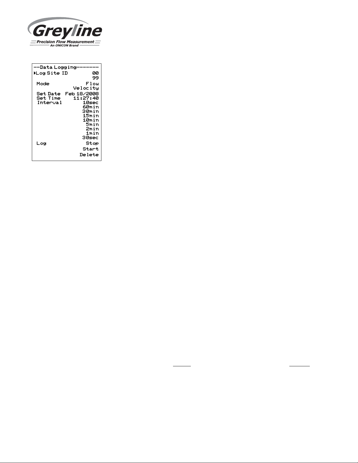
DATA LOGGING
Press or to position curser at Data Logging, and to enter. Use or to
position cursor before each menu item and to enter. When settings are
completed press to store and again to return to the Main Menu.
Log Site ID Enter a number from 00 to 99. The site ID will become part of
the downloaded file name to help distinguish downloads from
different instruments. Press to store the setting.
Mode Select Velocity (e.g. ft/sec or m/sec) or Flow (e.g. USGPM or
l/sec). Press to store the setting. This setting cannot be
changed after a log was started. To change, first stop the log,
then change the mode.
File Format Choose .LG2 to download data in .lg2 format for viewing on
Greyline Logger software. Choose .CSV to download data in
.csv format for import directly to Excel. This menu option can
be changed at any time without adversely affecting existing
data.
Date Press , and or to scroll and select Month, Day and
Year. Press to store the setting.
Time Press , and or to select the current time in Hours,
Minutes and Seconds. Press to store the setting.
Interval Press or to select the logging interval. Press to store
the setting. Greyline recommends choosing an interval which
will give you as much resolution as required and no more.
Choosing too often of an interval for what is required will
result in larger data files, which may take a long time to
download to USB. Reference page 18 for specific download
times. In critical installations, data should be downloaded
often.
Data Log Stop, Start or Delete the log file. Press or to select Delete
and to delete the log file. Press or to select Start and
to start the logger.
Important Note: You MUST Delete an old log and Start a new log AFTER
having made changes to Log Site ID, Mode, Date, Time and/or Interval for those
changes to be applied.
Important Note: Changing any of the parameters in the Units/Mode menu will
start a new log. It is recommended that you Delete and start a new log after
changing any Units/Mode settings.
Page 20
Page 21
TTFM 6.1 Transit Time Flow Meter
RETRIEVING LOG FILE
Plug a USB Flash Memory Drive (one is included with the TTFM 6.1) into the
USB output port on the Panel of the meter. The instrument display will show the
data download icon until the log file is transferred to the memory card. The USB
flash drive may be removed when the icon for download successful appears.
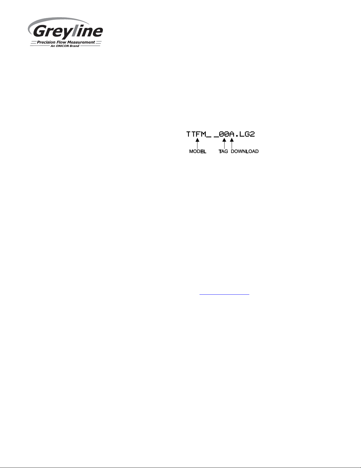
Download file names will appear in this format:
Tag is set according to the Log Site ID entered in the instrument Data
Logging menu.
Download letter will be A for the first download from an instrument. B for the
second, then C etc. At the letter Z a - character will appear indicating that the
maximum number of downloads for that instrument are on the USB flash drive.
Older files can be erased or moved from the flash memory drive or a new memory
drive can be used.
Note: Downloading files in .lg2 format will take approximately 35 seconds per
1% of internal log memory used.
Downloading files in .csv format will take approximately 8 minutes per 1%
of internal log memory used.
OPENING .LG2 FILES
Install Greyline Logger on your PC or laptop. Select File/Open/Instrument Log
(.log) to open the log file from your USB flash drive. Greyline Logger software is
available on Greyline’s website, www.greyline.com. Data can also be converted
to .CSV via Greyline Logger software.
OPENING .CSV FILES
Use a datasheet program such as Microsoft Excel® to import data in a comma
delimited format. Use Excel to manipulate or graph data.
Page 21
Page 22

TTFM 6.1 Transit Time Flow Meter
setting.
COMMUNICATION (Optional)
Press or to position curser at Communication, and to enter. Use or
to position cursor before each menu item and to enter. When settings are
completed press to store and again to return to the Main Menu.
MODBUS Protocol Information:
Transceiver: 2-wire, half-duplex
Data format: 8 Data Bits
Floating Point Byte Order: ABCD
Termination: Jumper JP1 selectable 120Ω resistor. TB1 & TB2 = OFF,
TB2 & TB3 = ON
Biasing: None
HART® (Highway Addressable Remote Transducer) Protocol Information:
HART Version: 7.0
Device
Description
Files:
DD files allow the user’s handheld HART communicator to
fully configure the TTFM 6.1 Greyline provides DD files for
the Emerson 475 Communicator. The files are included in the
USB drive provided with your TTFM 6.1 meter. You may
also request the files from Greyline by calling or emailing us
at [email protected]. Warning: The TTFM 6.1 and
associated DDs are pending certification from the Fieldcomm
Group.
Connections: HART Protocol uses a digital signal superimposed on the 4-
20mA output. When the 4-20mA output of the TTFM 6.1 is
connected with a load resistor (230Ω to 600Ω), the HART
communicator can be connected on the loop in order to
communicate.
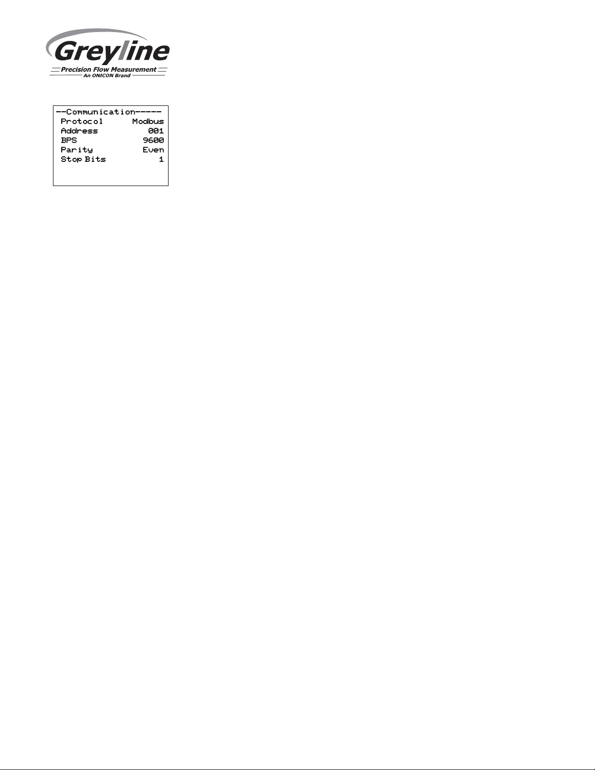
Protocol
Address
(Modbus)
Choose MODBUS or HART.
Device address for the TTFM. Valid range: 001-247 (Default:
001). This number should be unique across the bus. Press
or to scroll, to select digits, and press to store the
Page 22
Page 23
TTFM 6.1 Transit Time Flow Meter
found in separate TTFM 6.1 Serial Communications Manual.
COMMUNICATION (Optional) (cont.)
BPS
(Modbus)
Baud rate for the MODBUS communications. Press or
to select, and to store the setting. Options: 4800, 9600,
19200, 38400, 57600, 76800, and 115200 (Default: 9600).
Parity
(Modbus)
Error checking parity for the MODBUS communications.
Press or to select, and to store the setting. Options:
None, Even, and Odd (Default: Even).
Stop Bits
(Modbus)
Press or to select, and to store the setting. Options: 1
or 2 (Default: 1).
Note: The Modbus register table, and HART configuration instructions can be
Page 23
Page 24
TTFM 6.1 Transit Time Flow Meter
--Special Functions-
Language English
Analog Out 4-20mA
Backlight High
Reset Totalizer NO
Neg. Totals NO
Rev. Flow OFF
Capture Par NO
Capture WF NO
Restore Defaults NO
New Password 0000
SPECIAL FUNCTIONS
Press or to position curser at Special Functions, and to enter. Use or
to position cursor before each menu item and to enter. When settings are
completed press to store and again to return to the Main Menu.
Language
Analog Out
Backlight
Select English, French or Spanish
Select 4-20mA or 0-5V mode for the analog output.
Select High, Medium or Low for continuous
backlight brightness.
Select Key Hi/Lo for high backlight lasting 1
minute after a keypress, and then Lo backlight until
a key is pressed again.
Select Key High, Med or Low for backlight
lasting 1 minute after a keypress and then backlight off
until a key is pressed again.
Reset Totalizer
Select Yes to erase and restart the totalizer at zero.
Negative Totals
Rev. Flow
Capture Par
Select Yes to have reverse flow readings deducted
from the totalizer. Select No to totalize forward flow
only and ignore reverse flow.
Select On to enable flow direction measurement.
Select Off to disable flow direction measurement so
that flow in either direction is displayed and output as
positive values.
Select Invert to invert the sense of the flow
measurement.
This function captures the programming parameters in
the meter. Select Yes, wait for Insrt USB to
appear, then insert a USB drive into the USB port to
transfer the parameters. After Saving flashes, Done
will appear on the screen, meaning it is safe to remove
the USB,
Page 24
Page 25
to be sent to Greyline.
--Special Functions-
Language English
Analog Out 4-20mA
Backlight High
Reset Totalizer NO
Neg. Totals NO
Rev. Flow OFF
Capture Par NO
Capture WF NO
Restore Defaults NO
New Password 0000
SPECIAL FUNCTIONS (cont.)
Capture WF
This function should only be used when instructed by a
Greyline representative to do so. The function captures
the ultrasonic signal so that it can be evaluated by
Greyline.
Select Yes to start the waveform download process.
After pressing Yes , the screen will flash Working
for approximately 20 seconds, until the message
Insrt USB appears. When Insrt USB is on the
screen, connect a flash drive to the USB port on the
front of the meter. The screen will flash Saving for
a couple seconds, and then return to Done . The
waveform is now stored on your flash drive and ready
TTFM 6.1 Transit Time Flow Meter
Restore
Defaults
Select Yes to erase all user settings and return the
instrument to factory default settings. Note: does not
reset factory calibration values.
New Password
Select any number from 0000 to 9999. Default setting
of 0000 will allow direct access to the calibration
menus. Setting any password other than 0000 will
require the password to be entered to access the
calibration menus.
Press to return to Menu Selections.
Page 25
Page 26
TTFM 6.1 Transit Time Flow Meter
screen.
SIMULATION
Press or to position curser at Simulation, and to enter. Use or to
position cursor before each menu item and to enter. When settings are
completed press to store and again to return to the Main Menu.
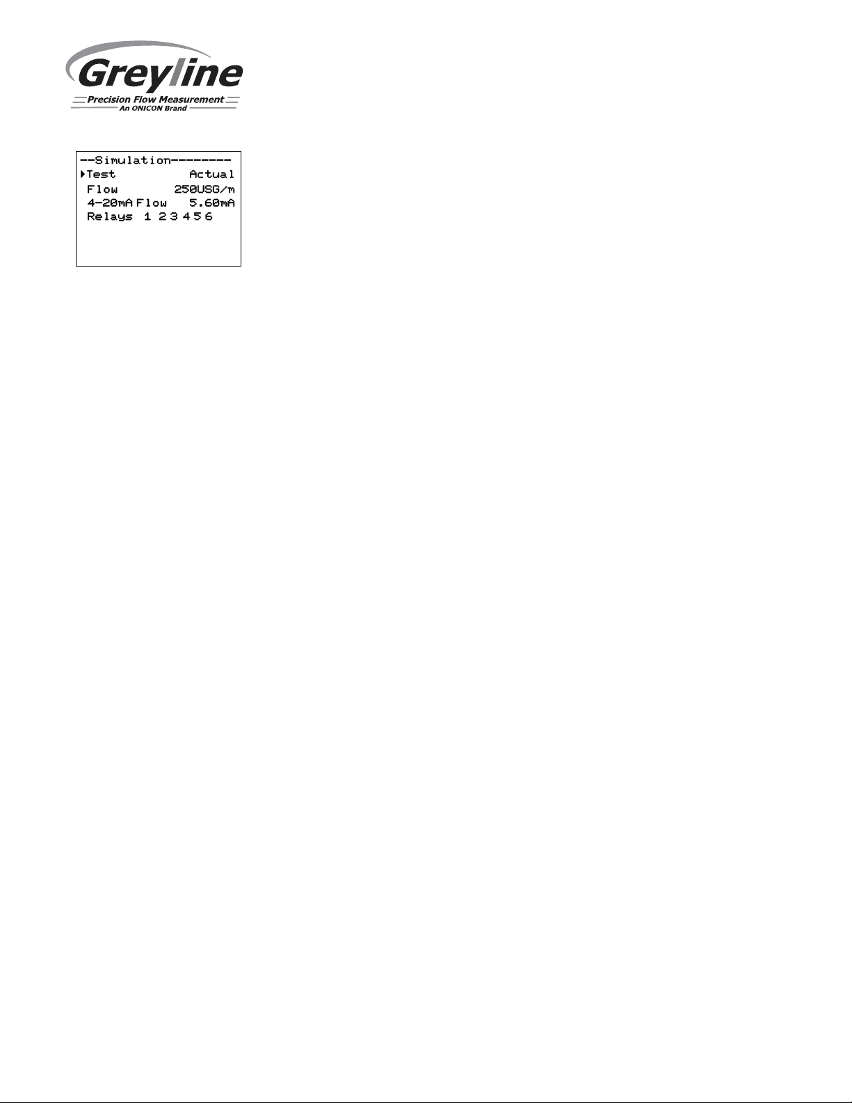
Changes made in the Simulation menu exercise the 4-20mA output, digital display
and control relays.
Simulate a Flow /Velocity reading. Press and then or to change
the simulated output. Press to begin simulation. The 4-20mA output and relay
states will be displayed on the screen below.
Press the to terminate simulation and return to the Menu Selections
Page 26
Page 27
TYPICAL SENSOR INSTALLATION
TTFM 6.1 Transit Time Flow Meter
Page 27
Page 28
TTFM 6.1 Transit Time Flow Meter
Pipe Preparation and Bracket Mounting
Prepare an area 2" wide by 4" long (50mm x 100mm) for each sensor bonding by removing loose paint,
scale and rust. The objective of site preparation is to eliminate any discontinuity between the sensor and
the pipe wall, which would prevent acoustical coupling. A sanding block is included with every meter to
facilitate proper pipe preparation.
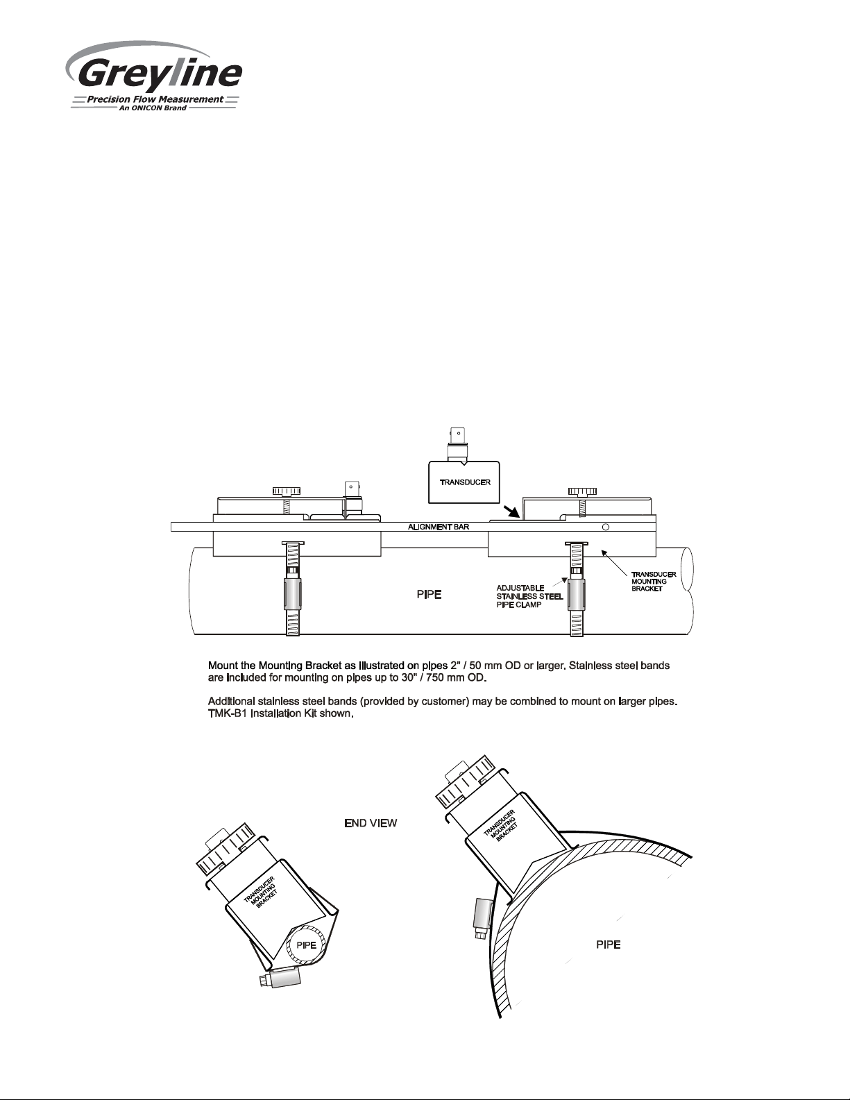
A Sensor Mounting Kit is supplied with each Greyline flow meter. It includes recommended coupling
compound and a stainless steel mounting bracket with adjustable pipe straps. Use the Alignment Bar
(included) to align sensor brackets for V and W mode mounting.
IMPORTANT: The SE16-B transit-time transducers have arrows on the top of them. These should face
each other at installation.
Page 28
Page 29
TTFM 6.1 Transit Time Flow Meter
SENSOR COUPLING
For permanent or temporary bonding, the following are recommended:
a) Super Lube® (supplied)
Additional supply: order Greyline Option CC-SL30 or your local home improvement store.
b) Water-based sonic compound: Order Greyline Option CC30
c) Electrocardiograph gel
d) Petroleum gel (Vaseline)
The above are arranged in their order of preferred application. Option d is only good for temporary
bonding at room temperature. DO NOT USE: Silicon RTV caulking compound (silicon rubber).
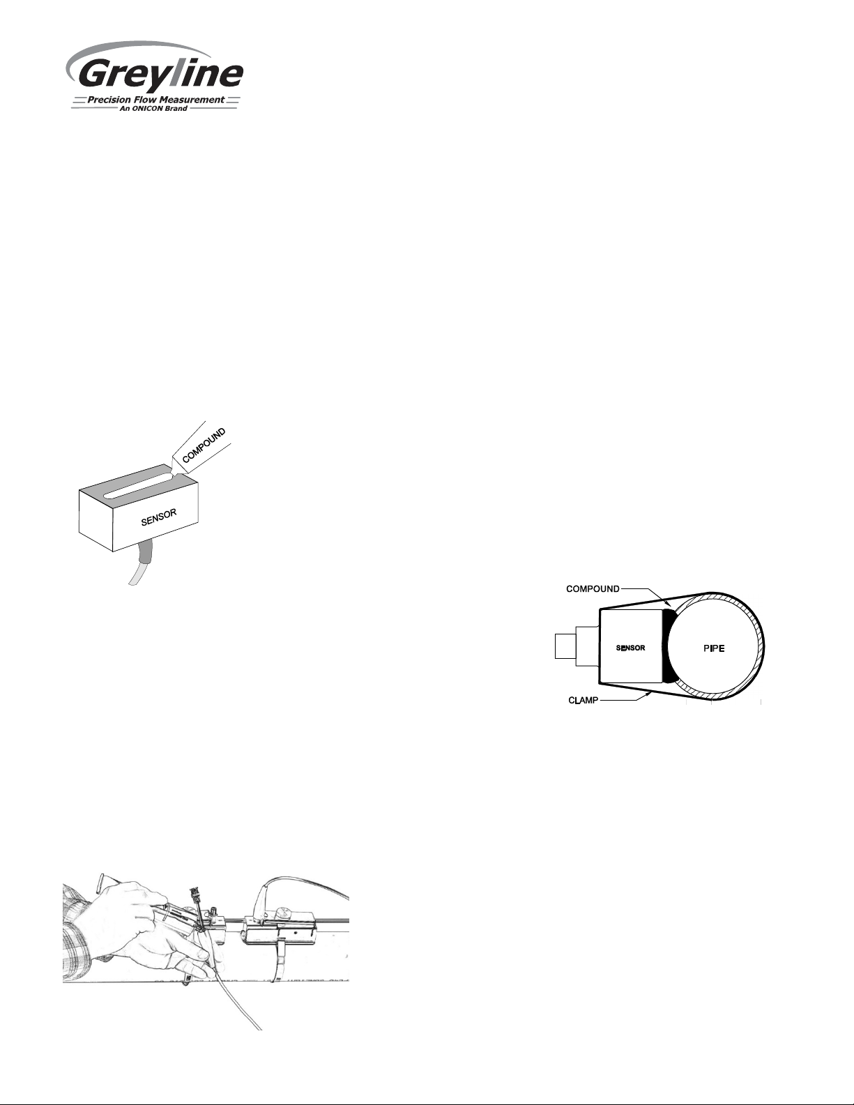
Use the pipe clamp and rail (supplied) as illustrated on previous page. Apply
Super Lube® to the colored face of the sensor. A bead, similar to toothpaste on
a toothbrush, is ideal. Do not overtighten (crush the sensor).
The sensor must be fixed securely to the pipe with coupling material
between the sensor face and the pipe. Sensor installation with
excessive coupling compound can result in gaps or voids in the
coupling and cause errors or loss of signal. Insufficient coupling
compound will create similar conditions.
Over time temporary coupling compounds (e.g. Petroleum Gel) may gradually sag away from the sensor
resulting in reduced signal strength and finally complete loss of signal. Warm temperatures, moisture
and vibration will accelerate this process. Super Lube® as supplied with the TTFM 6.1 (and available
from Greyline Instruments or home improvement stores) is recommended for permanent installations.
Transducer Installation in Wet Locations
The TTFM 6.1 Transit Time Flowmeter transducers are
rated for accidental submersion up to 10 psi (0.75 bar). The
flowmeter will continue to operate and measure flow
accurately during periods of submergence. Plastic seal
jackets on the cables must be filled with coupling compound
to provide additional moisture protection for the BNC cable
connectors.
Page 29
Page 30

TTFM 6.1 Transit Time Flow Meter
SENSOR MOUNTING LOCATION
The position of the sensor is one of the most important considerations for accurate flow measurement.
The same location guidelines apply to Transit Time as most other flow meter technologies.
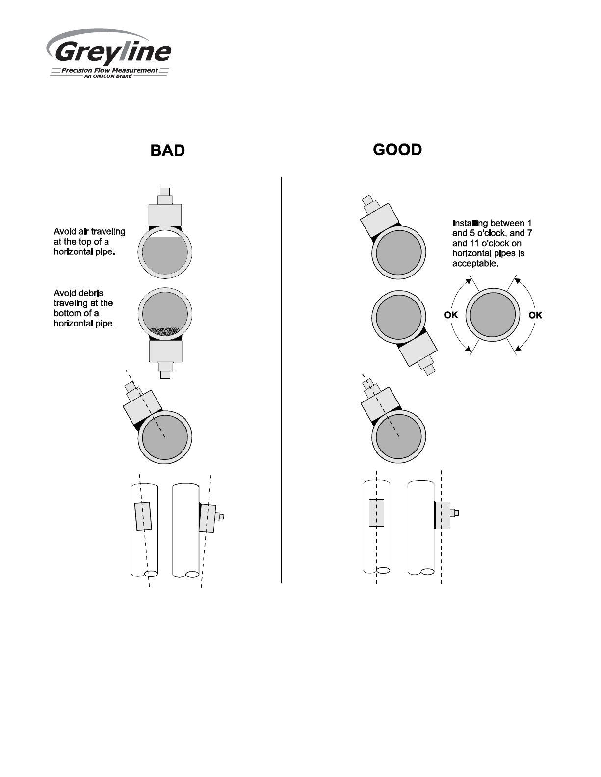
VERTICAL OR HORIZONTAL PIPE - Vertical pipe
runs are acceptable, and the transducers can be
mounted in any orientation around the pipe.
Downward flow should be avoided in case the pipe
becomes partially filled or aerated. On Horizontal
pipes and liquids with high concentrations of gas or
solids, the sensors should be mounted on the side (1 to
5 o’clock positions) to avoid concentrations of gas at
the top of the pipe, or solids at the bottom.
STRAIGHT RUN REQUIREMENTS – For best
results, the transducers must be installed on a straight
run of pipe, free of bends, tees, valves, transitions,
insertion probes and obstructions of any kind. For
most installations, ten straight unobstructed pipe
diameters upstream and five diameters
downstream of the transducers is the minimum
recommended distance for proper operation.
Additional considerations are outlined below.
• Do not, if possible, install the transducers downstream from a throttling valve, a mixing tank, the
discharge of a positive displacement pump or any other equipment that could possibly aerate the
liquid. The best location will be as free as possible from flow disturbances, vibration, sources of heat,
noise, or radiated energy.
• Avoid mounting the transducers on a section of pipe with any external scale. Remove all scale, rust,
loose paint, etc., from the location prior to mounting the transducers. A sanding block is included with
every meter to facilitate proper pipe preparation.
• Do not mount the transducers on a surface aberration (pipe seam, etc.).
• Do not mount transducers from different ultrasonic flow meters on the same pipe.
• Do not run the transducer triaxial cables in common bundles with cables from other instrumentation.
You can run these cables through a common conduit ONLY if they originate at the same flow meter.
• Never mount transducers under water.
IMPORTANT NOTE: In some cases, longer straight runs may be necessary where the transducers are
placed downstream from devices which cause unusual flow profile disruptions or swirl. For example:
modulating valves, or two elbows in close proximity and out of plane.
Page 30
Page 31

TTFM 6.1 Transit Time Flow Meter
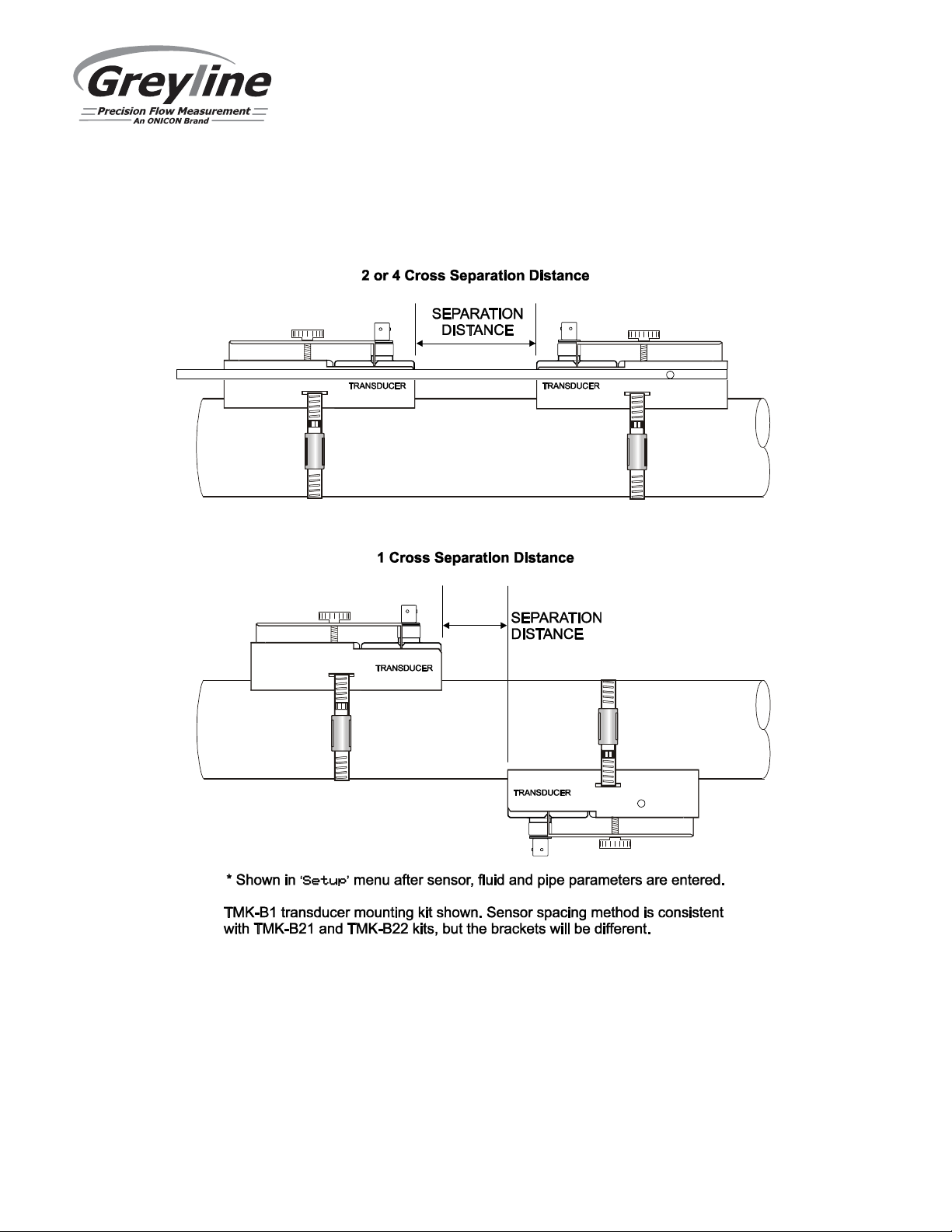
SEPARATION DISTANCE (Sensor Spacing Distance)
Separation distance is automatically calculated by the TTFM 6.1 based on parameters entered in the
Setup menu. Sens Space is parameter where this distance is given, and it is located in the Setup
menu. Document this value for the following transducer installation procedure.
2 OR 4 CROSS INSTALLATION OVERVIEW - TMK-B1 Kit
1. Prep the pipe per instructions on page 28, and mind the installation location requirements on
page 30. Clean the location where the sensor is to be mounted on the opposite side of the pipe
after we’ve marked where it will be installed. Picture below shows a very clean ductile iron pipe
which did not require much cleaning. The outside paint is very well bonded and did not need to
be removed:
2. Install the stainless steel mounting brackets on the pipe. Position them at approximately the
correct separation distance. Exact measurement is not required at this time. Tip: Use a 5/16” nut
driver to tighten the hose clamps.
Procedure continued on the next page…
Page 31
Page 32

TTFM 6.1 Transit Time Flow Meter
2 OR 4 CROSS INSTALLATION OVERVIEW - TMK-B1 Kit (Cont.)
3. Use alignment bar to ensure the brackets are parallel. Completion of steps 2 & 3 is shown below.
4. Mark the position of the permanent bracket on the pipe. This is the bracket that will not be
adjusted, and will be used as the reference for the separation distance and alignment. It is your
choice which bracket is permanent. With a marker, mark the bracket position by placing the
mark directly in front of the stainless side-rail.
Page 32
Page 33

TTFM 6.1 Transit Time Flow Meter
2 OR 4 CROSS INSTALLATION OVERVIEW - TMK-B1 Kit (Cont.)
5. Measure the separation distance from the mark you created in step 4, and create a new mark on
the pipe at the separation distance. It may be useful to mark your Greyline tape measure
(included with every meter) at the separation distance point before marking the pipe. The marked
pipe is shown below.
6. Move the non-permanent bracket to position at the mark you created at step 5, and tighten it
completely. Apply coupling compound to the transducers, and install them in the brackets.
Tips for installing transducers:
a. Be sure the red knob on the brackets are loosened completely
b. Put the transducer into the bracket by ensuring the bottom of the transducer and the
couplant does not touch the pipe as you slide it in. (Hover)
c. With the transducer hovering, tighten the red knob on the bracket until thight. The
transducer will be level with the surface of the pipe, and no grease will have smeared off.
(pictures of proper coupling application and finished installation on the next page)
Page 33
Page 34

TTFM 6.1 Transit Time Flow Meter
2 OR 4 CROSS INSTALLATION OVERVIEW - TMK-B1 Kit (Cont.)
Proper coupling compound application:
Finished installation, ready for cable connection:
7. If you need to make fine adjustments (±0.25”) to the spacing at this point, you may do so by
loosening the hose clamps slightly, and sliding the brackets while the transducers are installed
inside them. Tighten hose clamps when done.
Page 34
Page 35

TTFM 6.1 Transit Time Flow Meter
SEPARATION DISTANCE (Sensor Spacing Distance)
Separation distance is automatically calculated by the TTFM 6.1 based on parameters entered in the
Setup menu. Sens Space is parameter where this distance is given, and it is located in the Setup menu.
Document this value for the following transducer installation procedure.
1 CROSS INSTALLATION OVERVIEW – TMK-B1 Kit
To assist with the proper installation of the transducers in a 1 cross installation, we provide a kit with
every meter, which consists of the following:
Sanding block
Tape measure
Mylar sleeve
Duct tape
Level
Black Sharpie
Follow along with the 1 cross installation instructions on the following pages for a description of where
to use these tools.
1. Prep the pipe per instructions on page 28, and mind the installation location requirements on
page 30. Clean the location where the sensor is to be mounted on the opposite side of the pipe
after we’ve marked where it will be installed. The picture below shows a very clean ductile iron
pipe which did not require much cleaning.
Page 35
Page 36

TTFM 6.1 Transit Time Flow Meter
2. Install one of the stainless steel mounting brackets on the pipe. This will be the stationary bracket
not being rotated to the opposite side of the pipe. For a horizontal pipe, position the bracket at 3
or 9 o’clock. Hold the level up to the top of the bracket to ensure the angle is correct. For vertical
pipes, the bracket can be at any orientation about the pipe. Tip: Use a 5/16” nut driver to tighten
the hose clamp. Install the second bracket at approximately the distance specified by the Sens
Space value in the Setup menu.
3. Use alignment bar to ensure that the brackets are parallel. Completion of steps 2 and 3 is shown
below.
Page 36
Page 37

TTFM 6.1 Transit Time Flow Meter
4. Mark the position of the bracket on the pipe. Mark both where the front of the bracket is, as well
as the center of the bracket.
5. Measure the separation distance from the marks you created in step 4, and create new marks on
the pipe at the separation distance. It may be useful to mark your Greyline tape measure at the
separation distance before holding it up to and marking the pipe.
Page 37
Page 38

TTFM 6.1 Transit Time Flow Meter
6. Using the mylar sleeve included with the installation kit, wrap it around the pipe, keep it taut,
and with the Sharpie, draw a line anywhere the sleeve overlaps:
7. Lay the mylar sleeve flat, use duct tape to help hold it flat if you need to, and use the tape
measure to measure half way between the two marks created when you wrapped the mylar
around the pipe:
Page 38
Page 39

TTFM 6.1 Transit Time Flow Meter
8. Position the marked mylar back on the pipe, with the overlap marks on the center line of the
transducer bracket that will be rotated to the other side of the pipe. Be sure the mylar is parallel
with the face of the transducer. Use duct tape to hold the mylar together and to the pipe. While
the mylar is in this position, mark the opposite side of the pipe where the mylar is marked from
step 7:
Page 39
Page 40

TTFM 6.1 Transit Time Flow Meter
9. Sand the pipe at this position if it needs to be prepped because of scale or rust. After prepped,
move the bracket to this 1 cross mark, and tighten it in place. Apply coupling compound to the
transducers and place them in the brackets:
Tips for installing transducers:
a. Be sure the red knob on the brackets are loosened completely.
b. Put the transducer into the bracket by ensuring the bottom of the transducer and the
couplant does not touch the pipe as you slide it in (hover).
c. With the transducer hovering, tighten the red knob on the bracket until tight. The
transducer will be level with the surface of the pipe, and no grease will have smeared off
from inserting the transducer in the bracket.
Proper coupling compound application:
Page 40
Page 41

Finished installation:
TTFM 6.1 Transit Time Flow Meter
10. If you need to make fine adjustments (±0.25”) to the spacing at this point, you may do so by
loosening the hose clamps slightly, and sliding the brackets while the transducers are installed
inside them. Tighten the hose clamps when done.
Page 41
Page 42

TTFM 6.1 Transit Time Flow Meter
SEPARATION DISTANCE (Sensor Spacing Distance)
Separation distance is automatically calculated by the TTFM 6.1 based on parameters entered in the
Setup menu. Sens Space is parameter where this distance is given, and it is located in the Setup
menu. Document this value for the following transducer installation procedure.
2 OR 4 CROSS INSTALLATION OVERVIEW - TMK-B21 or TMK-B22 Kit
1. Prep the pipe per instructions on page 23, and mind the installation location requirements on
page 25. Clean the location where the sensor is to be mounted on the opposite side of the pipe
after we’ve marked where it will be installed. Picture below shows a very clean ductile iron pipe
which did not require much cleaning. The outside paint is very well bonded and did not need to
be removed:
Page 42
Page 43

TTFM 6.1 Transit Time Flow Meter
2 OR 4 CROSS INSTALLATION OVERVIEW - TMK-B21 or TMK-B22 Kit (Cont.)
2. Install the spacer bar onto the right bracket as shown below:
3. Insert the spacer bar into the left bracket, and position the bracket at the separation distance
referenced earlier. Tighten the spacer bar clamp at this position:
Page 43
Page 44

TTFM 6.1 Transit Time Flow Meter
2 OR 4 CROSS INSTALLATION OVERVIEW - TMK-B21 or TMK-B22 Kit (Cont.)
4. Place the bracket assembly on the pipe, tighten it in place with the two hose clamps:
5. Apply coupling compound to the transducers, and install them in the brackets.
Tips for installing transducers:
a. Be sure the tightening Philips screw on the top of the bracket is loosened completely.
b. Put the transducer into the bracket by ensuring the bottom of the transducer and the
couplant does not touch the pipe as you slide it in. (Hover)
c. Tighten the Phillips screws on the bracket until tight. The transducer will be level with
the surface of the pipe, and no grease will have smeared off.
(pictures of proper coupling application and finished installation on the next page)
Page 44
Page 45

TTFM 6.1 Transit Time Flow Meter
2 OR 4 CROSS INSTALLATION OVERVIEW - TMK-B21 or TMK-B22 Kit (Cont.)
Proper coupling compound application:
Finished installation, ready for cable and conduit connection:
6. If you need to make fine adjustments (±0.25”) to the spacing at this point, you may do so by
loosening the hose clamps slightly, and sliding the brackets while the transducers are installed
inside them. Tighten hose clamps when done.
Page 45
Page 46

TTFM 6.1 Transit Time Flow Meter
SEPARATION DISTANCE (Sensor Spacing Distance)
Separation distance is automatically calculated by the TTFM 6.1 based on parameters entered in the
Setup menu. Sens Space is parameter where this distance is given, and it is located in the Setup menu.
Document this value for the following transducer installation procedure.
1 CROSS INSTALLATION OVERVIEW – TMK-B21 or TMK-B22 Kit
To assist with the proper installation of the transducers in a 1 cross installation, we provide a kit with
every meter, which consists of the following:
Sanding block
Tape measure
Mylar sleeve
Duct tape
Level
Black Sharpie
Follow along with the 1 cross installation instructions on the following pages for a description of where
to use these tools.
1. Prep the pipe per instructions on page 28, and mind the installation location requirements on
page 30. Clean the location where the sensor is to be mounted on the opposite side of the pipe
after we’ve marked where it will be installed. The picture below shows a very clean ductile iron
pipe which did not require much cleaning.
Page 46
Page 47

TTFM 6.1 Transit Time Flow Meter
2. Install the spacer bar onto the right bracket as shown below:
3. Insert the spacer bar into the left bracket, and position the bracket at the separation distance
referenced earlier. Tighten the spacer bar clamp at this position:
Page 47
Page 48

TTFM 6.1 Transit Time Flow Meter
4. Place the bracket assembly on the pipe, tighten it in place with the two hose clamps. For a
horizontal pipe, position the bracket at 3 or 9 o’clock. Hold the level up to the top of the bracket
to ensure the angle is correct. For vertical pipes, the bracket can be at any orientation about the
pipe. Tip: Use a 5/16” nut driver to tighten the hose clamp.
5. Mark the position of the center line of the bracket which is to be moved to the opposite side of
the pipe. It is up to you to determine which bracket is easier to move from the current position:
Page 48
Page 49

TTFM 6.1 Transit Time Flow Meter
6. Using the mylar sleeve included with the installation kit, wrap it around the pipe, keep it taut,
and with the Sharpie, draw a line anywhere the sleeve overlaps:
7. Lay the mylar sleeve flat, and use the tape measure to measure half way between the two marks
created when you wrapped the mylar around the pipe:
Page 49
Page 50

TTFM 6.1 Transit Time Flow Meter
8. Position the marked mylar back on the pipe, with the overlap marks on the center line of the
transducer bracket that will be rotated to the other side of the pipe. Be sure the mylar is parallel
with the face of the transducer. Use duct tape to hold the mylar together and to the pipe. While
the mylar is in this position, mark the opposite side of the pipe where the mylar is marked from
step 7:
Page 50
Page 51

TTFM 6.1 Transit Time Flow Meter
9. Sand the pipe at this position if it needs to be prepped because of scale or rust. After prepped,
move the bracket to this 1 cross mark, and tighten it in place. Apply coupling compound to the
transducers and place them in the brackets:
View from front of pipe:
View from back of pipe:
Tips for installing transducers:
a. Be sure the tightening screws on the brackets are loosened completely.
b. Put the transducer into the bracket by ensuring the bottom of the transducer and the
couplant does not touch the pipe as you slide it in (hover).
c. With the transducer hovering, tighten the screws on the bracket until tight. The transducer
will be level with the surface of the pipe, and no grease will have smeared off from
inserting the transducer in the bracket.
Page 51
Page 52

Proper coupling compound application:
TTFM 6.1 Transit Time Flow Meter
Finished installation:
10. If you need to make fine adjustments (±0.25”) to the spacing at this point, you may do so by
loosening the hose clamps slightly, and sliding the brackets while the transducers are installed
inside them. Tighten the hose clamps when done.
Page 52
Page 53
TTFM 6.1 Transit Time Flow Meter
SENSOR MOUNTING/COUPLING RECOMMENDATIONS
Page 53
Page 54
TTFM 6.1 Transit Time Flow Meter
ENCLOSURE INSTALLATION
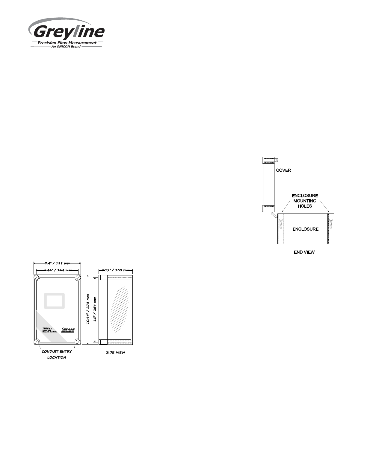
Locate the enclosure within 25 ft (7.6 m) of the sensors (up to 100 ft - 30 m optional). The enclosure can
be wall mounted with the four mounting screws (included) or panel mounted with Option PM Panel
Mount kit from Greyline Instruments.
Avoid mounting the enclosure in direct sunlight to protect the electronics from damage due to
overheating and condensate. In high humidity atmospheres, or where temperatures fall below freezing,
Option TH Enclosure Heater and Thermostat is recommended. IMPORTANT: Seal conduit entries to
prevent moisture from entering enclosure.
NEMA4X (IP66) WITH CLEAR COVER
1. Open hinged enclosure cover.
2. Insert #12 screws (supplied) through the four enclosure mounting holes to
secure the enclosure to the wall or mounting stand.
Additional conduit holes can be cut in the bottom of the enclosure when
required. Use a hole saw or Greenlee-type hole cutter to cut the required
holes.
IMPORTANT: DO NOT make conduit/wiring entries into the top or sides
of the enclosure.
Note: This non-metallic enclosure does not automatically provide grounding between conduit
connections. Grounding must be provided as part of the installation. Ground in accordance with the
requirements of the National Electrical Code. System grounding is provided by connecting grounding
wires from all conduit entries to the steel mounting plate or another point which provides continuity.
CLEANING
Cleaning is not required as a part of normal maintenance.
Page 54
Page 55
FIELD TROUBLESHOOTING
METER READING WHEN THERE IS NO FLOW
?
C
ontact Greyline for further assistan
ce.
VSD
METER READING LOWER THAN EXPECTED
?
selection/fluid velocity.
instrument.
matches Setup menu values.
sensor spacing.
TTFM 6.1 Transit Time Flow Meter
Possible Causes:
Erratic measurement (set damping to
0% to check) due to electrical noise
or poor signal quality.
Variable Speed Drive interference
Calibration Error
Corrective Action:
Set Calibration/ Damping to 0% with zero flow use
Setup / Tare function.
Ensure all Flowmeter wiring is in METAL conduit and sensor
shield is properly connected to Ground.
Ensure correct power input Ground connection (<1 ohm
resistance).
Ensure 4-20mA Shield connected to Instrument Ground stud.
Adjust Calibration / Min Flow setting.
Follow Drive manufacturers wiring and Grounding instructions
Relocate Flowmeter electronics, Sensor and wiring away from
Review calibration menu. Pipe dimensions and fluid
Lower flow rate than expected
Erratic measurement (set damping to
0% to check) due to electrical noise
or poor signal quality.
NO ECHO INDICATION Icon: No Echo
Improper Installation
Sensors not mounted to Pipe or
mounted improperly
Investigate pump/valves. Compare velocity with alternate
Ensure all Flowmeter wiring is in METAL conduit and sensor
shield is properly grounded.
Ensure correct power input Ground connection (<1 ohm
resistance).
Ensure 4-20mA Shield connected to Instrument Ground stud.
Contact Greyline for further assistance.
Check Setup menu to ensure pipe material, size, thickness, liner
type, thickness, fluid type, and fluid temperature and configured
properly. Check transducer mounting method and spacing
Apply coupling compound and mount sensors to pipe with proper
Page 55
Page 56
TTFM 6.1 Transit Time Flow Meter
obtain echoes.
Use
Super Lube
®
Silicone Compound
SENSOR CONNECTIONS
Connections steps
connections.
selection/fluid velocity.
instrument.
C
ontact Greyline for further assistance.
adjustment to Cal Const.
Possible Causes:
NO ECHO INDICATION Icon: No Echo (cont.)
Empty pipe or partially filled
Coupling compound washed out, or
sensor loose on pipe.
OPEN/SHORT SENSOR ICON
Sensor Connections
METER READING HIGHER THAN EXPECTED?
Corrective Action:
Pipe must be fluid filled and acoustically transparent in order to
Remount sensor
No sensors attached
Short in transducer, or in triax transducer cable. Follow Sensor
Check sensor connections at TTFM and at sensor junction box.
Note: Refer to Sensor Cable Resistance Test to test final
Calibration Error
Higher flow rate than expected
Erratic measurement (set damping to
0% to check) due to electrical noise
or poor signal quality.
High viscosity fluid
Review calibration menu. Pipe dimensions and fluid
Investigate pump/valves. Compare velocity with alternate
Ensure all Flowmeter wiring is in METAL conduit and sensor
shield is properly grounded.
Ensure correct power input Ground connection (<1 ohm
resistance).
Ensure 4-20mA Shield connected to Instrument Ground stud.
Laminar flow profile due to high viscosity fluid requires an
Page 56
Page 57

TTFM 6.1 Transit Time Flow Meter
SENSOR CABLE & TRANSDUCER RESISTANCE TEST
Unplug the green sensor terminal from the Transit Time board with the sensor wires still connected and
the BNC end of the cable is connected to the transducer. With a multimeter, perform resistance checks
for each set of wires. One single loose terminal may cause false readings.
Test across shield and core of each wire: TDR1 and TDR2. Resistance should be around 10K ohms for
any cable length. High readings indicate an open circuit and low readings indicate a short or partial short
in the sensor cable connections or transducer.
Note: The TTFM 6.1 will automatically detect connectivity to the sensors. Confirm that TTFM 6.1
indicates “Sensor Good” in the messages menu if your resistance measured is
approximately 10K Ohms.
Page 57
Page 58

TTFM 6.1 Transit Time Flow Meter
COMMON QUESTIONS AND ANSWERS
The pipe vibrates. Will it affect the flow meter?
Common vibration frequencies are far lower than the sonic frequencies used by the Greyline flow meter,
and will not normally affect accuracy or performance. However, applications where very weak Transit
Time signal is present (when sensitivity is adjusted to maximum and signal strength is low), accuracy
may be affected by pipe vibration, or the flow meter may show readings under no-flow conditions.
Attempt to relocate the sensor on a pipe section where vibration is reduced, or arrange pipe mounting
brackets to reduce vibration at the sensor mounting location.
The flow meter must be installed in a high noise environment. Will this affect operation?
Greyline flow meters are designed to discriminate between environmental noise and the Transit Time
signal. High noise environments may affect the flow meter’s performance where low signal strength
and/or low flow velocities are being measured. Relocate the sensor in a quieter environment if possible.
Will pipe corrosion affect accuracy of the flow meter?
Yes. Rust, loose paint etc. must be removed from the outside of the pipe to provide a clean mounting
position when installing a Transit Time sensor. Severe corrosion/oxidation on the inside of the pipe may
prevent the Transit Time signal from penetrating into the flow. If the pipe cannot be cleaned, a spool
piece (PVC recommended) should be installed for sensor mounting.
What effect do pipe liners have on the flow meter?
The air gap between loose insertion liners and the pipe wall prevent the Transit Time signal from
entering the flow. Better results can be expected with bonded liners such as cement, epoxy or tar,
however an on site test is recommended to determine if the application is suitable for a Transit Time
flow meter.
Why is Transit Time recommended for clean liquids?
The Transit Time sensor transmits sound across the flow stream in order to measure the time it takes to
arrive at the other sensor, and therefore requires a fluid medium that is relatively transparent to the
acoustic signal. The Transit Time system will not function when there is high volume of solids or
aeration. As a guideline, Greyline Transit Time flow meters are recommended for clean liquids with
solids or bubbles content less than 2% by volume.
Can the sensor be submerged in water?
Yes, for short periods of time or by accident, but it is not recommended for continuous operation. The
sensor is constructed to withstand submersion to 10 psi (0.7 Bar) without damage provided the
protective rubber boot is filled with Super Lube®.
Page 58
Page 59

TTFM 6.1 Transit Time Flow Meter
What is the purpose of the Signal Strength Display?
The primary function of the signal strength display is to assist as a feedback when mounting sensors.
Signal Strength can also be a useful diagnostics tool when troubleshooting problems with an installation.
A signal strength less than 100% may indicate a problem with the installation or other issues such as a
mis-programmed pipe size, pipe material, fluid type or temperature, or wrong transducer spacing. A
signal strength less than 100% may also simply indicate a lot of aeration, or deteriorated pipe.
Consideration should be made to use a 1 cross installation in such a case.
Can I change the length of the sensor cable?
Yes. The Greyline Transit Time design allow cable lengths up to 100 ft (30 m) or extension up to 250 ft
with extra cable and JB2X optional junction box. Replacement cable of different length may be installed
in rigid or flexible conduit for mechanical protection. Use only Greyline shielded triaxial cable.
Does the TTFM 6.1 require periodic recalibration?
TTFM 6.1 calibration does not drift over time. The solid state sensor has no moving parts to wear and
affect calibration. All Greyline timing/counting circuits use crystal-controlled frequency references to
eliminate any drift in the processing circuitry.
ISO 9000 or similar quality management systems may require periodic and verifiable recalibration of
flow meters. TTFM 6.1 Flow Meters may be returned to Greyline for factory calibration and issue of a
new NIST traceable certificate. Refer to the ‘Product Return Procedure’ section of this manual for return
instructions.
Page 59
Page 60

TTFM 6.1 Transit Time Flow Meter
APPLICATIONS HOTLINE
For applications assistance, advice or information on any Greyline Instrument contact your Sales
Representative, write to Greyline or phone the Applications Hotline below:
United States: Tel: 315-788-9500 Fax: 315-764-0419
Canada: Tel: 613-938-8956 Fax: 613-938-4857
Toll Free: 888-473-9546
Email: [email protected]
Web Site: www.greyline.com
Greyline Instruments Inc.
USA Canada
11451 Belcher Road South 16456 Sixsmith Drive
Largo, FL 33773 Long Sault, Ont. K0C 1P0
PRODUCT RETURN PROCEDURE
Instruments may be returned to Greyline for service or warranty repair.
1 Obtain an RMA Number from Greyline -
Before shipping a product to the factory please contact Greyline by telephone, fax or email to obtain an
RMA number (Returned Merchandise Authorization). This ensures fast service and correct billing or
credit.
When you contact Greyline please have the following information available:
1. Model number / Software Version
2. Serial number
3. Date of Purchase
4. Reason for return (description of fault or modification required)
5. Your name, company name, address and phone number
2 Clean the Sensor/Product -
Important: unclean products will not be serviced and will be returned to the sender at their expense.
1. Rinse sensor and cable to remove debris.
2. If the sensor has been exposed to sewage, immerse both sensor and cable in a solution of 1 part
household bleach (Javex, Clorox etc.) to 20 parts water for 5 minutes. Important: do not immerse
open end of sensor cable.
3. Dry with paper towels and pack sensor and cable in a sealed plastic bag.
4. Wipe the outside of the enclosure to remove dirt or deposits.
5. Return to Greyline for service.
Page 60
Page 61
TTFM 6.1 Transit Time Flow Meter
LIMITED WARRANTY
_____________________________________
Greyline Instruments warrants, to the original purchaser, its
products to be free from defects in material and workmanship for a
period of one year from date of invoice. Greyline will replace or
repair, free of charge, any Greyline product if it has been proven to
be defective within the warranty period. This warranty does not
cover any expenses incurred in the removal and re-installation of
the product.
If a product manufactured by Greyline should prove defective
within the first year, return it freight prepaid to Greyline
Instruments along with a copy of your invoice.
This warranty does not cover damages due to improper installation
or handling, acts of nature, or unauthorized service. Modifications
to or tampering with any part shall void this warranty. This
warranty does not cover any equipment used in connection with the
product or consequential damages due to a defect in the product.
All implied warranties are limited to the duration of this warranty.
This is the complete warranty by Greyline and no other warranty is
valid against Greyline. Some states do not allow limitations on how
long an implied warranty lasts or limitation of incidental or
consequential damages, so the above limitations or exclusions may
not apply to you.
This warranty gives you specific legal rights, and you may also
have other rights which vary from state to state.
Greyline Instruments Inc.
Page 61
Page 62
TTFM 6.1 Transit Time Flow Meter
ENCLOSURE HEATER AND THERMOSTAT - Option TH
Instruments can be factory-equipped with an Enclosure Heater and Thermostat or the module can be
customer-installed. The Thermostat is factory set to turn ON at 40°F (4.5°C) and OFF at 60°F (15.5°C).
Power consumption is 15 Watts.
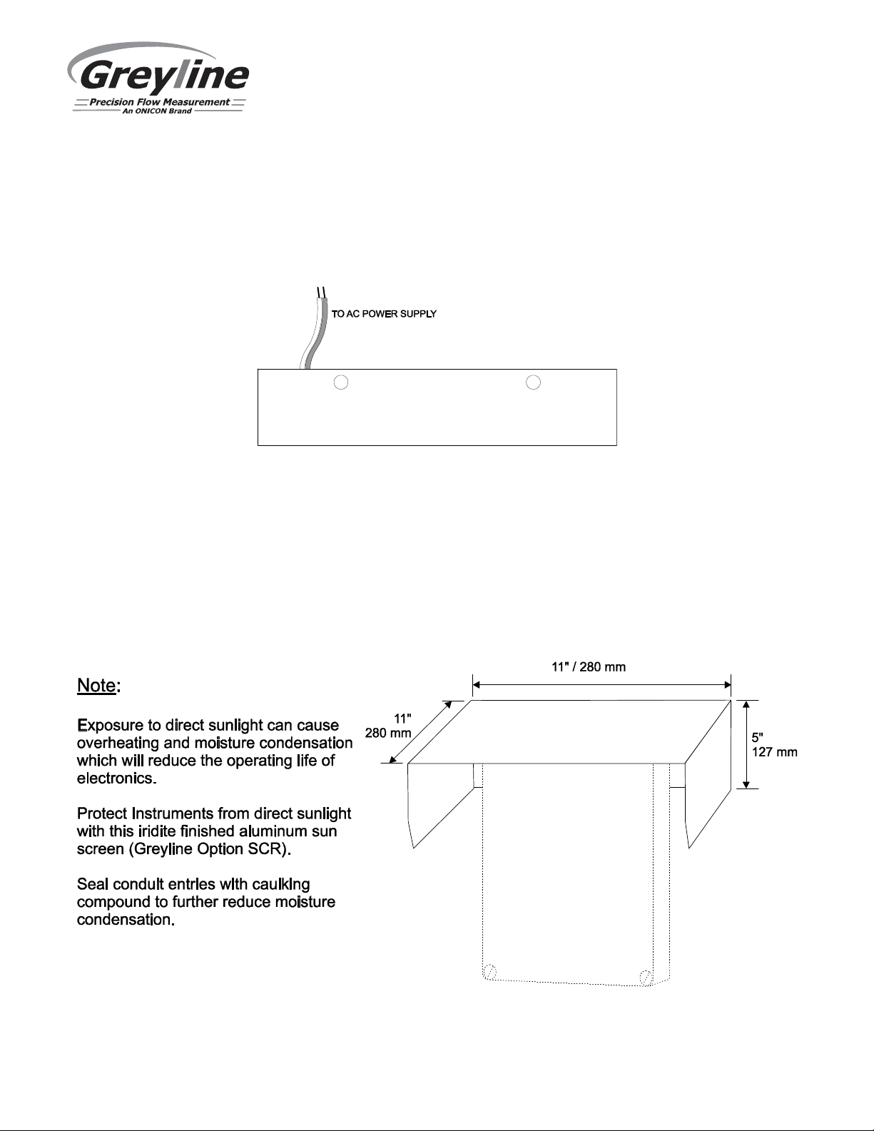
ENCLOSURE SUNSCREEN - Option SCR
Do not mount instrument electronics in direct sunlight. Overheating will reduce the life of electronic
components and condensate may form during the heat/cool cycles and cause electrical shorts.
Page 62
Page 63
TTFM 6.1 Transit Time Flow Meter
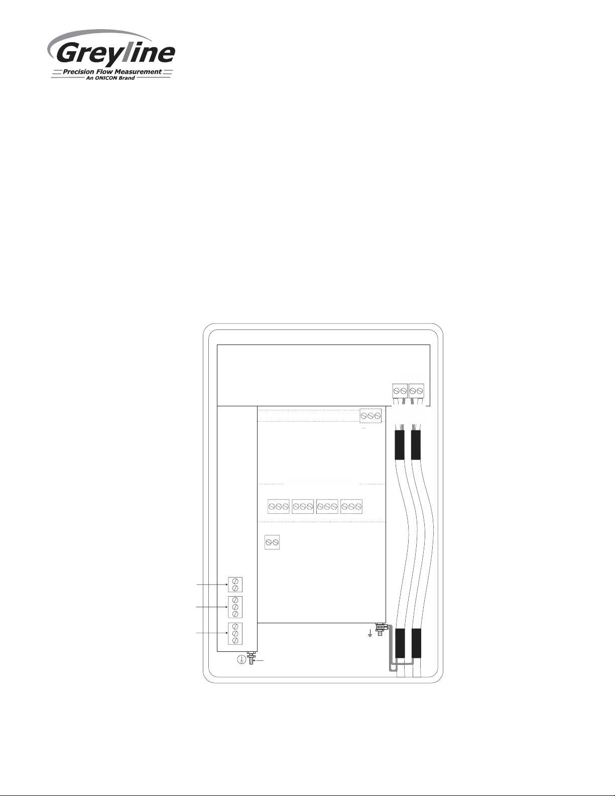
POWER INPUT OPTION
9-32VDC
TTFM 6.1 Flow Meters may be ordered factory-configured for 9-32VDC power input, or a 9-32VDC
Power Input card can be installed in the place of the 100-240VAC card in the field.
CONNECTIONS:
POWER INPUT: Connect 9-32VDC to the + and - terminals. The Power Input GND terminal must be
connected to the nearest Ground pole. A 1 amp fuse in line is recommended.
4-20mA
RLY2
RLY1
SERIAL COMMUNICATION OPTION
EXTRA RELAYS OPTION
NCCNONCCNONCCNONCC
RLY3 RLY4 RLY5 RLY6
9-32 VDC
POWER
INPUT
+ -
–
+
NO
C
NC
NO
C
NC
DC
GND
SENSOR
GND
+ G
RS-485
Output
NO
SENSOR
GND
GND
TDR 1
TDR 2
Upstream
Downstream
Page 63
Page 64
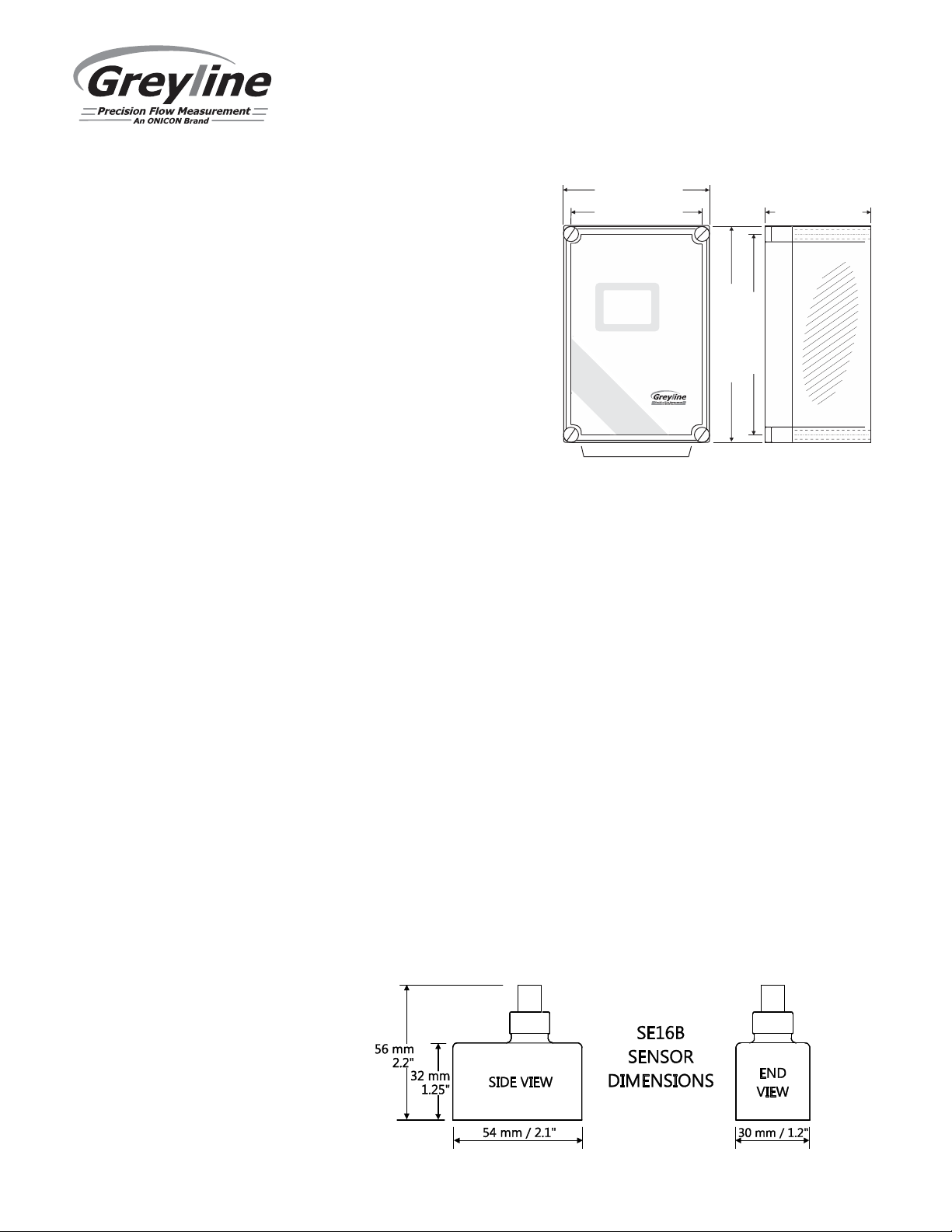
SPECIFICATIONS
7.4
/ 1 88 mm
"
LOCATION
TTFM 6.1 Transit Time Flow Meter
Flow Rate Range: ±0.07 to 40 ft/sec (±0.02
6.46 / 16 4 mm"
to 12 m/sec)
Pipe Size: 2” to 48” (50 to 1200 mm)
Accuracy: ±1% of flow rate from 1.5
to 40 ft/sec, ±0.015 ft/sec
below 1.5 ft/sec.
Repeatability and
Linearity: ±0.25%
Displays: White, backlit matrix -
displays flow rate,
totalizer, relay states,
TTFM .61
Transit Time
Ultrasonic Flow Meter
10.94" / 2 78 mm
operating mode and
calibration menu
Calibration: built-in 5-key calibrator
with English, French or
CONDUIT ENT RY
Spanish language
selection
Power Input: 100-240VAC, 50/60Hz, 10VA or
Optional 9-32VDC, 10 Watts Maximum
Output: Isolated 4-20mA (1000 ohm load max.). Can be changed to 0-5VDC in
programming
Data Logger: 128MB Data Storage
Control Relays: Qty 2, rated 5 amp 240VAC SPDT, programmable flow alarm and/or
proportional pulse
Enclosure: Watertight, dust tight NEMA4X (IP 66) polycarbonate with a clear
shatter-proof face
Environmental Conditions: Relative humidity up to 80%, -23 to 60°C ambient temperature,
maximum 5000 m altitude, pollution degree 4, Installation Category II.
Electrical Surge Protection: Sensor, 4-20mA output and AC power input
Approximate Shipping Weight: 12 lbs (5.5 kg)
5.12 / 13 0 mm"
10 / 2 54 mm"
SIDE VIEW
SE16 Transit Time Sensor
Pipe Diameter: 2” to 48” (50 to 1200 mm)
Operating Temperature: -40° to 300°F (-40° to 150°C)
Exposed Materials: 31655
Operating Frequency: 1.28 MHz
Sensor Cable: 25 ft (7.6 m)
Optional 50 ft (15 m) or 100 ft (30 m) available, extendable up to 500 ft
(150 m) with JB2X optional junction box.
Submersion Rating: Withstands accidental submersion pressure up to 10 psi (0.7 Bar)
Page 64
Page 65
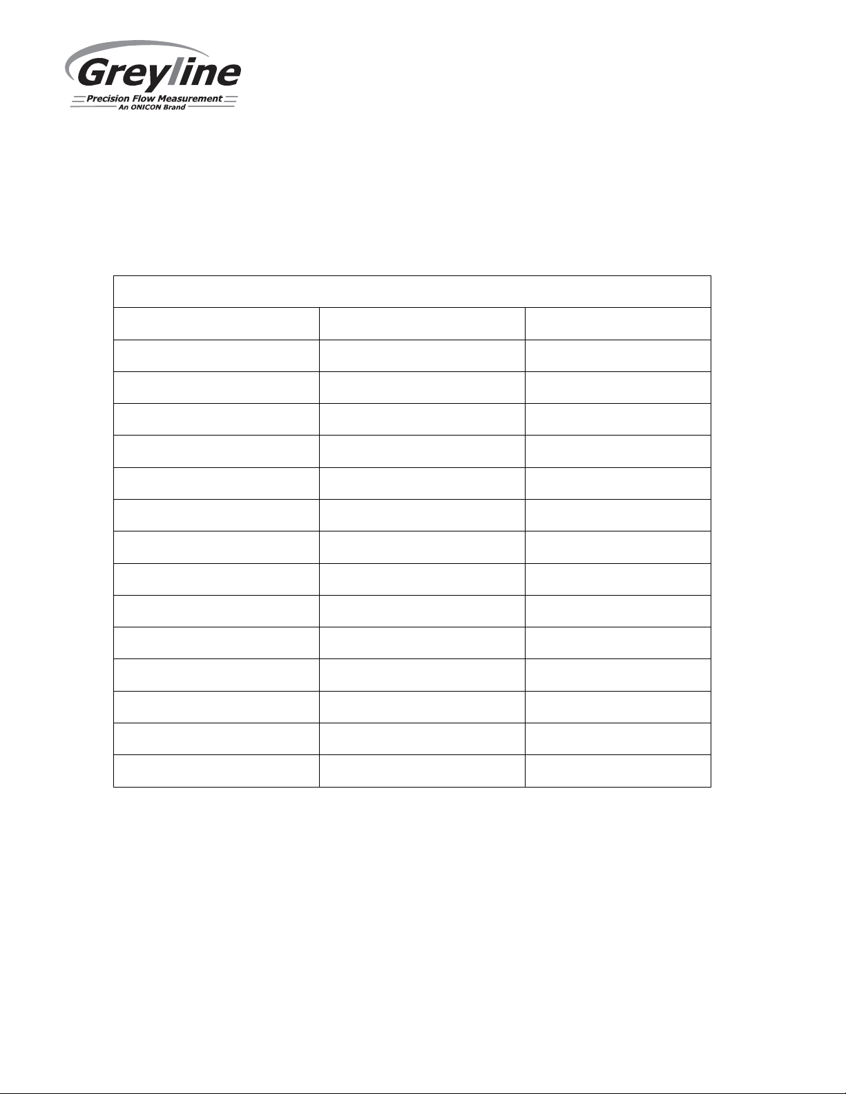
TTFM 6.1 Transit Time Flow Meter
APPENDIX A - CONVERSION TABLE
CONVERSION GUIDE
FROM TO MULTIPLY BY
US GALLONS CUBIC FEET 0.1337
US GALLONS IMPERIAL GALS 0.8327
US GALLONS LITRES 3.785
US GALLONS CUBIC METERS 0.003785
LITRES/SEC GPM 15.85
LITRES CUBIC METERS 0.001
BARRELS (bbl) US GALLONS 42
BARRELS (bbl) IMPERIAL GALS 34.9726
BARRELS (bbl) LITRES 158.9886
INCHES MM 25.4
DEGREES F DEGREES C (°F-32) x 0.556
POUNDS KILOGRAMS 0.453
PSI BAR 0.0676
FOOT² METER² 0.0929
Note: BARRELS (bbl) are U.S. oil barrels.
Page 65
Page 66
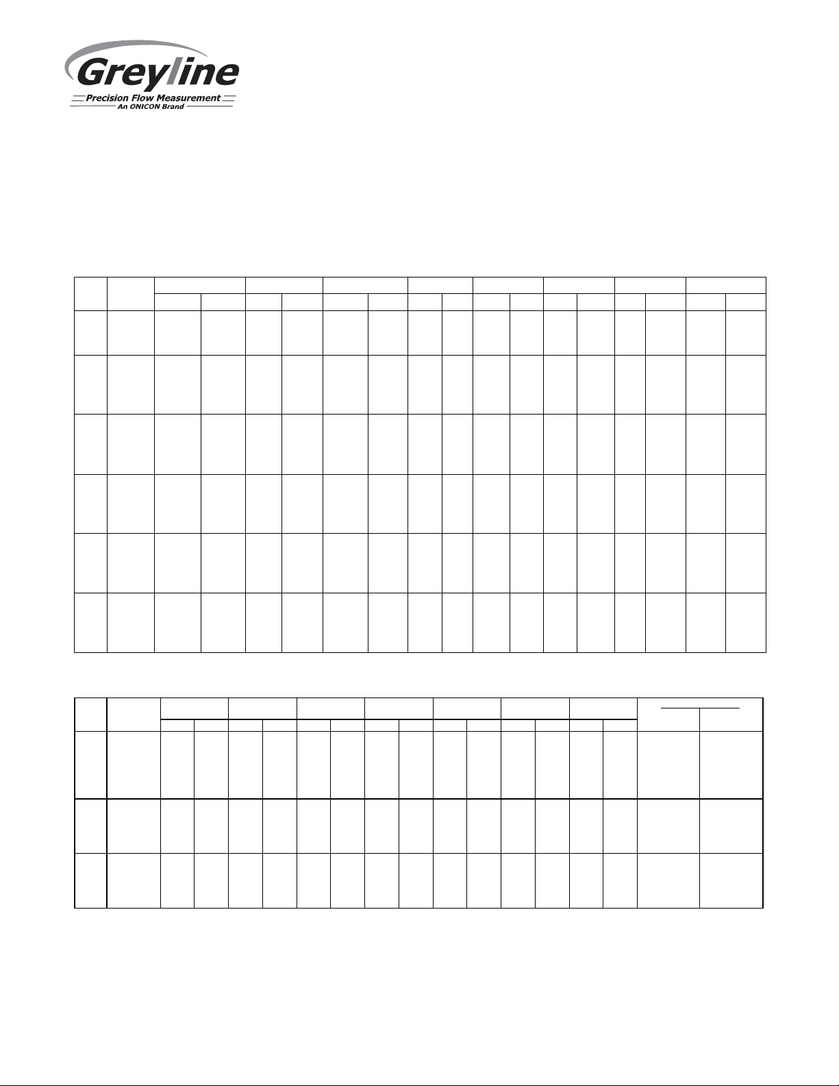
TTFM 6.1 Transit Time Flow Meter
PIPE CHARTS
Note: Not all pipe types allowed in programming have charts below. Pipe dimensions will need
to be acquired from pipe markings or the pipe manufacturer in such cases.
Carbon Steel & PVC Pipe
Pipe Pipe ScheduleStandard Extra Heavy Dbl. ExtraHeavy Schedule10 Schedule20 Schedule 30 Schedule40 Schedule80
Size O.D. I.D. WALL I.D. WALL I.D. WALL I.D. WALL I.D. WALL I.D. WALL I.D. WALL I.D. WALL
2 2.375 2.067 .154 1.939 .218 1.503 .436 2.067 .154 1.939 0.218
2½ 2.875 2.469 .203 2.323 .276 1.771 .552 2.469 .203 2.323 0.276
3 3.500 3.068 .216 2.900 .300 2.300 .600 3.068 .216 2.900 0.300
3½ 4.000 3.548 .226 3.364 .318 2.728 .636 3.548 .226 3.364 0.318
4 4.500 4.026 .237 3.826 .337 3.152 .674 4.026 .237 3.826 0.337
5 5.563 5.047 .258 4.813 .375 4.063 .750 5.047 .258 4.813 0.375
6 6.625 6.065 .280 5.761 .432 4.897 .864 6.065 .280 5.761 0.432
8 8.625 7.981 .322 7.625 .500 6.875 .875 8.125 .250 8.071 .277 7.981 .322 7.625 0.500
10 10.750 10.020 .365 9.750 .500 8.750 1.000 10.250 .250 10.136 .307 10.020 .365 9.564 0.593
12 12.750 12.000 .375 11.750 .500 10.750 1.000 12.250 .250 12.090 .330 11.938 .406 11.376 0.687
14 14.000 13.250 .375 13.000 .500 13.500 .250 13.376 .312 13.250 .375 13.124 .438 12.500 0.750
16 16.000 15.250 .375 15.000 .500 15.500 .250 15.376 .312 15.250 .375 15.000 .500 14.314 0.843
18 18.000 17.250 .375 17.000 .500 17.500 .250 17.376 .312 17.124 .438 16.876 .562 16.126 0.937
20 20.000 19.250 .375 19.000 .500 19.500 .250 19.250 .375 19.000 .500 18.814 .593 17.938 1.031
22 22.000 21.250 .375 21.000 .500 21.500 .250 21.250 .375 21.000 .500
24 24.000 23.250 .375 23.000 .500 23.500 .250 23.250 .375 22.876 .562 22.626 .687 21.564 1.218
26 26.000 25.250 .375 25.000 .500 25.376 .312 25.000 .500
28 28.000 27.250 .375 27.000 .500 27.376 .312 27.000 .500 26.750 .625
30 30.000 29.250 .375 29.000 .500 29.376 .312 29.000 .500 28.750 .625
32 32.000 31.250 .375 31.000 .500 31.376 .312 31.000 .500 30.750 .625
34 34.000 33.250 .375 33.000 .500 33.376 .312 33.000 .500 32.750 .625
36 36.000 35.250 .375 35.000 .500 35.376 .312 35.000 .500 34.750 .625
42 42.000 41.250 .375 41.000 .500 41.000 .500 40.750 .625
Ductile Iron Pipe – Standard Classes
Size OUT SIDE C l ass Cla ss Cl as s Cla ss Cl ass Class Class CE ME NT LINING
INCH DIA. 50 51 5 2 53 5 4 55 56 **S TD **DOUB LE
**REDUC E I.D. BY DIMENS ION SHO WN
INCH W ALL I.D. WA LL I.D. W ALL I .D. WAL L I.D. WALL I.D . WALL I.D. WA LL I.D . THICKN ESS THICKN ESS
3 3. 96 0.25 3.46 0.28 3 .40 0.31 3 .34 0.34 3 .28 0.37 3.2 2 0.41 3.14
4 4. 80 0.26 4.28 0.29 4 .22 0.32 4 .16 0.35 4 .10 0.38 4.0 4 0.44 3.93
6 6. 90 0. 25 6.40 0.28 6.34 0.31 6 .28 0.34 6 .22 0.37 6 .16 0.40 6.1 0 0.43 6.04 .125 .250
8 9. 05 0. 27 8.51 0.30 8.45 0.33 8 .39 0.36 8 .33 0.39 8 .27 0.42 8.2 1 0.45 8.15
10 11.10 0.39 10.32 0.3 2 10 .46 0.35 1 0.40 0.38 10.3 4 0.41 10.28 0.44 10.22 0 .47 1 0.16
12 13.20 0.31 12.58 0.3 4 12 .52 0.37 1 2.46 0.40 12.4 0 0.43 12.34 0.46 12.28 0 .49 1 2.22
14 15.30 0.33 14.64 0.3 6 14 .58 0.39 1 4.52 0.42 14.4 6 0.45 14.40 0.48 14.34 0 .51 1 4.28
16 17.40 0.34 16.72 0.3 7 16 .66 0.40 1 6.60 0.43 16.5 4 0.46 16.48 0.49 16.42 0 .52 1 6.36
18 19.50 0.35 18.80 0.3 8 18 .74 0.41 1 8.68 0.44 18.6 2 0.47 18.56 0.50 18.50 0 .53 1 8.44 .18 75 .375
20 21.60 0.36 20.88 0.3 9 20 .82 0.42 2 0.76 0.45 20.7 0 0.48 20.64 0.51 20.58 0 .54 2 0.52
24 25.80 0.38 25.04 0.4 1 24 .98 0.44 2 4.92 0.47 24.8 6 0.50 24.80 0.53 24.74 0 .56 2 4.68
30 32.00 0.39 31.22 0.4 3 31 .14 0.47 3 1.06 0.51 30.9 8 0.55 30.90 0.59 30.82 0 .63 3 0.74
36 38.30 0.43 37.44 0.4 8 37 .34 0.62 3 7.06 0.58 37.1 4 0.63 37.04 0.68 36.94 0 .73 3 6.84
42 44.50 0.47 43.56 0.5 3 43 .44 0.59 4 3.32 0.65 43.2 0 0.71 43.08 0.77 42.96 0 .83 4 2.84 .250 .500
48 50.80 0.51 49.78 0.5 8 49 .64 0.65 4 9.50 0.72 49.3 6 0.79 49.22 0.86 49.08 0 .93 4 8.94
54 57.10 0.57 55.96 0.6 5 55 .80 0.73 5 5.64 0.81 55.4 8 0.89 55.32 0.97 55.16 1 .05 5 5.00
Page 66
Page 67
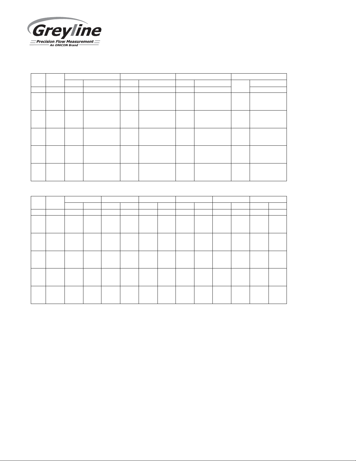
TTFM 6.1 Transit Time Flow Meter
Stainless Steel, Hastelloy "C" & Titanium Pipe
Pipe
Pipe
Scheule 5 S (a)
Schedule 10 S (a)
Schedule 40 S
Schedule 80 S
Size
O.D.
I.D.
WALL
I.D.
WALL
I.D.
WALL
I.D.
WALL
2
2.375
2.245
.065
2.157
.109
2.067
.154
1.939
.218
2½
2.875
2.709
.083
2.635
.120
2.469
.203
2.323
.276
3
3.500
3.334
.083
3.260
.120
3.068
.216
2.900
.300
3½
4.000
3.834
.083
3.760
.120
3.548
.226
3.364
.318
4
4.500
4.334
.083
4.260
.120
4.026
.237
3.826
.337
5
5.563
5.345
.109
5.295
.134
5.047
.258
4.813
.37566.625
6.407
.109
6.357
.134
6.065
.280
5.761
.432
8
8.625
8.407
.109
8.329
.148
7.981
.322
7.625
.5001010.750
10.482
.134
10.420
.165
10.020
.365
9.750
.5001212.750
12.438
.156
12.390
.180
12.000
.375
11.750
.500
14
14.000
13.688
.156
13.624
.188
16
16.000
15.670
.165
15.624
.188
18
18.000
17.670
.165
17.624
.188
20
20.000
19.634
.188
19.564
.218
22
22.000
21.624
.188
21.564
.218
24
24.000
23.563
.218
23.500
.250
Pipe
Pipe
Schedule 60
Schedule 80
Schedule 100
Schedule 120
Schedule 140
Schedule 160
Size
O.D.
I.D.
WALL
I.D.
WALL
I.D.
WALL
I.D.
WALL
I.D.
WALL
I.D.
WALL
2½
2.875
2.323
.276
2.125
.375
3½
4.000
3.364
.318
5
5.563
4.813
.375
4.563
.500
4.313
.625
6
6.625
5.761
.432
5.501
.562
5.189
.718
8
8.625
7.813
.406
7.625
.500
7.439
.593
7.189
.718
7.001
.812
6.813
.9061010.750
9.750
.500
9.564
.593
9.314
.718
9.064
.843
8.750
1.000
8.500
1.125
12
12.750
11.626
.562
11.376
.687
11.064
.843
10.750
1.000
10.500
1.125
10.126
1.312
14
14.000
12.814
.593
12.500
.750
12.126
.937
11.814
1.093
11.500
1.250
11.188
1.406
16
16.000
14.688
.656
14.314
.843
13.938
1.031
13.564
1.218
13.124
1.438
12.814
1.593
18
18.000
16.500
.750
16.126
.937
15.688
1.156
15.250
1.375
14.876
1.562
14.438
1.781
20
20.000
18.376
.812
17.938
1.031
17.438
1.281
17.000
1.500
16.500
1.750
16.064
1.968
22
22.000
20.250
.875
19.750
1.125
19.250
1.375
18.750
1.625
18.250
1.875
17.750
2.125
24
24.000
22.064
.968
21.564
1.218
20.938
1.531
20.376
1.812
19.876
2.062
19.314
2.343
2 2.375 1.939 .218 1.689 .343
3 3.500 2.900 .300 2.624 .438
4 4.500 3.826 .337 3.624 .438 3.438 .531
Page 67
Page 68
TTFM 6.1 Transit Time Flow Meter
Cast Iron Pipe
-
ASA Standard
Pipe
Pipe
Class 50
Class 100
Class 150
Class 200
Class 250
Class 300
Class 350
Size
O.D.
WALL
I.D.
WALL
I.D.
WALL
I.D.
WALL
I.D.
WALL
I.D.
WALL
I.D.
WALL
I.D.
3
3.96
0.32
3.32
0.32
3.32
0.32
3.32
0.32
3.32
0.32
3.32
0.32
3.32
0.32
3.3244.80
0.35
4.10
0.35
4.10
0.35
4.10
0.35
4.10
0.35
4.10
0.35
4.10
0.35
4.1066.90
0.38
6.14
0.38
6.14
0.38
6.14
0.38
6.14
0.38
6.14
0.38
6.14
0.38
6.14
8
9.05
0.41
8.23
0.41
8.23
0.41
8.23
0.41
8.23
0.41
8.23
0.41
8.23
0.41
8.23
10
11.10
0.44
10.22
0.44
10.22
0.44
10.22
0.44
10.22
0.44
10.22
0.48
10.14
0.52
10.06
12
13.20
0.48
12.24
0.48
12.24
0.48
12.24
0.48
12.24
0.52
12.16
0.52
12.16
0.56
12.081415.30
0.48
14.34
0.51
14.28
0.51
14.28
0.55
14.20
0.59
14.12
0.59
14.12
0.64
14.02
16
17.40
0.54
16.32
0.54
16.32
0.54
16.32
0.58
16.24
0.63
16.14
0.68
16.04
0.68
16.04
18
19.50
0.54
18.42
0.58
18.34
0.58
18.34
0.63
18.24
0.68
18.14
0.73
18.04
0.79
17.92
20
21.60
0.57
20.46
0.62
20.36
0.62
20.36
0.67
20.26
0.72
20.16
0.78
20.04
0.84
19.92
24
25.80
0.63
24.54
0.68
24.44
0.73
24.34
0.79
24.22
0.79
24.22
0.85
24.10
0.92
23.96
Cast Iron Pipe
-
AWWA Standard
Pipe
Class A
Class B
Class C
Class D
100 Ft. 43 PSIG
200 Ft. 86 PSIG
300 Ft. 130 PSIG
400 Ft. 173 PSIG
Size
O.D.
WALL
I.D.
O.D.
WALL
I.D.
O.D.
WALL
I.D.
O.D.
WALL
I.D.
3
3.80
0.39
3.02
3.96
0.42
3.12
3.96
0.45
3.06
3.96
0.48
3.00
4
4.80
0.42
3.96
5.00
0.45
4.10
5.00
0.48
4.04
5.00
0.52
3.96
6
6.90
0.44
6.02
7.10
0.48
6.14
7.10
0.51
6.08
7.10
0.55
6.00
8
9.05
0.46
8.13
9.05
0.51
8.03
9.30
0.56
8.18
9.30
0.60
8.10
10
11.10
0.50
10.10
11.10
0.57
9.96
11.40
0.62
10.16
11.40
0.68
10.041213.20
0.54
12.12
13.20
0.62
11.96
13.50
0.68
12.14
13.50
0.75
12.00
16
17.40
0.60
16.20
17.40
0.70
16.00
17.80
0.80
16.20
17.80
0.89
16.02
20
21.60
0.67
20.26
21.60
0.80
20.00
22.06
0.92
20.22
22.06
1.03
20.002425.80
0.76
24.28
25.80
0.89
24.02
26.32
1.04
24.22
26.32
1.16
24.00
30
31.74
0.88
29.98
32.00
1.03
29.94
32.40
1.20
30.00
32.74
1.37
30.00
36
37.96
0.99
35.98
38.30
1.15
36.00
38.70
1.36
39.98
39.16
1.58
36.00
42
44.20
1.10
42.00
44.50
1.28
41.94
45.10
1.54
42.02
45.58
1.78
42.02
48
50.50
1.26
47.98
50.80
1.42
47.96
51.40
1.71
47.98
51.98
1.96
48.06
54
56.66
1.35
53.96
57.10
1.55
54.00
57.80
1.90
54.00
58.40
2.23
53.94
60
62.80
1.39
60.02
63.40
1.67
60.06
64.20
2.00
60.20
64.82
2.38
60.06
72
75.34
1.62
72.10
76.00
1.95
72.10
76.88
2.39
72.10
84
87.54
1.72
84.10
88.54
2.22
84.10
Pipe
Class E
Class F
Class G
Class H
500 Ft. 217 PSIG
600 Ft. 260 PSIG
700 Ft. 304 PSIG
800 Ft. 347 PSIG
Size
O.D.
WALL
I.D.
O.D.
WALL
I.D.
O.D.
WALL
I.D.
O.D.
WALL
I.D.
6
7.22
0.58
6.06
7.22
0.61
6.00
7.38
0.65
6.08
7.38
0.69
6.00
8
9.42
0.66
8.10
9.42
0.71
8.00
9.60
0.75
8.10
9.60
0.80
8.00
10
11.60
0.74
10.12
11.60
0.80
10.00
11.84
0.86
10.12
11.84
0.92
10.00
12
13.78
0.82
12.14
13.78
0.89
12.00
14.08
0.97
12.14
14.08
1.04
12.00
14
15.98
0.90
14.18
15.98
0.99
14.00
16.32
1.07
14.18
16.32
1.16
14.00
16
18.16
0.98
16.20
18.16
1.08
16.00
18.54
1.18
16.18
18.54
1.27
16.001820.34
1.07
18.20
20.34
1.17
18.00
20.78
1.28
18.22
20.78
1.39
18.00
20
22.54
1.15
20.24
22.54
1.27
20.00
23.02
1.39
20.24
23.02
1.51
20.00
24
26.90
1.31
24.28
26.90
1.45
24.00
27.76
1.75
24.26
27.76
1.88
24.00
30
33.10
1.55
30.00
33.46
1.73
30.00
14 15.30 0.57 14.16 15.30 0.66 13.98 15.65 0.74 14.17 15.65 0.82 14.01
18 19.50 0.64 18.22 19.50 0.75 18.00 19.92 0.87 18.18 19.92 0.96 18.00
36 39.60 1.80 36.00 40.04 2.02 36.00
Page 68
Page 69
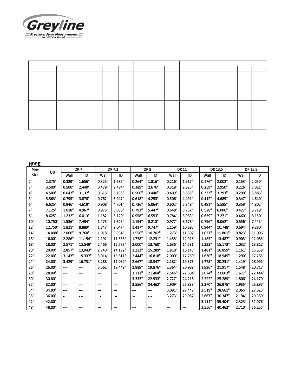
TTFM 6.1 Transit Time Flow Meter
Copper Tubing
Pipe K L M Copper & Brass Pipe Aluminum
Size O.D. I.D. WALL O.D. I.D. WALL O.D. I.D. WALL O.D. I.D. WALL O.D. I.D. WALL
2" 2.125 1.959 0.083 2.125 1.985 0.070 2.125 2.009 0.058 2.375 2.062 0.157
2 ½ 2.625 2.435 0.095 2.625 2.465 0.080 2.625 2.495 0.065 2.875 2.500 0.188 2.500 2.400 0.050
3" 3.125 2.907 0.109 3.125 2.945 0.090 3.125 2.981 0.072 3.500 3.062 0.219 3.000 2.900 0.050
3 ½" 3.625 3.385 0.120 3.625 3.425 0.100 3.625 3.459 0.083 4.000 3.500 0.250
4" 4.125 3.857 0.134 4.125 3.905 0.110 4.125 3.935 0.095 4.500 3.935 0.095 4.000 4.000 0.250
4 ½" 5.000 4.500 0.250
5" 5.125 4.805 0.160 5.125 4.875 0.125 5.125 4.907 0.109 5.563 5.063 0.250 5.000 4.874 0.063
6" 6.125 5.741 0.192 6.125 5.845 0.140 6.125 5.881 0.122 6.625 6.125 0.250 6.000 5.874 0.063
7" 7.625 7.062 0.282 7.000 6.844 0.078
8" 8.125 7.583 0.271 8.125 7.725 0.200 8.125 7.785 0.170 8.625 8.000 0.313 8.000 7.812 0.094
10" 10.125 9.449 0.338 10.125 9.625 0.250 10.125 9.701 0.212 10.000 9.812 0.094
12" 12.125 11.315 0.405 12.125 11.565 0.280 12.125 11.617 0.254
Page 69
Page 70
C900/C905 PVC AWWA Water Distribution Pipe (Blue)
TTFM 6.1 Transit Time Flow Meter
Pipe Size OD
4 4.80 0.343 4.114 0.267 4.266 0.192 4.416
6 6.90 0.493 5.914 0.383 6.134 0.276 6.348
8 9.05 0.646 7.758 0.503 8.044 0.362 8.326
10 11.10 0.793 9.514 0.617 9.866 0.444 10.212
12 13.20 0.943 11.314 0.733 11.734 0.528 12.144
14 15.30 0.850 13.600 0.729 13.842 0.612 14.076
16 17.40 0.967 15.466 0.829 15.742 0.696 16.008
18 19.50 1.083 17.334 0.929 17.642 0.780 17.94
20 21.60 1.200 19.200 1.029 19.542 0.864 19.872
24 25.80 1.433 22.934 1.229 23.342 1.032 23.736
DR14 DR18 DR-21 DR25
Wall ID Wall ID Wall ID Wall ID
Page 70
Page 71
APPENDIX C – Liquid Speed of Sound
Substance Form Index Specific Gravity Sound Speed
m/sec.
Acetic anhydride (22) (CH3CO)2O 1.082 (20ºC) 1180 2.5
Acetic acid, anhydride (22) (CH3CO)2O 1.082 (20ºC) 1180 2.5
Acetic acid, nitrile C2H3N 0.783 1290 4.1
Acetic acid, ethyl ester (33) C4H8O2 0.901 1085 4.4
Acetic acid, methyl ester C3H6O2 0.934 1211
Acetone C3H6O 0.791 1174 4.5
Acetonitrile C2H3N 0.783 1290 4.1
Acetonylacetone C6H10O2 0.729 1399 3.6
Acetylene dichloride C2H2Cl2 1.26 1015 3.8
Acetylene tetrabromide (47) C2H2Br4 2.966 1027
Acetylene tetrachloride (47) C2H2Cl4 1.595 1147
Alcohol C2H6O 0.789 1207 4.0
Alkazene-13 C15H24 0.86 1317 3.9
Alkazene-25 C10H12Cl2 1.20 1307 3.4
2-Amino-ethanol C2H7NO 1.018 1724 3.4
2-Aminotolidine (46) C7H9N 0.999 (20ºC) 1618
4-Aminotolidine (46) C7H9N 0.966 (45ºC) 1480
Ammonia (35) NH3 0.771 1729 6.68
Amorphous Polyolefin 0.98 962.6
t-Amyl alcohol C5H12O 0.81 1204
Aminobenzene (41) C6H5NO2 1.022 1639 4.0
Aniline (41) C6H5NO2 1.022 1639 4.0
Argon (45) Ar 1.400 (-188ºC) 853
Azine C6H5N 0.982 1415 4.1
Benzene (29,40,41) C6H6 0.879 1306 4.65
Benzol(29,40,41) C6H6 0.879 1306 4.65
Bromine (21) Br2 2.928 889 3.0
Bromo-benzene (46) C6H5Br 1.522 1170
1-Bromo-butane (46) C4H9Br 1.276 (20ºC) 1019
Bromo-ethane (46) C2H5Br 1.460 (20ºC) 900
Bromoform (46,47) CHBr3 2.89 (20ºC) 918 3.1
n-Butane (2) C4H10 0.601 (0ºC) 1085 5.8
2-Butanol C4H10O 0.81 1240 3.3
sec-Butylalcohol C4H10O 0.81 1240 3.3
n-Butyl bromide (46) C4H9Br 1.276 (20ºC) 1019
n-Butyl chloride (22,46) C4H9Cl 0.887 1140 4.57
tert Butyl chloride C4H9Cl 0.84 984 4.2
Butyl oleate C22H42O2 1404 3.0
2,3 Butylene glycol C4H10O2 1.019 1484 1.51
Cadmium (7) Cd 2237.7
Carbinol (40,41) CH4O 0.791 (20ºC) 1076 2.92
Carbitol C6H14O3 0.988 1458
Carbon dioxide (26) CO2 1.101 (-37ºC) 839 7.71
Carbon disulphide CS2 1.261 (22ºC) 1149
Carbon tetrachloride(33,35,47) CCl4 1.595 (20ºC) 926 2.48
v/°C - m/s/°C Δ
Page 72
TTFM 6.1 Transit Time Flow Meter
Substance Form Index Specific Gravity Sound Speed
v/°C - m/s/°C Δ
m/sec.
Carbon tetrafluoride (14) CF4 1.75 (-150ºC) 875.2 6.61
Cetane (23) C16H34 0.773 (20ºC) 1338 3.71
Chloro-benezene C6H5Cl 1.106 1273 3.6
1-Chloro-butane (22,46) C4H9Cl 0.887 1140 4.57
Chloro-diFluoromethane (3) (Freon 22) CHClF2 1.491 (-69ºC) 893.9 4.79
Chloroform (47) CHCl3 1.489 979 3.4
1-Chloro-propane (47) C3H7Cl 0.892 1058
Chlorotrifluoromethane (5) CClF3 724 5.26
Cinnamaldehyde C9H8O 1.112 1554 3.2
Cinnamic aldehyde C9H8O 1.112 1554 3.2
Colamine C2H7NO 1.018 1724 3.4
o-Cresol (46) C7H8O 1.047 (20ºC) 1541
m-Cresol (46) C7H8O 1.034 (20ºC) 1500
Cyanomethane C2H3N 0.783 1290 4.1
Cyclohexane (15) C6H12 0.779 (20ºC) 1248 5.41
Cyclohexanol C6H12O 0.962 1454 3.6
Cyclohexanone C6H10O 0.948 1423 4.0
Decane (46) C10H22 0.730 1252
1-Decene (27) C10H20 0.746 1235 4.0
n-Decylene (27) C10 H20 0.746 1235 4.0
Diacetyl C4H6O2 0.99 1236 4.6
Diamylamine C10H23N 1256 3.9
1,2 Dibromo-ethane (47) C2H4Br2 2.18 995
trans-1,2-Dibromoethene(47) C2H2Br2 2.231 935
Dibutyl phthalate C8H22O4 1408
Dichloro-t-butyl alcohol C4H8Cl2O 1304 3.8
2,3 Dichlorodioxane C2H6Cl2O2 1391 3.7
Dichlorodifluoromethane (3) (Freon 12) CCl2F2 1.516 (-40ºC) 774.1 4.24
1,2 Dichloro ethane (47) C2H4Cl2 1.253 1193
cis 1,2-Dichloro-Ethene(3,47) C2H2Cl2 1.284 1061
trans 1,2-Dichloro-ethene(3,47) C2H2Cl2 1.257 1010
Dichloro-fluoromethane (3) (Freon 21) CHCl2F 1.426 (0ºC) 891 3.97
1-2-Dichlorohexafluoro cyclobutane (47) C4Cl2F6 1.654 669
1-3-Dichloro-isobutane C4H8Cl2 1.14 1220 3.4
Dichloro methane (3) CH2Cl2 1.327 1070 3.94
1,1-Dichloro-1,2,2,2 tetra fluoroethane CClF2-CClF2 1.455 665.3 3.73
Diethyl ether C4H10O 0.713 985 4.87
Diethylene glycol, monoethyl ether C6H14O3 0.988 1458
Diethylenimide oxide C4H9NO 1.00 1442 3.8
1,2-bis(DiFluoramino) butane (43) C4H8(NF2)2 1.216 1000
1,2bis(DiFluoramino)- 2-methylpropane
(43)
1,2bis(DiFluoramino) propane (43) C3H6(NF2)2 1.265 960
2,2bis(DiFluoramino) propane (43) C3H6(NF2)2 1.254 890
2,2-Dihydroxydiethyl ether C4H10O3 1.116 1586 2.4
C4H9(NF2)2 1.213 900
Page 72
Page 73
TTFM 6.1 Transit Time Flow Meter
Substance Form Index Specific Gravity Sound Speed
v/°C - m/s/°C Δ
m/sec.
Dihydroxyethane C2H6O2 1.113 1658 2.1
1,3-Dimethyl-benzene (46) C8H10 0.868 (15ºC) 1343
1,2-1.0Dimethyl-benzene(29,46) C8H10 0.897 (20ºC) 1331.5 4.1
1,4-Dimethyl-benzene (46) C8H10 1334
2,2-Dimethyl-butane (29,33) C6H14 0.649 (20ºC) 1079
Dimethyl ketone C3H6O 0.791 1174 4.5
Dimethyl pentane (47) C7H16 0.674 1063
Dimethyl phthalate C8H10O4 1.2 1463
Diiodo-methane CH2I2 3.235 980
Dioxane C4H8O2 1.033 1376
Dodecane (23) C12H26 0.749 1279 3.85
1,2-Ethanediol C2H6O2 1.113 1658 2.1
Ethanenitrile C2H3N 0.783 1290
Ethanoic anhydride (22) (CH3CO)2O 1.082 1180
Ethanol C2H6O 0.789 1207 4.0
Ethanol amide C2H7NO 1.018 1724 3.4
Ethoxyethane C4H10O 0.713 985 4.87
Ethyl acetate (33) C4H8O2 0.901 1085 4.4
Ethyl alcohol C2H6O 0.789 1207 4.0
Ethyl benzene (46) C8H10 0.867(20ºC) 1338
Ethyl bromide (46) C2H5Br 1.461 (20ºC) 900
Ethyliodide (46) C2H5I 1.950 (20ºC) 876
Ether C4H10O 0.713 985 4.87
Ethyl ether C4H10O 0.713 985 4.87
Ethylene bromide (47) C2H4Br2 2.18 995
Ethylene chloride (47) C2H4Cl2 1.253 1193
Ethylene glycol C2H6O2 1.113 1658 2.1
50% Glycol/ 50% H2O 1578
d-Fenochone C10H16O 0.947 1320
d-2-Fenechanone C10H16O 0.947 1320
Fluorine F 0.545 (-143ºC) 403 11.31
Fluoro-benzene (46) C6H5F 1.024 (20ºC) 1189
Formaldehyde, methyl ester C2H4O2 0.974 1127 4.02
Formamide CH3NO 1.134 (20ºC) 1622 2.2
Formic acid, amide CH3NO 1.134 (20ºC) 1622
Freon R12 774
Furfural C5H4O2 1.157 1444
Furfuryl alcohol C5H6O2 1.135 1450 3.4
Fural C5H4O2 1.157 1444 3.7
2-Furaldehyde C5H4O2 1.157 1444 3.7
2-Furancarboxaldehyde C5H4O2 1.157 1444 3.7
2-Furyl-Methanol C5H6O2 1.135 1450 3.4
Gallium Ga 6.095 2870 (@30ºC)
Glycerin C3H8O3 1.26 1904 2.2
Page 73
Page 74
TTFM 6.1 Transit Time Flow Meter
Substance Form Index Specific Gravity Sound Speed
v/°C - m/s/°C Δ
m/sec.
Glycerol C3H8O3 1.26 1904 2.2
Glycol C2H6O2 1.113 1658 2.1
Helium (45) He4 0.125(-268.8ºC) 183
Heptane (22,23) C7H16 0.684 (20ºC) 1131 4.25
n-Heptane (29,33) C7H16 0.684 (20ºC) 1180 4.0
Hexachloro-Cyclopentadiene(47) C5Cl6 1.7180 1150
Hexadecane (23) C16H34 0.773 (20ºC) 1338 3.71
Hexalin C6H12O 0.962 1454 3.6
Hexane (16,22,23) C6H14 0.659 1112 2.71
n-Hexane (29,33) C6H14 0.649 (20ºC) 1079 4.53
2,5-Hexanedione C6H10O2 0.729 1399 3.6
n-Hexanol C6H14O 0.819 1300 3.8
Hexahydrobenzene (15) C6H12 0.779 1248 5.41
Hexahydrophenol C6H12O 0.962 1454 3.6
Hexamethylene (15) C6H12 0.779 1248 5.41
Hydrogen (45) H2 0.071 (-256ºC) 1187
2-Hydroxy-toluene (46) C7H8O 1.047 (20ºC) 1541
3-Hydroxy-tolune (46) C7H8O 1.034 (20ºC) 1500
Iodo-benzene (46) C6H5I 1.823 1114
Iodo-ethane (46) C2H5I 1.950 (20ºC) 876
Iodo-methane CH3I 2.28 (20ºC) 978
Isobutyl acetate (22) C6H12O 1180 4.85
Isobutanol C4H10O 0.81 (20ºC) 1212
Iso-Butane 1219.8
Isopentane (36) C5H12 0.62 (20ºC) 980 4.8
Isopropanol (46) C3H8O 0.785 (20ºC) 1170
Isopropyl alcohol (46) C3H8O 0.785 (20ºC) 1170
Kerosene 0.81 1324 3.6
Ketohexamethylene C6H10O 0.948 1423 4.0
Lithium fluoride (42) LiF 2485 1.29
Mercury (45) Hg 13.594 1449
Mesityloxide C6H16O 0.85 1310
Methane (25,28,38,39) CH4 0.162 405(-89.15ºC) 17.5
Methanol (40,41) CH4O 0.791 (20ºC) 1076 2.92
Methyl acetate C3H6O2 0.934 1211
o-Methylaniline (46) C7H9N 0.999 (20ºC) 1618
4-Methylaniline (46) C7H9N 0.966 (45ºC) 1480
Methyl alcohol (40,44) CH4O 0.791 (20ºC) 1076 2.92
Methyl benzene (16,52) C7H8 0.867 1328 4.27
2-Methyl-butane (36) C5H12 0.62 (20ºC) 980
Methyl carbinol C2H6O 0.789 1207 4.0
Methyl-chloroform (47) C2H3Cl3 1.33 985
Methyl-cyanide C2H3N 0.783 1290
3-Methyl cyclohexanol C7H14O 0.92 1400
Page 74
Page 75
TTFM 6.1 Transit Time Flow Meter
Substance Form Index Specific Gravity Sound Speed
v/°C - m/s/°C Δ
m/sec.
Methylene chloride (3) CH2Cl2 1.327 1070 3.94
Methylene iodide CH2I2 3.235 980
Methyl formate (22) C2H4O2 0.974 (20ºC) 1127 4.02
Methyl iodide CH3I 2.28 (20ºC) 978
2-Methylphenol (46) C7H8O 1.047 (20ºC) 1541
3-Methylphenol (46) C7H8O 1.034 (20ºC) 1500
Milk, homogenized 1548
Morpholine C4H9NO 1.00 1442 3.8
Naphtha 0.76 1225
Natural Gas (37) 0.316 (-103ºC) 753
Neon (45) Ne 1.207 (-246ºC) 595
Nitrobenzene (46) C6H5NO2 1.204 (20ºC) 1415
Nitrogen (45) N2 0.808 (-199ºC) 962
Nitromethane (43) CH3NO2 1.135 1300 4.0
Nonane (23) C9H2O 0.718 (20ºC) 1207 4.04
1-Nonene (27) C9H18 0.736 (20ºC) 1207 4.0
Octane (23) C8H18 0.703 1172 4.14
n-Octane (29) C8H18 0.704 (20ºC) 1212.5 3.50
1-Octene (27) C8H16 0.723 (20ºC) 1175.5 4.10
Oil of Camphor Sassafrassy 1390 3.8
Oil, Car (SAE 20a.30) 1.74 870
Oil, Castor C11H10O10 0.969 1477 3.6
Oil, Diesel 0.80 1250
Oil, Fuel AA gravity 0.99 1485 3.7
Oil (Lubricating X200) 1530 5019.9
Oil (Olive) 0.912 1431 2.75
Oil (Peanut) 0.936 1458
Oil (Sperm) 0.88 1440
Oil, 6 1509
2,2-Oxydiethanol C4H10O3 1.116 1586 2.4
Oxygen (45) O2 1.155 (-186ºC) 952
Pentachloro-ethane (47) C2HCl5 1.687 1082
Pentalin (47) C2HCl5 1.687 1082
Pentane (36) C5H12 0.626 (20ºC) 1020
n-Pentane (47) C5H12 0.557 1006
Perchlorocyclopentadiene(47) C5Cl6 1.718 1150
Perchloro-ethylene (47) C2Cl4 1.632 1036
Perfluoro-1-Hepten (47) C7F14 1.67 583
Perfluoro-n-Hexane (47) C6F14 1.672 508
Phene (29,40,41) C6H6 0.879 1306 4.65
ß-Phenyl acrolein C9H8O 1.112 1554 3.2
Phenylamine (41) C6H5NO2 1.022 1639 4.0
Phenyl bromide (46) C6H5Br 1.522 1170
Page 75
Page 76
TTFM 6.1 Transit Time Flow Meter
Substance Form Index Specific Gravity Sound Speed
v/°C - m/s/°C Δ
m/sec.
Phenyl chloride C6H5Cl 1.106 1273 3.6
Phenyl iodide (46) C6H5I 1.823 1114
Phenyl methane (16,52) C7H8 0.867 (20ºC) 1328 4.27
3-Phenyl propenal C9H8O 1.112 1554 3.2
Phthalardione C8H4O3 1125
Phthalic acid, anhydride C8H4O3 1125
Phthalic anhydride C8H4O3 1125
Pimelic ketone C6H10O 0.948 1423 4.0
Plexiglas, Lucite, Acrylic 2651
Polyterpene Resin 0.77 1099.8
Potassium bromide (42) Kbr 1169 0.71
Potassium fluoride (42) KF 1792 1.03
Potassium iodide (42) KI 985 0.64
Potassium nitrate (48) KNO3 1.859 (352ºC) 1740.1 1.1
Propane (2,13)(-45 to -130ºC) C3H8 0.585 (-45ºC) 1003 5.7
1,2,3-Propanetriol C3H8O3 1.26 1904 2.2
1-Propanol (46) C3H8O 0.78 (20ºC) 1222
2-Propanol (46) C3H8O 0.785 (20ºC) 1170
2-Propanone C3H6O 0.791 1174 4.5
Propene (17,18,35) C3H6 0.563 (-13ºC) 963 6.32
n-Propyl acetate (22) C5H10O2 1280 (2ºC) 4.63
n-Propyl alcohol C3H8O 0.78 (20ºC) 1222
Propylchloride (47) C3H7Cl 0.892 1058
Propylene (17,18,35) C3H6 0.563 (-13ºC) 963 6.32
Pyridine C6H5N 0.982 1415 4.1
Refrigerant 11 (3,4) CCl3F 1.49 828.3 3.56
Refrigerant 12 (3) CCl2F2 1.516 (-40ºC) 774.1 4.24
Refrigerant 14 (14) CF4 1.75 (-150ºC) 875.24 6.61
Refrigerant 21 (3) CHCl2F 1.426 (0ºC) 891 3.97
Refrigerant 22 (3) CHClF2 1.491 (-69ºC) 893.9 4.79
Refrigerant 113 (3) CCl2F-CClF2 1.563 783.7 3.44
Refrigerant 114 (3) CClF2-CClF2 1.455 665.3 3.73
Refrigerant 115 (3) C2ClF5 656.4 4.42
Refrigerant C318 (3) C4F8 1.62 (-20ºC) 574 3.88
Selenium (8) Se 1072 0.68
Silicone (30 cp) 0.993 990
Sodium fluoride (42) NaF 0.877 2082 1.32
Sodium nitrate (48) NaNO3 1.884 (336ºC) 1763.3 0.74
Sodium nitrite (48) NaNO2 1.805 (292ºC) 1876.8
Solvesso 3 0.877 1370 3.7
Spirit of wine C2H6O 0.789 1207 4.0
Sulphur (7,8,10) S 1177 -1.13
Sulphuric acid (1) H2SO4 1.841 1257.6 1.43
Tellurium (7) Te 991 0.73
Page 76
Page 77
TTFM 6.1 Transit Time Flow Meter
Substance Form Index Specific Gravity Sound Speed
v/°C - m/s/°C Δ
m/sec.
1,1,2,2-Tetrabromo-ethane(47) C2H2Br4 2.966120 1027
1,1,2,2-Tetrachloro-ethane(67) C2H2Cl4 1.595 1147
Tetrachloroethane (46) C2H2Cl4 1.553 (20ºC) 1170
Tetrachloro-ethene (47) C2Cl4 1.632 1036
Tetrachloro-methane (33,47) CCl4 1.595 (20ºC) 926
Tetradecane (46) C14H3O 0.763 (20ºC) 1331
Tetraethylene glycol C8H18O5 1.123 1586/5203.4 3.0
Tetrafluoro-methane (14) (Freon 14) CF4 1.75 (-150ºC) 875.24 6.61
Tetrahydro-1,4-isoxazine C4H9NO 1442 3.8
Toluene (16,52) C7H8 0.867 (20ºC) 1328 4.27
o-Toluidine (46) C7H9N 0.999 (20ºC) 1618
p-Toluidine (46) C7H9N 0.966 (45ºC) 1480
Toluol C7H8 0.866 1308 4.2
Tribromo-methane (46,47) CHBr3 2.89 (20ºC) 918
1,1,1-Trichloro-ethane (47) C2H3Cl3 1.33 985
Trichloro-ethene (47) C2HCl3 1.464 1028
Trichloro-fluoromethane (3) (Freon 11) CCl3F 1.49 828.3 3.56
Trichloro-methane (47) CHCl3 1.489 979 3.4
1,1,2-Trichloro-1,2,2-Trifluoro-Ethane CCl2F-CClF2 1.563 783.7
Triethyl-amine (33) C6H15N 0.726 1123 4.47
Triethylene glycol C6H14O4 1.123 1608 3.8
1,1,1-Trifluoro-2-Chloro-2-Bromo-Ethane C2HClBrF3 1.869 693
1,2,2-Trifluorotrichloro- ethane (Freon 113) CCl2F-CClF2 1.563 783.7 3.44
d-1,3,3-Trimethylnor- camphor C10H16O 0.947 1320
Trinitrotoluene (43) C7H5(NO2)3 1.64 1610
Turpentine 0.88 1255
Unisis 800 0.87 1346
Water, distilled (49,50) H2O 0.996 1498 -2.4
Water, heavy D²O 1400
Water, sea 1.025 1531 -2.4
Wood Alcohol (40,41) CH4O 0.791 (20ºC) 1076 2.92
Xenon (45) Xe 630
m-Xylene (46) C8H10 0.868 (15ºC) 1343
o-Xylene (29,46) C8H10 0.897 (20ºC) 1331.5 4.1
p-Xylene (46) C8H10 1334
Xylene hexafluoride C8H4F6 1.37 879
Zinc (7) Zn 3298
Page 77
Page 78
Appendix D
Temp °F Temp °C Velocity ft/s Temp °F Temp °C Velocity ft/s Temp °F Temp °C Velocity ft/s
0.0 -17.8
2.0 -16.7
4.0 -15.6
6.0 -14.4
8.0 -13.3
10.0 -12.2
12.0 11.0
14.0 10.0
16.0 -8.9
18.0 -7.8
20.0 -6.7
22.0 -5.6
24.0 -4.4
26.8 -3.3
28.0 -2.2
30.0 -1.1
32.0 0.0
34.0 1.1
36.0 2.2
38.0 3.3
40.0 4.4
42.0 5.6
44.0 6.7
46.0 7.8
48.0 8.9
50.0 10.0
52.0 11.1
54.0 12.2
56.0 13.3
58.0 14.4
60.0 .15.56
62.0 16.7
64.0 17.9
66.0 18.9
68.0 20.0
70.0 21.1
72.0 22.2
74.0 23.3
76.0 24.4
78.0 25.6
80.0 26.7
82.0 27.8
84.0 28.9
86.0 30.0
88.0 31.1
90.0 32.2
92.0 33.3
94.0 34.4
96.0 35.6
98.0 36.7
TTFM 6.1 Transit Time Flow Meter
Sonic Velocity Relative to Temperature of Pure Water
4240 100.0 37.8 5003 200.0 93.3 5080
4267 102.0 38.9 5010 202.0 94.4 5077
4293 104.0 40.0 5016 204.0 95.6 5075
4319 106.0 41.1 5022 206.0 96.7 5077
4344 108.0 42.2 5028 208.0 97.8 5069
4368 110.0 43.3 5033 210.0 98.9 5066
4392 112.0 44.4 5038 212.0 100.0 5063
4416 114.0 45.6 5043 214.0 101.1 5059
4438 116.0 46.7 5048 216.0 102.2 5056
4460 118.0 47.8 5052 218.0 103.3 5052
4482 120.0 48.9 5057 220.0 104.4 5049
4503 122.0 50.0 5061 222.0 105.6 5045
4524 124.0 51.1 5065 224.0 106.7 5041
4544 126.0 52.2 5068 226.0 107.8 5037
4563 128.0 53.3 5072 228.0 108.9 5033
4582 130.0 54.4 5075 230.0 110.0 5029
4601 132.0 55.6 5078 232.0 111.1 5024
4619 134.0 56.7 5081 234.0 112.2 5020
4637 136.0 57.8 5084 236.0 113.3 5015
4654 138.0 58.9 5086 238.0 114.4 5011
4671 140.0 60.0 5089 240.0 115.6 5006
4687 142.0 61.1 5091 242.0 116.7 5001
4703 144.0 62.2 5093 244.0 117.8 4996
4719 146.0 63.3 5094 246.0 118.9 4991
4734 148.0 64.4 5096 248.0 120.0 4986
4748 150.0 65.6 5097 250.0 121.1 4981
4763 152.0 66.7 5098 260.0 126.7 4944
4776 154.0 67.8 5099 270.0 132.2 4911
4790 156.0 68.9 5100 280.0 137.8 4879
4803 158.0 70.0 5101 290.0 143.3 4843
4816 160.0 71.1 5102 300.0 148.9 4806
4828 162.0 72.2 5102 310.0 154.4 4767
4840 164.0 73.3 5102 320.0 160.0 4724
4852 166.0 74.4 5102 330.0 165.6 4678
4863 168.0 75.6 5102 340.0 171.1 4633
4874 170.0 76.7 5102 350.0 176.7 4587
4885 172.0 77.8 5101 360.0 182.2 4537
4895 174.0 78.9 5101 370.0 187.8 4488
4905 176.0 80.0 5100 380.0 193.3 4439
4915 178.0 81.1 5099 390.0 198.9 4386
4925 180.0 82.2 5098 400.0 204.4 4331
4934 182.0 83.3 5097 410.0 210.0 4272
4943 184.0 84.4 5096 420.0 215.6 4209
4951 186.0 85.6 5094 430.0 221.1 4147
4959 188.0 86.7 5093 440.0 226.7 4081
4967 190.0 87.8 5091 450.0 232.2 4003
4975 192.0 88.9 5089 460.0 237.8 3937
4983 194.0 90.0 5087 470.0 243.3 3871
4990 196.0 91.1 5085 480.0 248.9 3806
4997 198.0 92.2 5082 490.0 254.4 3740
Page 78
Page 79
TTFM 6.1 Transit Time Flow Meter
Sonic Velocity Relative to Temperature of Pure Water
Temp °F Temp °C Velocity m/s Temp °F Temp °C Velocity m/s Temp °F Temp °C Velocity m/s
0.0 -17.8
2.0 -16.7
4.0 -15.6
6.0 -14.4
8.0 -13.3
10.0 -12.2
12.0 11.0
14.0 10.0
16.0 -8.9
18.0 -7.8
20.0 -6.7
22.0 -5.6
24.0 -4.4
26.8 -3.3
28.0 -2.2
30.0 -1.1
32.0 0.0
34.0 1.1
36.0 2.2
38.0 3.3
40.0 4.4
42.0 5.6
44.0 6.7
46.0 7.8
48.0 8.9
50.0 10.0
52.0 11.1
54.0 12.2
56.0 13.3
58.0 14.4
60.0 .15.56
62.0 16.7
64.0 17.9
66.0 18.9
68.0 20.0
70.0 21.1
72.0 22.2
74.0 23.3
76.0 24.4
78.0 25.6
80.0 26.7
82.0 27.8
84.0 28.9
86.0 30.0
88.0 31.1
90.0 32.2
92.0 33.3
94.0 34.4
96.0 35.6
98.0 36.7
1292.45 100.0 37.8 1525.03 200.0 93.3 1548.38
1300.64 102.0 38.9 1526.99 202.0 94.4 1547.60
1308.63 104.0 40.0 1528.86 204.0 95.6 1546.78
1316.44 106.0 41.1 1530.67 206.0 96.7 1547.60
1324.06 108.0 42.2 1532.4 208.0 97.8 1545.02
1331.50 110.0 43.3 1534.06 210.0 98.9 1544.08
1338.77 112.0 44.4 1535.64 212.0 100.0 1543.11
1345.86 114.0 45.6 1537.16 214.0 101.1 1542.10
1352.78 116.0 46.7 1538.61 216.0 102.2 1541.05
1359.53 118.0 47.8 1539.99 218.0 103.3 1539.97
1366.12 120.0 48.9 1541.30 220.0 104.4 1538.85
1372.55 122.0 50.0 1542.55 222.0 105.6 1537.70
1378.82 124.0 51.1 1543.74 224.0 106.7 1536.51
1384.94 126.0 52.2 1544.86 226.0 107.8 1535.29
1390.90 128.0 53.3 1545.91 228.0 108.9 1534.03
1396.72 130.0 54.4 1546.91 230.0 110.0 1532.74
1402.39 132.0 55.6 1547.84 232.0 111.1 1531.42
1407.91 134.0 56.7 1548.72 234.0 112.2 1530.06
1413.30 136.0 57.8 1549.53 236.0 113.3 1528.67
1418.55 138.0 58.9 1550.29 238.0 114.4 1527.26
1423.66 140.0 60.0 1550.99 240.0 115.6 1525.81
1428.64 142.0 61.1 1551.63 242.0 116.7 1524.33
1433.48 144.0 62.2 1552.21 244.0 117.8 1522.83
1438.20 146.0 63.3 1552.74 246.0 118.9 1521.29
1442.80 148.0 64.4 1553.22 248.0 120.0 1519.73
1447.27 150.0 65.6 1553.64 250.0 121.1 1518.14
1451.62 152.0 66.7 1554.01 260.0 126.7 1507.00
1455.85 154.0 67.8 1554.32 270.0 132.2 1497.00
1459.97 156.0 68.9 1554.59 280.0 137.8 1487.00
1463.97 158.0 70.0 1554.80 290.0 143.3 1476.00
1467.86 160.0 71.1 1554.98 300.0 148.9 1465.00
1471.64 162.0 72.2 1555.07 310.0 154.4 1453.00
1475.31 164.0 73.3 1555.13 320.0 160.0 1440.00
1478.88 166.0 74.4 1555.15 330.0 165.6 1426.00
1482.34 168.0 75.6 1555.11 340.0 171.1 1412.00
1485.70 170.0 76.7 1555.03 350.0 176.7 1398.00
1488.96 172.0 77.8 1554.90 360.0 182.2 1383.00
1492.13 174.0 78.9 1554.72 370.0 187.8 1368.00
1495.19 176.0 80.0 1554.49 380.0 193.3 1353.00
1498.16 178.0 81.1 1554.22 390.0 198.9 1337.00
1501.04 180.0 82.2 1553.91 400.0 204.4 1320.00
1503.82 182.0 83.3 1553.55 410.0 210.0 1302.00
1506.52 184.0 84.4 1553.14 420.0 215.6 1283.00
1509.13 186.0 85.6 1552.70 430.0 221.1 1264.00
1511.65 188.0 86.7 1552.21 440.0 226.7 1244.00
1514.08 190.0 87.8 1551.67 450.0 232.2 1220.00
1516.44 192.0 88.9 1551.10 460.0 237.8 1200.00
1518.70 194.0 90.0 1550.48 470.0 243.3 1180.00
1520.89 196.0 91.1 1549.82 480.0 248.9 1160.00
1523.00 198.0 92.2 1549.12 490.0 254.4 1140.00
Page 79
 Loading...