

Page 1
PULSAR MEASUREMENT
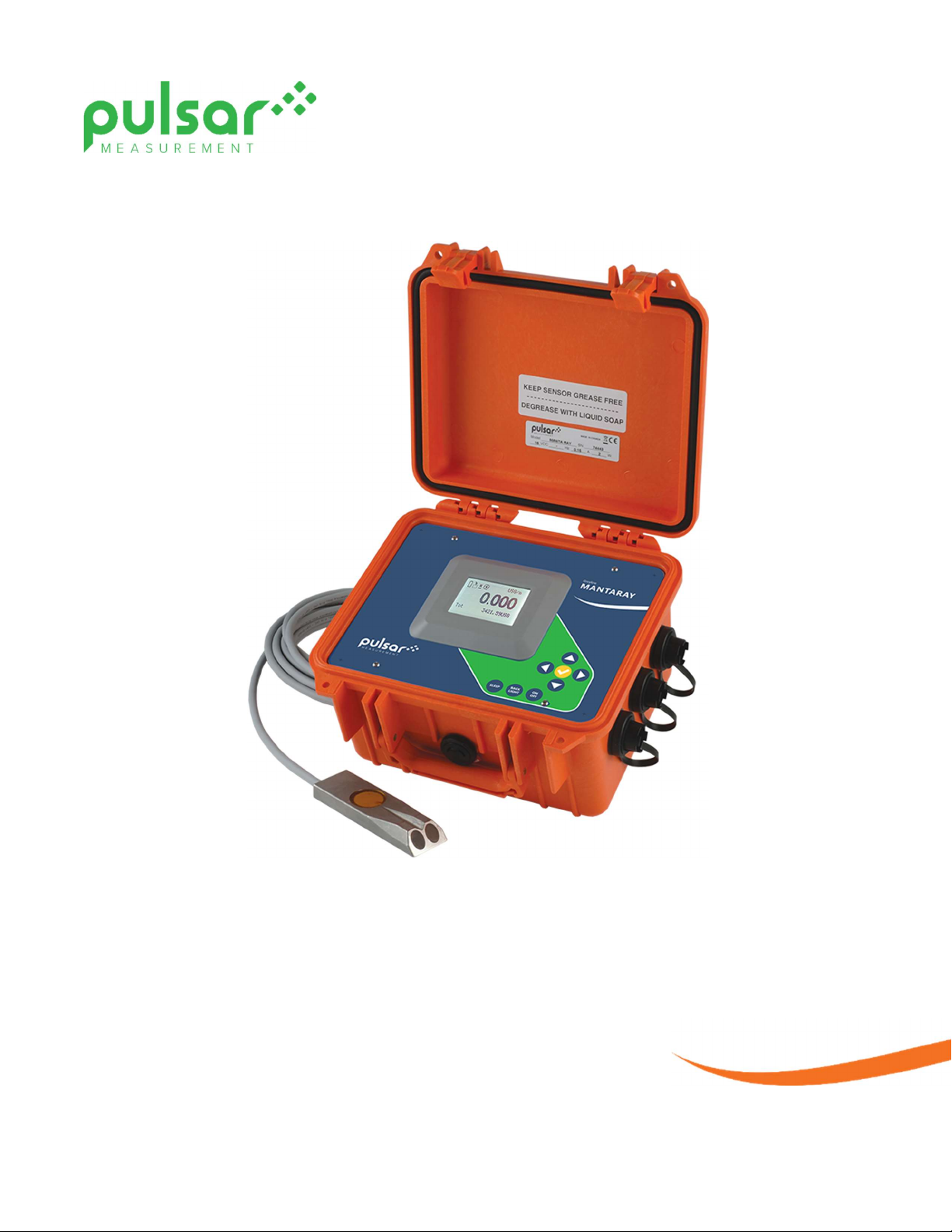
MantaRay
Instruction Manual
Manual Rev 3.1
Page 2

Note: This page has been left blank intentionally.
2
Page 3

PULSAR MEASUREMENT
CONTENTS
CONNECTIONS ................................................................................................................................................................................................. 4
KEYPAD SYSTEM ............................................................................................................................................................................................... 5
BATTERY ............................................................................................................................................................................................................... 5
PROGRAMMING MENU................................................................................................................................................................................. 6
ICONS ................................................................................................................................................................................................................... 7
MESSAGE ICON ................................................................................................................................................................................................. 8
STATUS ................................................................................................................................................................................................................. 8
PASSWORD ......................................................................................................................................................................................................... 9
UNITS/MODE ................................................................................................................................................................................................... 10
CALIBRATION ................................................................................................................................................................................................... 12
RELAY PARAMETERS ..................................................................................................................................................................................... 17
DATA LOGGING .............................................................................................................................................................................................. 19
RETRIEVING LOG FILE ................................................................................................................................................................................... 20
SPECIAL FUNCTIONS .................................................................................................................................................................................... 21
SIMULATION .................................................................................................................................................................................................... 22
INSTALLATION – SENSOR LOCATION ................................................................................................................................................... 23
BREAK-OUT BOX ............................................................................................................................................................................................ 29
SLEEP BUTTON AND TELEMETRY LOGGING INSTRUCTIONS ...................................................................................................... 30
APPLICATIONS HOTLINE ............................................................................................................................................................................. 32
PRODUCT RETURN PROCEDURE ............................................................................................................................................................. 32
SPECIFICATIONS ............................................................................................................................................................................................. 34
IMPORTANT NOTE: This instrument is manufactured and calibrated to meet product specifications. Please read this
manual carefully before installation and operation. Any unauthorized repairs or modifications may result in a
suspension of the warranty.
Available in Adobe Acrobat pdf format
3
Page 4
MANTARAY INSTRUCTION MANUAL
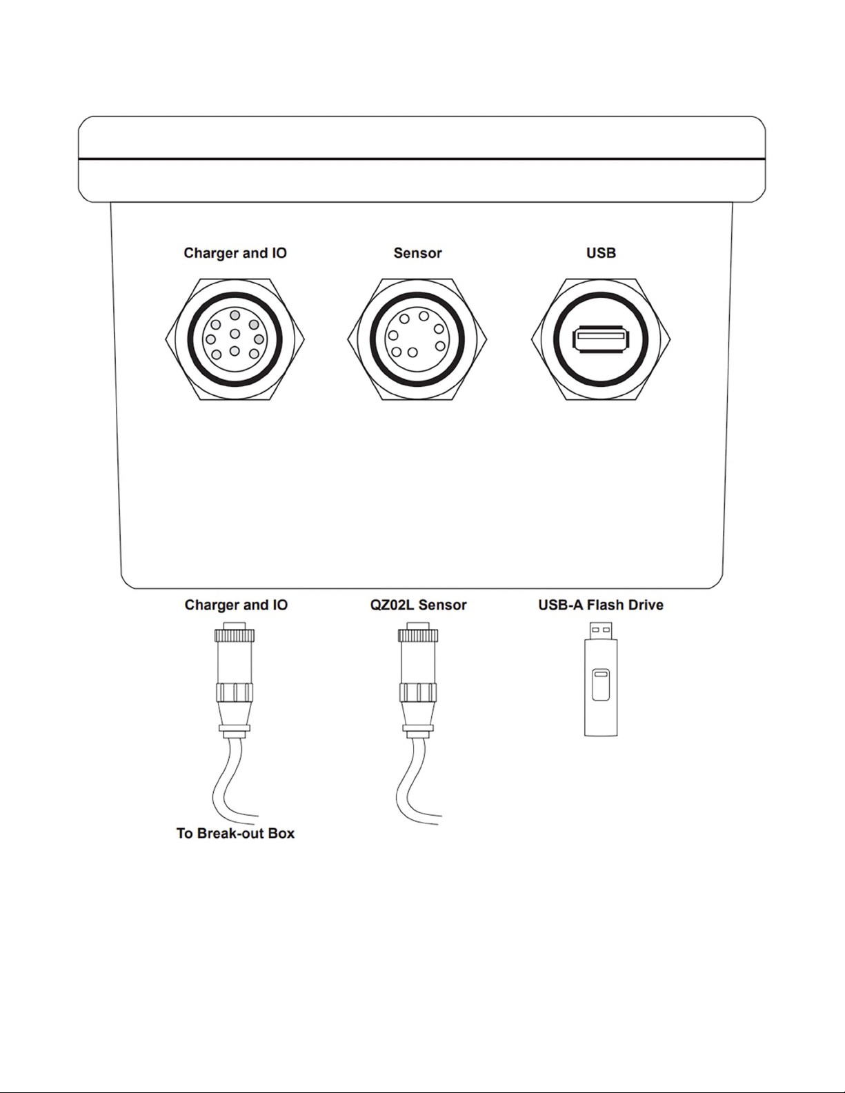
CONNECTIONS
NOTE: Sockets and plugs not drawn to scale.
4
Page 5
PULSAR MEASUREMENT
KEYPAD SYSTEM
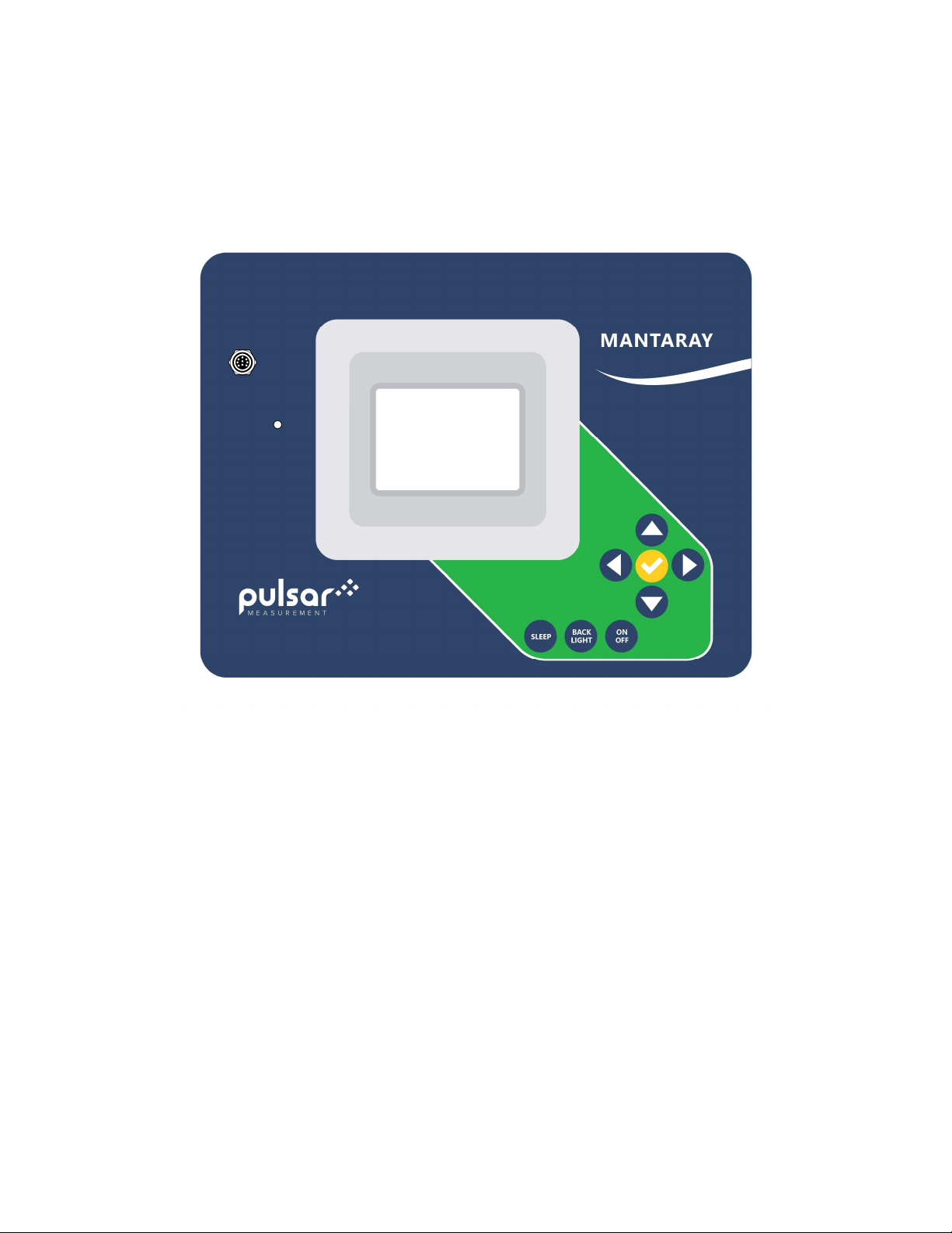
The MantaRay uses a menu system for general use and configuration. Arrows show the four directions to navigate
the menus. Pressing a corresponding keypad arrow will move to the next item in the direction shown. Move the
cursor (underline) under numerals and increase or decrease numerals with the and keys.
To store calibration values permanently (even through power interruptions), press .
BATTERY
- A built-in rechargeable NiMH battery supplies power for approximately 40 hours continuous operation when
fully charged. Your battery life may vary depending on factors like temperature, battery age, and backlight level.
- Display brightness is adjustable to conserve power. Press the “Back-Light” button to disable the backlight
completely.
- The MantaRay will switch off automatically when the battery is fully discharged.
- Full charge requires approximately 6 to 9 hours charging. The charge rate will be fastest between 0 and 90%, and
then it will slow down as it approaches 100% so that it is not over-charged.
- Sleep mode extends battery life for long-term data logging (30 days for 5 minute logging).
CHARGING BATTERY
A 16.5V AC-DC power module is supplied for battery charging and continuous use. The charger connects to the
faceplate of the MantaRay or to the exterior of the break-out box. Charge requires 6-9 hours when fully drained.
Solid battery icon indicates when battery is very close to fully charged (≥90%), and a power cable icon indicates
the battery is fully charged.
IMPORTANT: When the MantaRay is OFF and the charger is connected, the MantaRay will turn on and display a
charging animation. Pressing the power button or disconnecting the charger will place the meter in the normal
ON Main Screen. You must disconnect the charger and press the power button to return to and OFF state.
5
Page 6
MANTARAY INSTRUCTION MANUAL
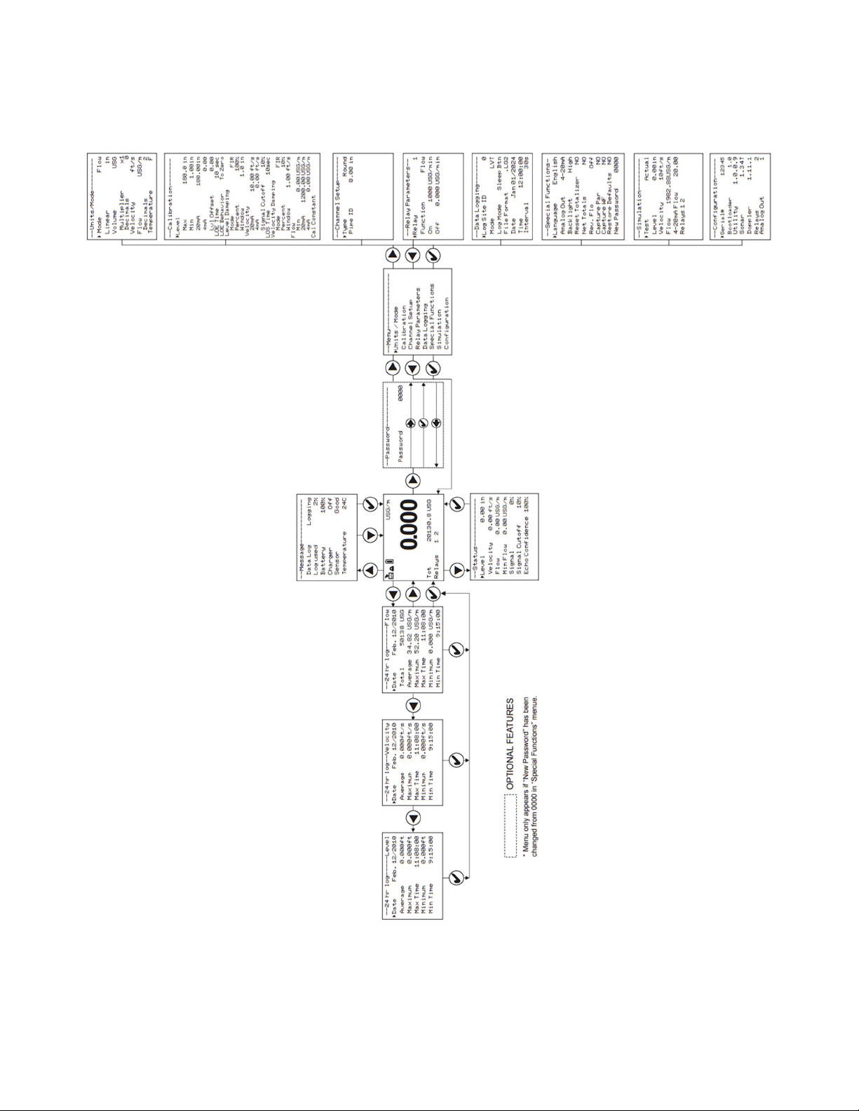
PROGRAMMING MENU
6
Page 7
ICONS
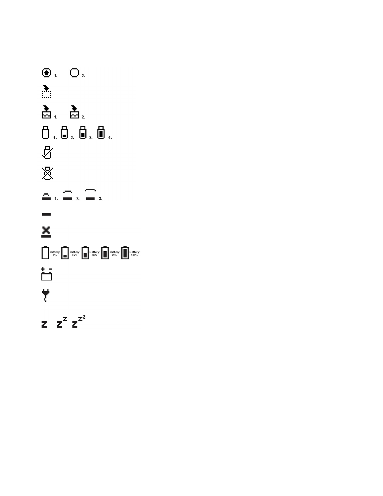
On the Main Screen, the following icons may present themselves:
A message is waiting. Press to view.
Data Logger is Stopped.
Data Logger is Running.
Data Log is transferring to USB drive.
Data Log transfer to USB drive complete.
Data Log transfer to USB failed.
Level ECHO OK.
Level sensor DRY. No ECHO, but sensor OK.
Level ECHO loss/no signal.
Battery fuel gauge levels, and minimum charge for each icon.
Meter is operating on external battery via break-out box.
Internal battery is fully charged.
Sleep Logging is enabled. Press the Sleep button to deploy into the
low-power sleep logging state. Press the Sleep button once in this
state to wake back up.
PULSAR MEASUREMENT
7
Page 8
MANTARAY INSTRUCTION MANUAL
MAIN DISPLAY
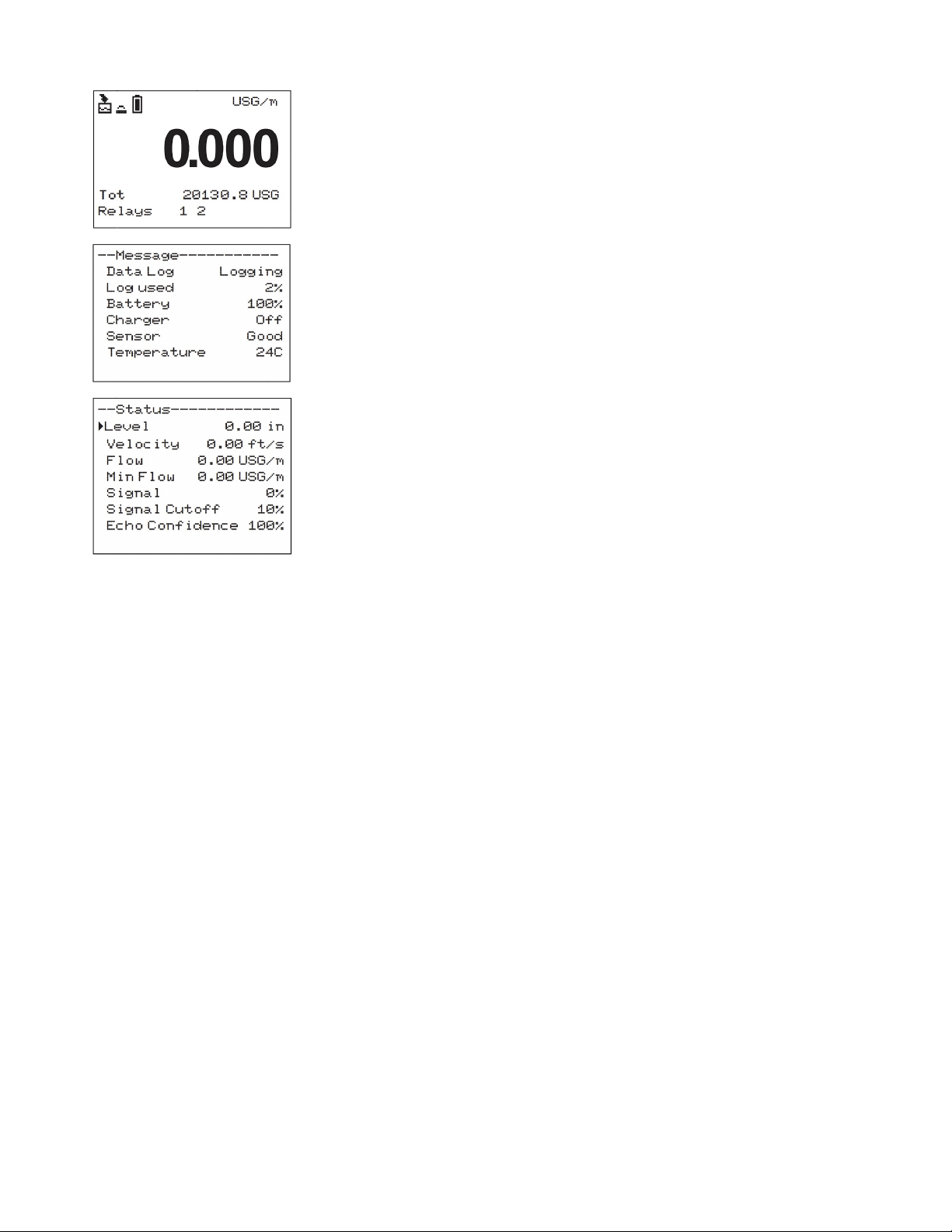
The main display shows the units selected from the Units/Mode menu, Flow
or Velocity rate being measured, TOTALIZER and RELAY states. The MantaRay
will start-up with this display.
MESSAGE ICON
Press from the main display to view Data Log state and percent used,
Battery fuel gauge, Charger connection state, Sensor Status (Good, Short,
Open, Dry, Echo Loss), and measured Temperature of the sensor. Press or
to return to the Main Display.
STATUS
Press from the Main Display to view instrument status. Press or to
return to the Main Display.
Level The current level measurement displayed in units
selected in the Units/Mode menu.
Velocity The current velocity measurement displayed in
units selected in the Units/Mode menu.
Flow The current flow rate measurement displayed in
units selected in the Units/Mode menu.
Min Flow Read-only value of the currently programmed
Min Flow in the Calibration menu. Any measured
flow less-than Min Flow will result in the Flow
reporting 0.
Signal The current signal strength for the Doppler
velocity measurement, 0-100%. Size of the Signal
Strength depends on velocity and quality of the
Doppler reflectors entrained in the flowing fluid.
Signal of 100% is typical, but Signal all the way
down to just above the default Signal Cutoff
(10%) is also acceptable for very slow moving
fluids.
Signal Cutoff Read-only value of the currently programmed
Signal Cutoff in the Calibration menu. Any Signal
less-than the Signal Cutoff will result in the
velocity stagnating or going to zero depending
on Calibration menu configuration.
Echo Confidence The current echo-confidence for the level
measurement. Echo confidence is the percent
ratio of the number of good echoes received
compared to the number of pulses sent to the
water surface. E.g. if 8 pulses are sent and 8
received, echo confidence is 100%. A level
measurement is considered good as long as Echo
Confidence is above 0%.
8
Page 9
PULSAR MEASUREMENT
24 HR LOG
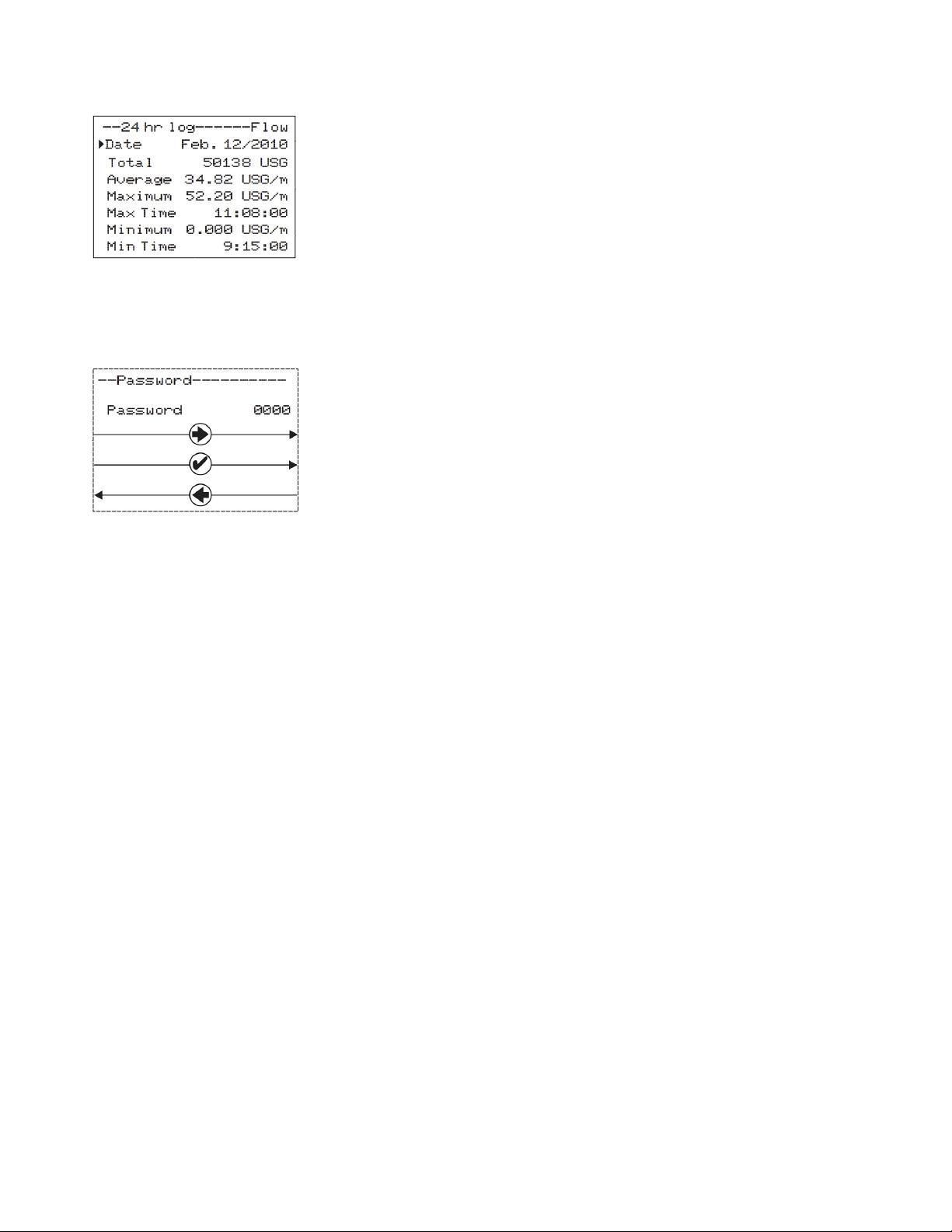
Press from the MAIN display to view a formatted flow report from
instruments with a built-in data logger. Press to pan through Flow, Velocity,
and Level summaries. Press to scroll down one day or repeatedly to scroll
to a specific date. Up to 365 days can be stored. The newest date will
overwrite the oldest. Press to return to the main display.
NOTE: Inserting a USB flash drive into the USB port of the MantaRay while on
this screen will cause the meter to download the 24 hr log data as a .CSV file
to the USB drive.
PASSWORD
The optional Password (a number from 0000 to 9999) prevents unauthorized
access to the main programming menus.
When a Password other than 0000 is set in the Special Functions menu, this
menu will appear and will require you to enter the password before you can
access the Main Menu. If the Password in the Special Functions menu is 0000,
this screen will not appear.
From the Main display press to get to Password or bypass this screen.
If a password is required, press to place the cursor under the first digit and
or to set the number, then to the second digit, etc. Press or to
proceed to the Main Menu.
A new password can be set by going the Special Functions menu and
adjusting the Password parameter.
9
Page 10
MANTARAY INSTRUCTION MANUAL
UNITS/MODE
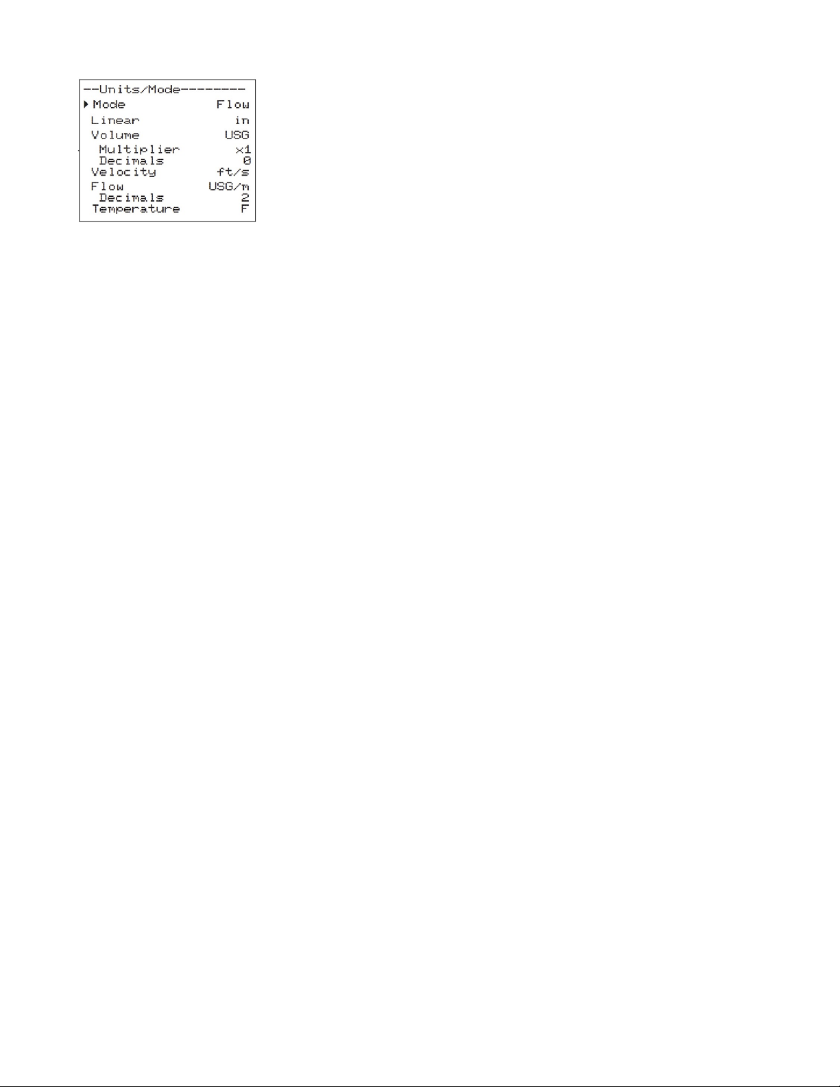
From the Main Menu, press the button while the cursor is on Units/Mode to
access this menu. The configuration parameters available in the Units/Mode
menu are described below. Use the or button to move the cursor up or
down, and the button to edit the selected parameter.
All parameter options in Units/Mode are list types. When changing a parameter,
use the or button to choose between the available selections. Press to
save your selection, or to cancel. Default values (US) are shown in the image to
the left.
Mode selects the measurement mode for the MantaRay. Choose between Flow,
Velocity, and Level.
Linear selects the engineering units for measuring level, or configuring
pipe/channel dimensions. Choose between in (inches), mm, m, and ft.
Volume selects the engineering units for measuring volume accumulation.
Choose between USG (US Gal), USMG (US Million Gal), IG (Imperial Gal), IMG
(Imperial Million Gal), m3, L, bbl (1 bbl = 42 USG), and ft3.
Volume Multiplier selects the multiplier to use for displaying accumulated
volume. E.g. an accumulated 1,000 USG with the Volume units configured for
USG and Multiplier of 1k would display as 1 USG x 1k. Choose between 1, 10,
100, 1k, 10k, 100k, and 1M.
Volume Decimals selects the number of decimals to display for accumulated
volume. E.g. an accumulated 1,000 USG with the Volume units configured for
USG, Multiplier of 1k, and Decimals of 2 would display as 1.00 USG x 1k. Choose
between 0, 1, 2, and 3.
Velocity selects the engineering units for velocity. Choose between ft/s, and m/s.
Flow selects the engineering units for flow rate. Choose between the options
listed in the table on the next page.
Flow Decimals selects the number of decimals to display for flow rate. E.g. a flow
rate of 1,000 USG/m with the Flow units configured for USG/m, and Decimals of
2 would display as 1,000.00 USG/m. Choose between 0, 1, 2, and 3.
Temperature selects the engineering units for temperature measurement.
Choose between Deg F, and Deg C.
10
Page 11
PULSAR MEASUREMENT
UNITS/MODE (CONT.)
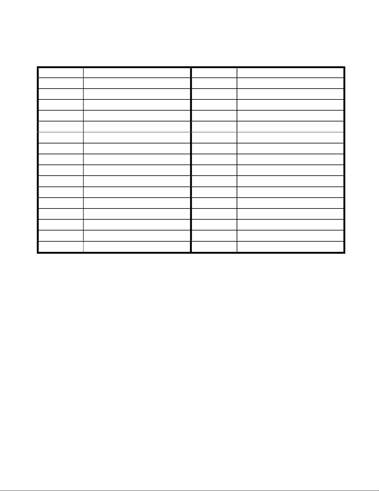
Available Flow Rate Engineering Units:
Abbreviation Description Abbreviation Description
USG/d US gallons per day L/d liters per day
USG/h US gallons per hour L/h liters per hour
USG/m US gallons per minute L/m liters per minute
USG/s US gallons per second L/s liters per second
ft3/d cubic feet per day m3/d cubic meters per day
ft3/h cubic feet per hour m3/h cubic meters per hour
ft3/m cubic feet per minute m3/m cubic meters per minute
ft3/s cubic feet per second m3/s cubic meters per second
bbl/d barrels per day (1 bbl = 42 USG) IG/d Imperial gallons per day
bbl/h barrels per hour (1 bbl = 42 USG) IG/d Imperial gallons per day
bbl/m barrels per minute (1 bbl = 42 USG)
bbl/d
barrels per second (1 bbl = 42 USG)
IG/d Imperial gallons per day
IG/d Imperial gallons per day
USMG/d US million gallons per day IMG/d Imperial million gallons per day
USMG/h US million gallons per hour IMG/h Imperial million gallons per hour
USMG/m US million gallons per minute IMG/m Imperial million gallons per minute
USMG/s US million gallons per second IMG/s Imperial million gallons per second
Note: the volume selection "bbl" denotes U.S. barrels.
11
Page 12
MANTARAY INSTRUCTION MANUAL
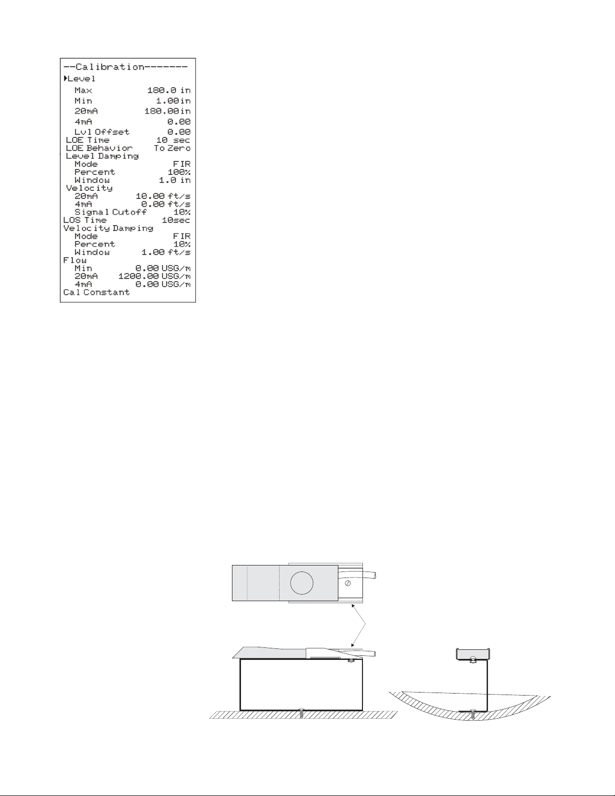
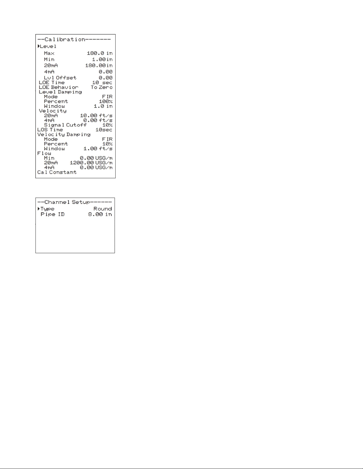
CALIBRATION
From the Main Menu, press the button while the cursor is on Calibration to
access this menu. The configuration parameters available in the Calibration
menu are described below. Use the or button to move the cursor up or
down, and the button to edit the selected parameter.
Some parameter options in Calibration are list types. When changing these
parameters, use the or button to choose between the available
selections. Press to save your selection, or to cancel.
Some parameter options in Calibration are numerical entry types. When
editing these parameters, use the or button to increment/decrement the
selected digit, and or to move the cursor position. A decimal point ( . ) or
negative ( - ) may also be available for some positions. Press to save your
input, or from the left-most position to cancel.
Default values are shown in the image to the left.
Level Max should be set to the maximum height the level should reach in the
system in units configured in the Units/Mode menu. If a Round pipe is
selected in the Channel Setup menu, then this value should be set to the
same value as the inside diameter of the pipe. The default of 180 inches (15ft)
is equal to the max level the QZ02L sensor can measure.
Level Min should be set to the minimum height the level should reach in the
system, in units configured in the Units/Mode menu. Minimum level for the
QZ02L sensor is 1 inch, however, this value could be set to a larger value if
you want to ignore levels greater than 1 inch.
Level 20mA is only displayed when the Mode in the Units/Mode menu is set
to Level. In this mode, the single 4-20mA output from the MantaRay will
respond to changes in level measurement. This parameter configures the level
equal to a 20mA output.
Level 4mA is only displayed when the Mode in the Units/Mode menu is set
to Level. In this mode, the single 4-20mA output from the MantaRay will
respond to changes in level measurement.
Level Offset is used when the QZ02L sensor is not mounted directly at the
bottom of the channel or pipe, oftentimes when you want to prevent the
sensor from being covered with mud/silt/debris.
12
SENSOR
LEV EL
SEN SOR
TOP VIEW
SIDE VIEW
USE THE MB-QZ
STAINLESS STEEL
MOUNTING BRACKET
(SUPPLIED)
SENSOR ELEVATED
ABOVE FLOOR OF
PIPE OR CHANNEL
SENSOR
U-SHAPE STAINLESS STEEL
18 GA. RECOMMENDED
HEIGHT AS REQUIRED
Page 13
PULSAR MEASUREMENT
CALIBRATION (CONT.)
LOE Time is used to suppress a loss in level because of air or debris in the
system. The LOE Time will cause the meter to hold the last valid level reading
when a loss of echo occurs until the LOE Time is expired, at which point the
meter will produce a Loss of Echo alarm message, and the level reading on
the meter will respond according to the LOE Behavior parameter. The default
value for LOE Time is 10 seconds. If you desire that the meter respond quicker
or slower to a Loss of Echo, adjust the LOE Time down or up, respectively. The
MantaRay will automatically being reading level again should the condition
causing the echo loss to go away, and a loss of echo will again require the
LOE Time to count down.
LOE Behavior is used to select behavior for the level measurement when a
loss of echo occurs (after LOE Time expires). Options are either To Zero, which
means the meter will report 0 for the level measurement, or Hold, where the
meter will hold the last valid level reading before the loss of echo occurred.
The meter will therefore use that level for calculating flow should a velocity
also be present.
Level Damping Mode selects the damping algorithm used for level
measurement. Options are FIR, LOW PASS, and OFF.
When new measured levels are outside the Window of the damped output
(value currently reported by the meter), the FIR filter will reduce the number
of measurements used in the damping average so that a faster response can
be made to the sudden change in level.
The LOW PASS filter will ignore new measured levels outside the Window of
the damped output, while holding the damped output until there are enough
consecutive measurements outside the Window to cause a sudden stepresponse to the new measured value.
While measured levels are within the Window of the damped output (the
current level measurement), both the FIR and LOW PASS filter behave the
same.
Level Damping Percent selects the size of the damping average. Larger
values average more consecutive readings together and cause the meter to
be less responsive to large changes in level measurement. Lower values
reduce the damping average size and cause the meter to be more responsive
to large changes in level measurement.
Level Damping Window sets a boundary around the damped output
(currently reported level), where if the next measured value falls outside the
current value ± window, the meter will make a more rapid response to the
new value (Damping Mode = FIR), or will hold the last reading until enough
consecutive values are outside the window and then make a step response to
the new value (Damping Mode = LOW PASS).
Velocity 20mA is only displayed when the Mode in the Units/Mode menu is
set to Velocity. In this mode, the single 4-20mA output from the MantaRay
will respond to changes in velocity measurement. This parameter configures
the velocity equal to a 20mA output.
13
Page 14
MANTARAY INSTRUCTION MANUAL
CALIBRATION (CONT.)
Velocity 4mA is only displayed when the Mode in the Units/Mode menu is
set to Velocity. In this mode, the single 4-20mA output from the MantaRay
will respond to changes in velocity measurement. This parameter configures
the velocity equal to a 4mA output.
Velocity Signal Cutoff sets a cutoff where any measured velocity Signal
Strength which is less than the Signal Cutoff will cause the meter to report 0
velocity. This value can be lowered to increase sensitivity in very low flow
situations, at the risk of allowing electrical noise to be measured as actual
flow. This value can be raised to decrease sensitivity, useful for when flow
occurs Signal Strength is very high, yet random noise levels with no flow are
above the default value of 10%. E.g. for an application where when flow is
present, Signal Strength is 100%, yet with no flow the Signal Strength is 50%,
setting the Signal Cutoff to 60% will suppress the unwanted noise with no
flow yet not interfere with the actual velocity measurement when flow is
present.
LOS Time is used to suppress a loss in velocity because of a disturbance
which may interfere with the velocity measurement, like a sudden decrease in
air/solids in the fluid or a sudden increase in turbulence which causes an
inconclusive Doppler measurement. The LOS Time will cause the meter to
hold the last valid velocity reading when a loss of signal occurs until the LOS
Time is expired, at which point the meter will report 0 for the velocity
measurement. The default value for LOS Time is 10 seconds. If you desire that
the meter respond quicker or slower to a signal loss, adjust the LOS Time
down or up, respectively. The MantaRay will automatically begin reading
velocity again should the condition causing the signal loss to go away, and a
loss of signal will again require the LOS Time to count down.
Velocity Damping Mode selects the damping algorithm used for velocity
measurement. Options are FIR, LOW PASS, and OFF.
When new measured velocities are outside the Window of the damped
output (value currently reported by the meter), the FIR filter will reduce the
number of measurements used in the damping average so that a faster
response can be made to the sudden change in velocity.
The LOW PASS filter will ignore new measured levels outside the Window of
the damped output, while holding the damped output until there are enough
consecutive measurements outside the Window to cause a sudden stepresponse to the new measured value.
While measured levels are within the Window of the damped output (the
current level measurement), both the FIR and LOW PASS filter behave the
same.
Velocity Damping Percent selects the size of the damping average. Larger
values average more consecutive readings together and cause the meter to
be less responsive to large changes in level measurement. Lower values
reduce the damping average size and cause the meter to be more responsive
to large changes in velocity measurement.
14
Page 15
PULSAR MEASUREMENT
CALIBRATION (CONT.)
Velocity Damping Window sets a boundary around the damped output
(currently reported velocity), where if the next measured value falls outside
the current value ± window, the meter will make a more rapid response to the
new value (Damping Mode = FIR), or will hold the last reading until enough
consecutive values are outside the window and then make a step response to
the new value (Damping Mode = LOW PASS).
Flow Min sets a cutoff where if measured flow is less than the Min Flow, the
reading on the LCD display and output signals will report 0.
Flow 20mA is only displayed when the Mode in the Units/Mode menu is set
to Flow. In this mode, the single 4-20mA output from the MantaRay will
respond to changes in flow measurement. This parameter configures the flow
equal to a 20mA output.
Flow 4mA is only displayed when the Mode in the Units/Mode menu is set to
Flow. In this mode, the single 4-20mA output from the MantaRay will respond
to changes in flow measurement. This parameter configures the flow equal to
a 4mA output.
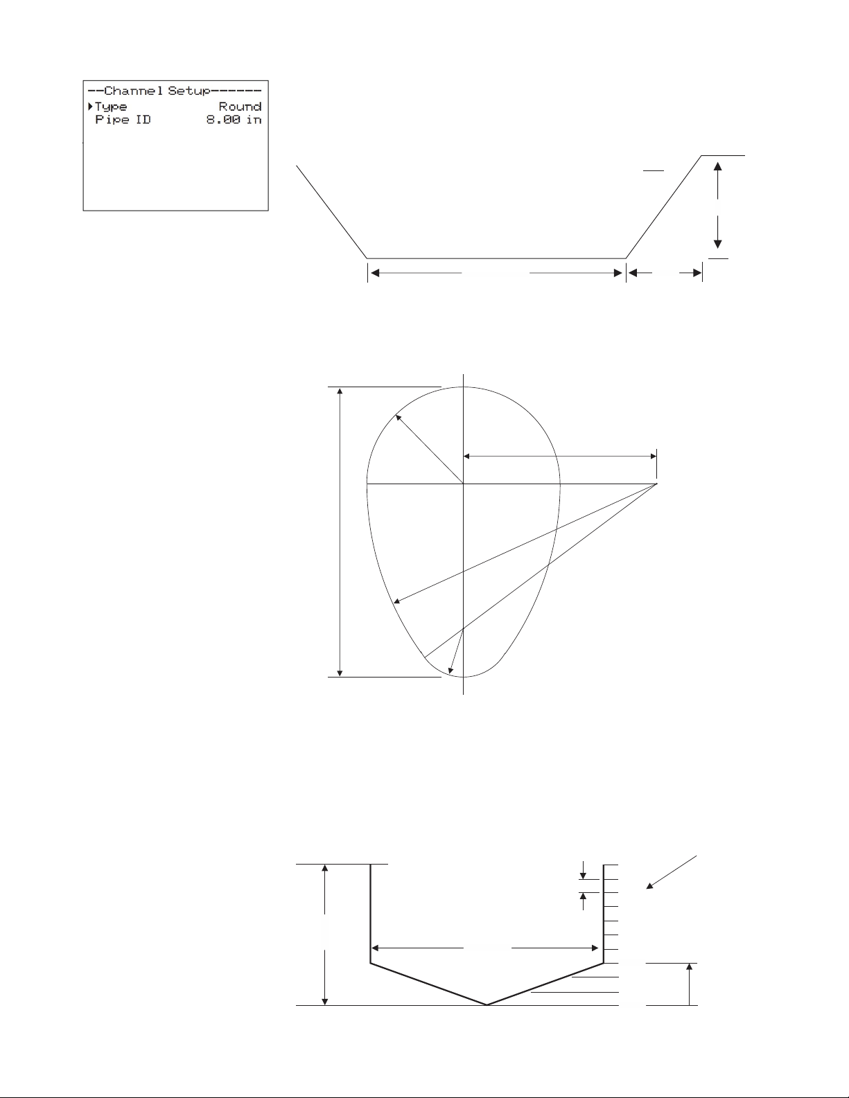
CHANNEL SETUP
From the Main Menu, press the button while the cursor is on Channel
Setup to access this menu. The configuration parameters available in the
Channel Setup menu are described below. Use the or button to move
the cursor up or down, and the button to edit the selected parameter.
Some parameter options in Channel Setup are list types. When changing
these parameters, use the or button to choose between the available
selections. Press to save your selection, or to cancel.
Some parameter options in Channel Setup are numerical entry types. When
editing these parameters, use the or button to increment/decrement the
selected digit, and or to move the cursor position. A decimal point ( . )
may also be available for some positions. Press to save your input, or
from the left-most position to cancel.
Default values are shown in the image to the left.
Type is used to select the shape of the channel or pipe. Based on this
selection, additional parameter options not shown in the image to the left
may appear. Select from the following:
Round
Select Round for open pipes. Set Pipe ID to the inner diameter
of the pipe.
Rectangle
Select Rectangle for rectangular channels. Enter the channel
width.
Trapezoid
Select Trapezoid for trapezoidal shaped channels. Specify the
Width and Slope of the channel as shown in the following
illustration.
15
Page 16
MANTARAY INSTRUCTION MANUAL
SLOPE =
x
INCREMENT #
DIVISION
HEIGHT
CHANNEL SETUP (CONT.)
Trapezoid (Cont.)
TRAPEZOIDAL
CHANNEL
y
x
WIDTH
y
Egg Select Egg for egg shaped channels. Enter the Max Height of the
channel.
R
= 3R
3R
R/2
2R
16
Custom
MAX
HEIGHT
Define Max Height of the channel, and number of Divisions for
defining Width at each Increment. Level displays the level of the
channel for each Increment and Width entry. Use Reset Data to
clear the custom channel if you made a mistake or using a new
custom channel.
10
9
8
7
6
WIDTH
5
4
3
2
1
0
LEVEL
Page 17
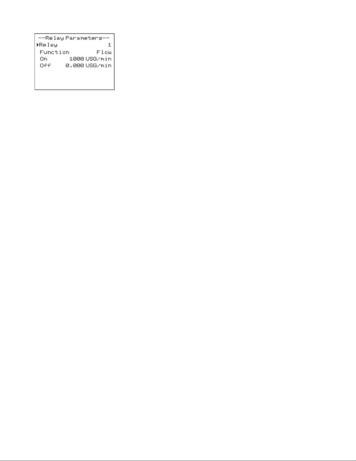
RELAY PARAMETERS
From the Main Menu, press the button while the cursor is on Relay
Parameters to access this menu. The configuration parameters available in the
Relay Parameters menu are described below. Use the or button to move
the cursor up or down, and the button to edit the selected parameter.
Some parameter options in Relay Parameters are list types. When changing
these parameters, use the or button to choose between the available
selections. Press to save your selection, or to cancel.
Some parameter options in Relay Parameters are numerical entry types.
When editing these parameters, use the or button to
increment/decrement the selected digit, and or to move the cursor
position. A decimal point ( . ) may also be available for some positions. Press
to save your input, or from the left-most position to cancel.
Relay is used to select which of the two relay outputs you wish to
reconfigure. After choosing either 1 or 2, use the Function parameter to select
how you wish to use that relay.
Function is used to set the behavior of the relay selected at the Relay
parameter. Choose between the following functions. Depending on function,
additional options will appear/disappear.
On
Level
Velocity
Will set the associated Relay ON.
Will provide an ON and OFF setpoint for level alarm.
When ON>OFF, the level alarm functions like a high level
alarm. When measured level is greater than ON setpoint,
the relay will turn on, and the relay will turn off when
measured level goes below OFF setpoint. When ON<OFF,
the level alarm will function like a low level alarm instead
with reverse logic as described above. LOE mode is used
to choose how the relay will behave when a loss of echo
occurs. Note: the LOE mode behavior will override any
behavior which would occur due to the LOE Behavior in
the Calibration menu. E.g. if the meter is set to HOLD for
LOE Behavior, and ON for LOE mode, this relay will turn on
regardless if the held level would have the relay off.
Like Level, will provide an ON and OFF setpoint for
velocity alarm. When ON>OFF, the velocity alarm
functions like a high velocity alarm. When measured
velocity is greater than ON setpoint, the relay will turn on,
and the relay will turn off when measured velocity goes
below OFF setpoint. When ON<OFF, the velocity alarm
will function like a low velocity alarm instead with reverse
logic as described above.
PULSAR MEASUREMENT
17
Page 18
MANTARAY INSTRUCTION MANUAL
RELAY PARAMETERS (CONT.)
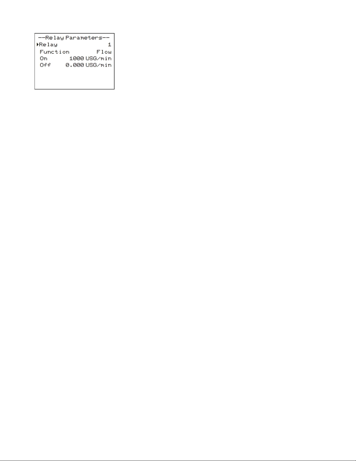
Flow
Like Level and Velocity, will provide an ON and OFF
setpoint for flow alarm. When ON>OFF, the flow alarm
functions like a high flow alarm. When measured flow is
greater than ON setpoint, the relay will turn on, and the
relay will turn off when measured flow goes below OFF
setpoint. When ON<OFF, the flow alarm will function like a
low flow alarm instead with reverse logic as described
above.
Direction Used to set the relay to latch ON or OFF depending on
measured flow direction. A requirement for this to work is
to have Rev Flow in the Special Functions menu set to ON
or INVERT. When flow is negative on the main screen, the
relay will turn ON. When flow is positive, the relay will turn
OFF. There is a couple second delay built-in to the relay
changing state, so that there is no chatter near 0 flow
conditions.
Pulse Sets the amount of volume which needs to accumulate for
a relay pulse to occur, in units configured in the
Units/Mode menu. A relay pulse is a 350ms in duration.
Minimum time between pulses is 2.25 seconds. Use this
output to accurately measure volume without having to
integrate the 4-20mA output over time.
Note: The volume accumulation starts from when the new
Pulse value is accepted with the button. E.g. if the
totalizer was 525 gallons when the Pulse was set to 100
gallons, the next pulse output would occur at 625 gallons.
Off Turns the selected relay OFF.
18
Page 19
PULSAR MEASUREMENT
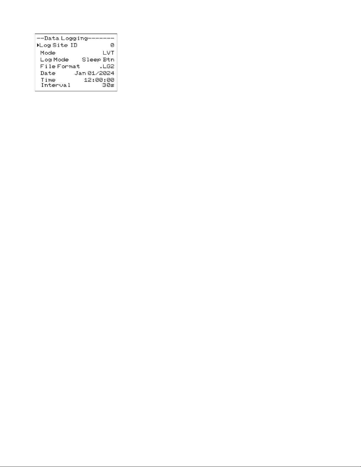
DATA LOGGING
From the Main Menu, press the button while the cursor is on Data Logging
to access this menu. The configuration parameters available in the Data
Logging menu are described below. Use the or button to move the
cursor up or down, and the button to edit the selected parameter.
Some parameter options in Data Logging are list types. When changing these
parameters, use the or button to choose between the available
selections. Press to save your selection, or to cancel.
Some parameter options in Data Logging are numerical entry types. When
editing these parameters, use the or button to increment/decrement
the selected digit, and or to move the cursor position. A decimal point
( . ) may also be available for some positions. Press to save your input, or
from the left-most position to cancel.
Log Site ID is used to enter a number from 00 to 99. The site ID will become
part of the downloaded file name to help distinguish downloads from
different instruments.
Mode is used to select between LVT, Flow, Velocity, and Level mode. Default
is LVT. LVT logs flow rate, level, velocity, and temperature simultaneously.
Flow, Velocity, and Level modes only log the parameter described. It is
suggested to use LVT since it is useful to see the behavior of level and
velocity independently in order to understand flow meter performance. The
Mode cannot be changed when the meter is Logging, you must Stop or
Delete the log first.
Log Mode is used to select the sleep mode behavior of the MantaRay. When
Sleep Btn is selected, the SLEEP button on the front of the meter is used to
put the MantaRay in a low power state, where it will periodically “wake-up”
based on the Interval, and log data before going back to the low power state.
This is used to greatly increase battery life for longer term studies. When Log
Mode is set to Sleep Btn, you will also see the “Zzz” animation on the main
display. When set to Telemetry, pressing the SLEEP button on the meter will
put the meter into a low-power state, but instead of automatically “waking
up” at the proper interval, the MantaRay will wait for a signal from an external
telemetry device, like a SignalFire RANGER, then go back to a low-power
state after being signaled. When in Telemetry mode, there is no “Zzz” on the
main display.
File Format allows you to choose .LG2 to download data in .lg2 format for
viewing on Greyline Logger software. Choose .CSV to download data in .csv
format for import directly to Excel. This menu option can be changed at any
time without adversely affecting existing data.
Date allows you to set the date in MMM DD, YYYY format. It is suggested
that you Delete and Start the log over again after changing the date.
Time allows you set the time in HH:MM:SS format, from 00:00:00 to 23:59:59.
It is suggested that you Delete and Start the log over again after changing
the time.
19
Page 20
MANTARAY INSTRUCTION MANUAL
DATA LOGGING (CONT.)
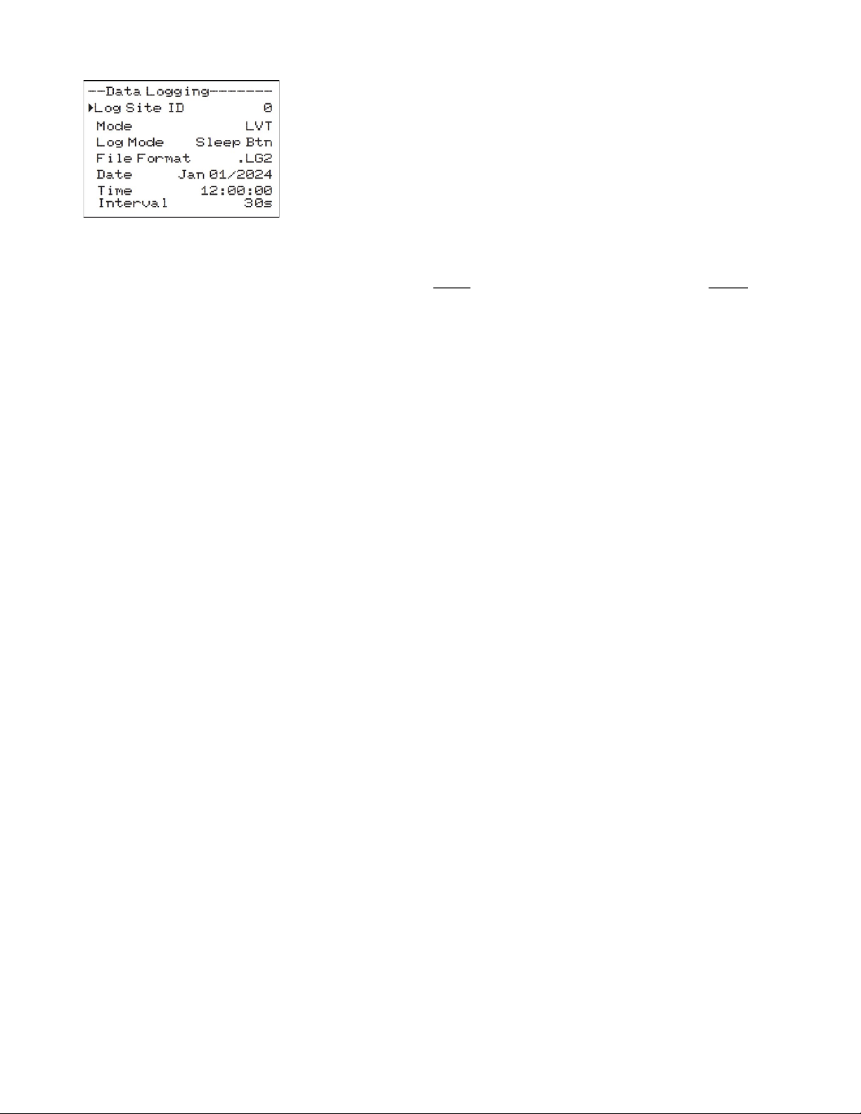
Interval is used to set the length of time between data log entries. Choose
between 10s, 30s, 1min, 2min, 5min, 10min, 15min, 30min, and 60min.
IMPORTANT: Using the SLEEP button when Log Mode is Sleep Btn or
Telemetry will only work when the Interval is 30s or greater. This is because
the amount of time the meter will “wake up” to make a measurement in the
low-power state is longer than the shortest interval – 10s.
Data Log is used to Stop, Start or Delete the log file.
Important Note: You MUST Delete an old log and Start a new log AFTER
having made changes to Log Site ID, Mode, Date, Time and/or Interval for
those changes to be applied.
Important Note: Changing any of the parameters in the Units/Mode menu
will start a new log. It is recommended that you Delete and start a new log
after changing any Units/Mode settings.
RETRIEVING LOG FILE
Plug a USB Flash Drive (one is included with the AVFM 6.1) into the USB
output port on the side of the meter. The main display will show the data
download icon until the log file is transferred to the memory card, at which
point it will show a completed (check mark) icon. The USB flash drive may be
removed when the icon for a successful download appears.
Download filenames will appear in this format: MRAY__0A.LG2, where the “0”
will automatically change to match the Log Site ID from the Data Logging
menu, “A” will increment to “B” and so-on, for each subsequent download of
the data log from one specific meter, and “.LG2” is for File Format LG2 or
“.CSV” for File Format CSV.
Note: Downloading files in .lg2 format will take approximately 35 seconds
per 1% of internal log memory used.
20
Downloading files in .csv format will take approximately 8 minutes per
1% of internal log memory used.
Note: Opening .LG2 files: Install Greyline Logger (available for free at
pulsarmeasurement.com) on your PC or laptop. Select File/Open/Instrument
Log (.log) to open the log file from your USB flash drive. Data can also be
converted to .CSV via Greyline Logger software.
Note: Opening .CSV files: Use a datasheet program such as Microsoft Excel®
to import data in a comma delimited format. Use Excel to manipulate or
graph data.
Page 21
PULSAR MEASUREMENT
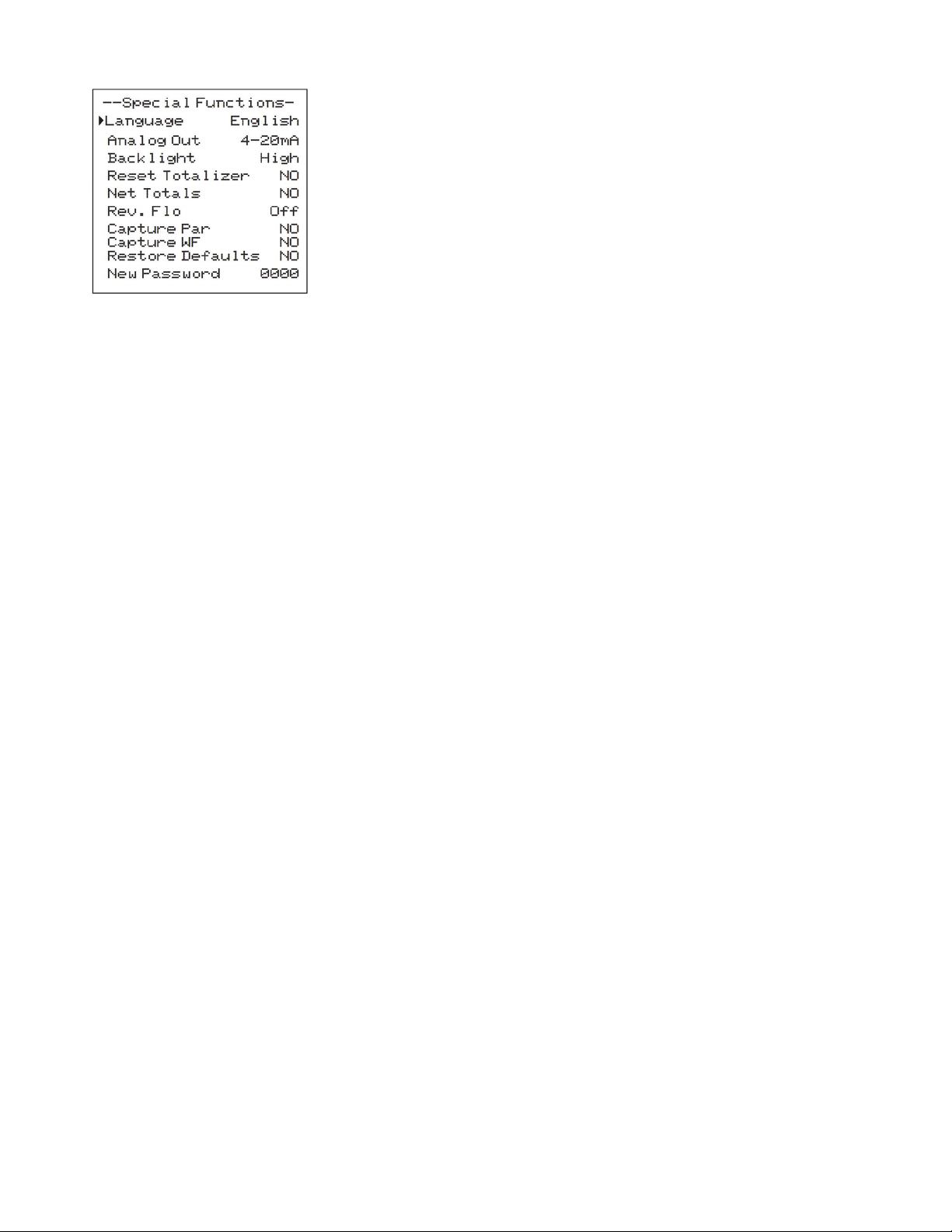
SPECIAL FUNCTIONS
From the Main Menu, press the button while the cursor is on Special
Functions to access this menu. The configuration parameters available in the
Special Functions menu are described below. Use the or button to move
the cursor up or down, and the button to edit the selected parameter.
Some parameter options in Special Functions are list types. When changing
these parameters, use the or button to choose between the available
selections. Press to save your selection, or to cancel.
Some parameter options in Special Functions are numerical entry types.
When editing these parameters, use the or button to
increment/decrement the selected digit, and or to move the cursor
position. A decimal point ( . ) may also be available for some positions. Press
to save your input, or from the left-most position to cancel.
Language is used to change the language for text on the MantaRay. Choose
between English, Spanish (Español), and French (Français).
Analog Out is used to select between 4-20mA and 0-5V for the type of
signal sent out from the analog output on the MantaRay, available in the
breakout I/O box. Both the 4-20mA and 0-5V are internally powered by the
MantaRay.
Backlight is used to change the backlight level for the LCD display, for
different environmental lighting levels or to conserve battery via a lower
backlight level.
Reset Totalizer is used to reset the volume totalizer on the main display to 0.
Choose YES to perform the reset, or NO or to cancel.
Net Totals is used to make the main volume totalizer on the meter a net
totalizer, meaning positive flows will make the volume go up, while negative
totals will make the totals go down. This parameter should only be used
when Rev Flow is ON or INVERT.
Rev. Flo is used to enable reverse flow measurement on the MantaRay (ON),
or to reverse the orientation of positive and negative flow on the MantaRay
(INVERT).
Capture Par can be enabled in order to prepare the configuration
parameters in a .CSV file so that it can be emailed. After selecting YES, wait
for Insrt USB to appear, then insert your USB flash drive into the plug on the
MantaRay, at which point the meter will flash SAVING on the screen a couple
times then return to NO. When this happens, you are OK to remove the flash
drive. The parameter file will have a filename format of MANT_P0A.CSV.
Capture WF can be enabled in order to prepare a digital copy of the level
waveform, plus a copy of the configuration parameters, to a .CSV file so that
it can be emailed. After selecting YES, the meter will flash WORKING. Wait for
Insrt USB to appear, then insert your USB flash drive into the plug on the
MantaRay, at which point the meter will flash SAVING on the screen a couple
times then return to NO. When this happens, you are OK to remove the flash
drive. The parameter file will have a filename format of MANT_W0A.CSV.
21
Page 22
MANTARAY INSTRUCTION MANUAL
SPECIAL FUNCTIONS (CONT.)
Restore Defaults can be used to return all programming parameters, except
limited parameters like Cal Constant, to their default values. Choose the US
option to restore parameters to Imperial units, or Metr to restore values to
metric/SI units.
New Password is used to configure a password to protect against
unauthorized access to the Main Menu for programming. Any time the value
is set to something other than 0000, the user will be prompted to enter the
password when going from the Main Display to the Main Menu using the
button from the Main Display.
SIMULATION
From the Main Menu, press the button while the cursor is on Simulation to
access this menu. The configuration parameters available in the Simulation
menu are described below. Use the or button to move the cursor up or
down, and the button to edit the selected parameter.
Some parameter options in Simulation are list types. When changing these
parameters, use the or button to choose between the available
selections. Press to save your selection, or to cancel.
Some parameter options in Simulation are numerical entry types. When
editing these parameters, use the or button to increment/decrement
the selected digit, and or to move the cursor position. A decimal point
( . ) may also be available for some positions. Press to save your input, or
from the left-most position to cancel.
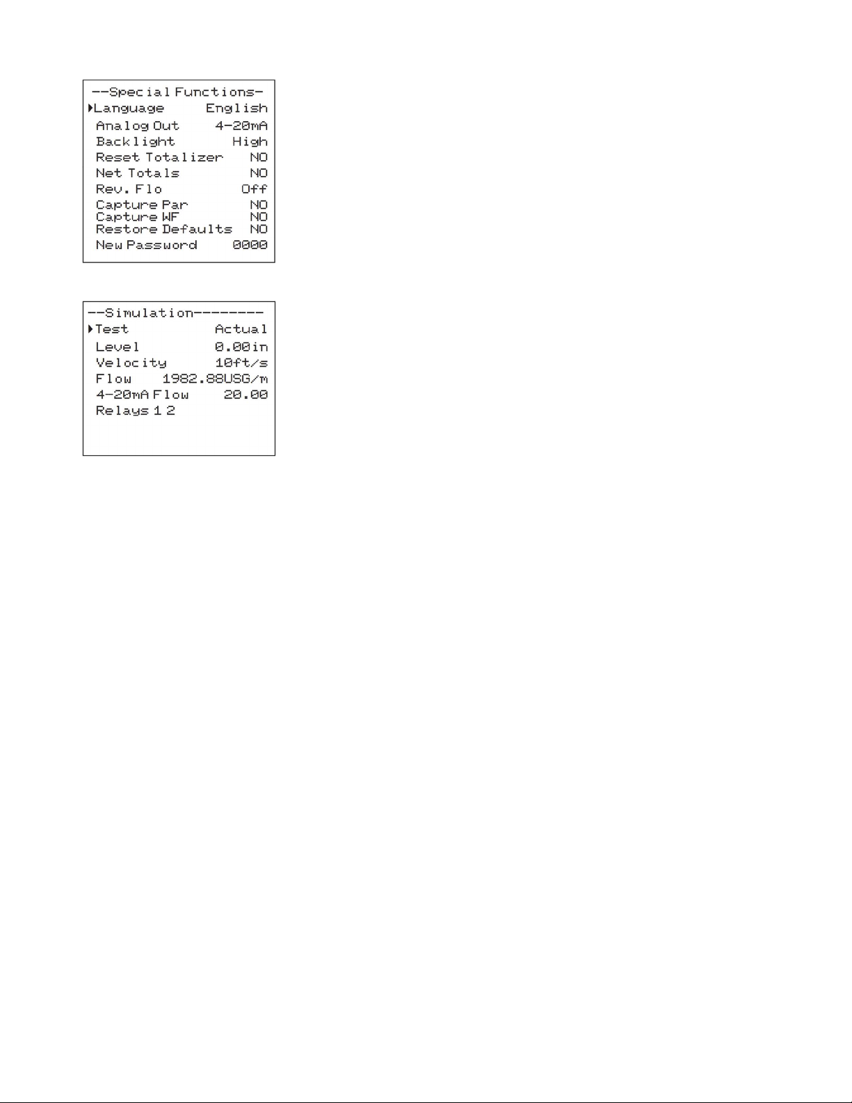
Test is used to choose how to exercise the 4-20mA/0-5V analog output as
well as Relays 1 and 2. Actual will populate the Level, Velocity, and Flow with
values from the actual measurement before entering the Simulation menu.
Change to Minimum to set the Level, Velocity, and Flow to their Min levels
(4mA/0V). Change to Maximum to set the Level, Velocity, and Flow to their
Max levels (20mA/5V). While Test = Actual, you can also enter the Level,
Velocity, and Flow parameters and manually change their values.
4-20mA/0-5V is a read-only view of the analog output for
Level/Velocity/Flow, depending on Units/Mode configuration. The analog
output will respond to simulated values so that it can be tested
independently of the actual measurement. Exiting the simulation menu will
cause the analog output to respond according to the actual measurement.
Relays 1 2 is a read-only view of the relay state (a black numeral with white
background is OFF, and a white numeral with black background is ON).
Relays will respond to simulated values so that their logic can be tested
independently of the actual measurement. Exiting the simulation menu will
cause the relays to respond according to the actual measurement.
22
Page 23
PULSAR MEASUREMENT
INSTALLATION – SENSOR LOCATION
For the most accurate flow measurement possible, careful consideration should be made to the placement of the
sensor in relation to flow disturbances. In general, the best accuracy will occur where flow is evenly distributed
across the channel/pipe and free of turbulence.
Specific installation considerations are listed and discussed in more detail below.
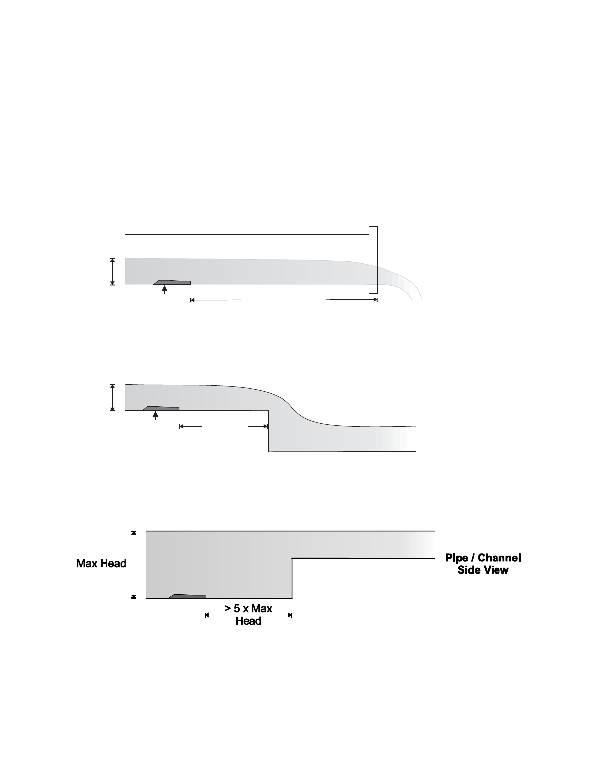
1. Open Discharges or Pipe/Channel Outfalls
When the QZ02 sensor is to be mounted in front (upstream) of an open discharge or pipe/channel outfall, the
sensor should be placed at least 5 times the maximum head level in front of the outfall:
Max Head
Max Head
QZ02
Sensor
QZ02
Sensor
5 x Max
Head
Pipe / Channel
Side View
5 x Max Head
Pipe / Channel
Side View
23
Page 24
MANTARAY INSTRUCTION MANUAL
QZ02
INSTALLATION – SENSOR LOCATION (CONT.)
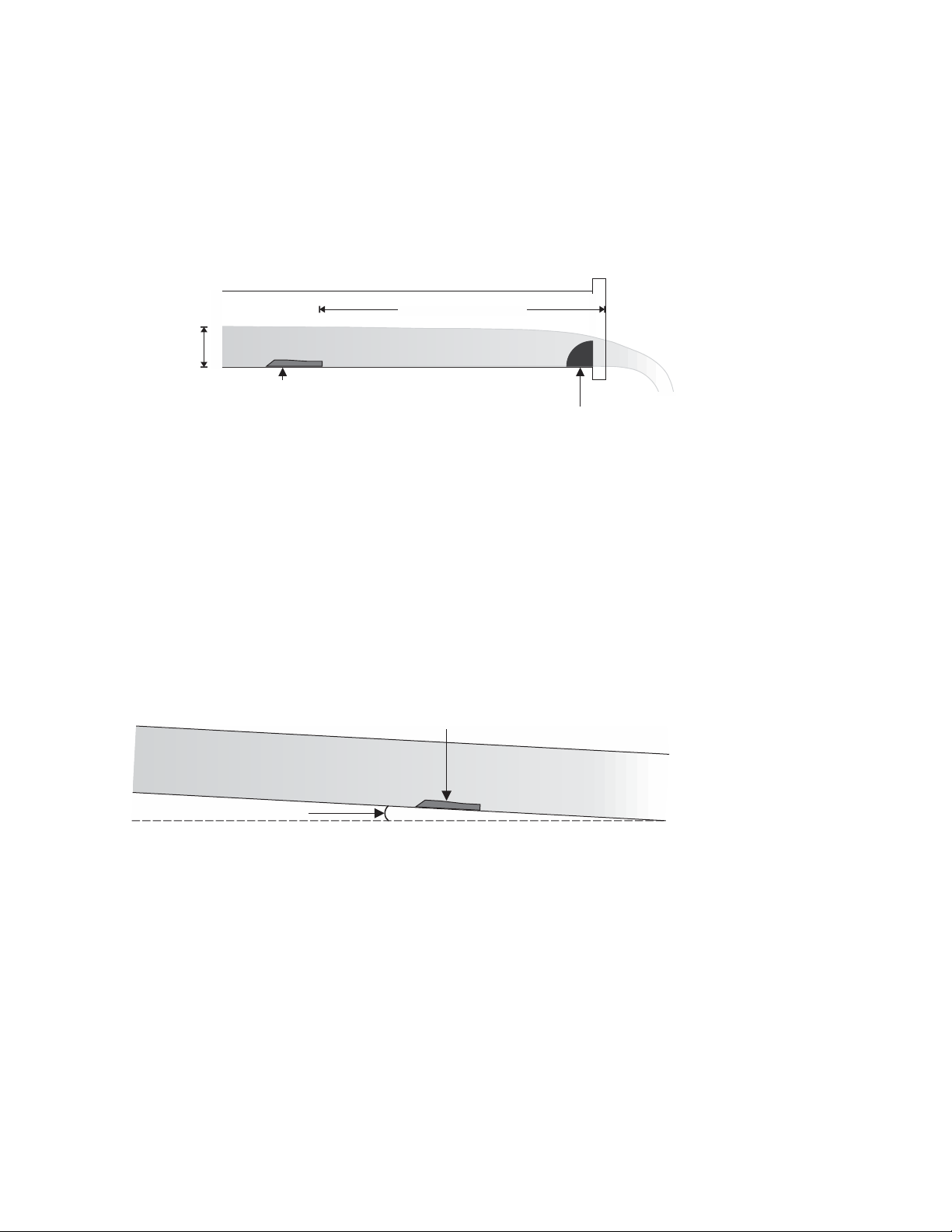
2. Hydraulic Dams
When the QZ02 sensor is to be mounted in front (upstream) of a hydraulic dam, or a Greyline VD pipe dam,
the sensor should be placed at least 20 inches in front of the dam.
Important note: Best results when using a dam occur when the pipe/channel grade is less than 1%.
5 x Max Head
Max Head
Pipe / Channel
Side View
QZ02
Sensor
Hydraulic Dam
or
VD Pipe Dam
3. Pipe Grade
The pipe/channel in which the QZ02 sensor is mounted should not have a grade exceeding 3%. If a
pipe/channel dam is used, slope should be less than 1% for best results.
Sensor
Pipe / Channel
Side View
Grade 3%
24
Page 25
PULSAR MEASUREMENT
INSTALLATION – SENSOR LOCATION (CONT.)
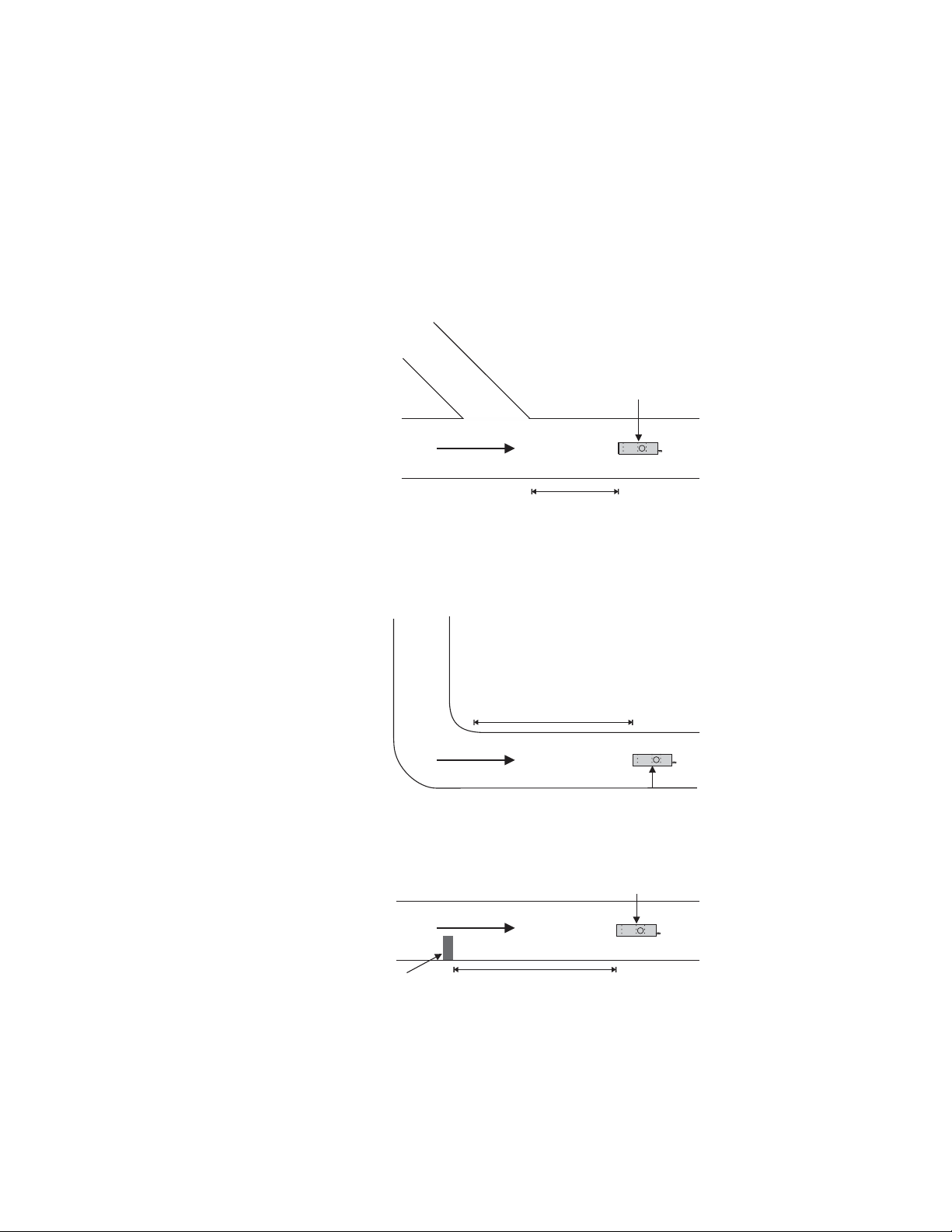
1. Flow Profile Distortion
The pipe/channel in which the QZ02 sensor is mounted should be free of bends, tees, sudden changes in
slope, and there should not be objects in the pipe/channel which disturb the flow profile in front of the
sensor.
In general, the QZ02 sensor should be mounted with at least 10 pipe diameters or channel widths of straight-
run upstream, and 5 pipe diameters or channel widths downstream:
QZ02
Top-Down
View
of
Channel
or
Pipe
FLOW
10 x
Pipe Diameter
or
Channel Width
Sensor
Top-Down
View
of
Channel
or
Pipe
Top-Down
View
of
Channel
or
Pipe
obstruction
in
flow stream
10 x Pipe Diameter
or
Channel Middle
FLOW
QZ02
Sensor
QZ02
Sensor
FLOW
10 x Pipe Diameter
or
Channel Width
25
Page 26
MANTARAY INSTRUCTION MANUAL
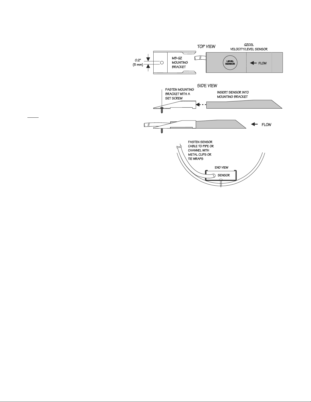
QZ02L VELOCITY-LEVEL SENSOR MOUNTING
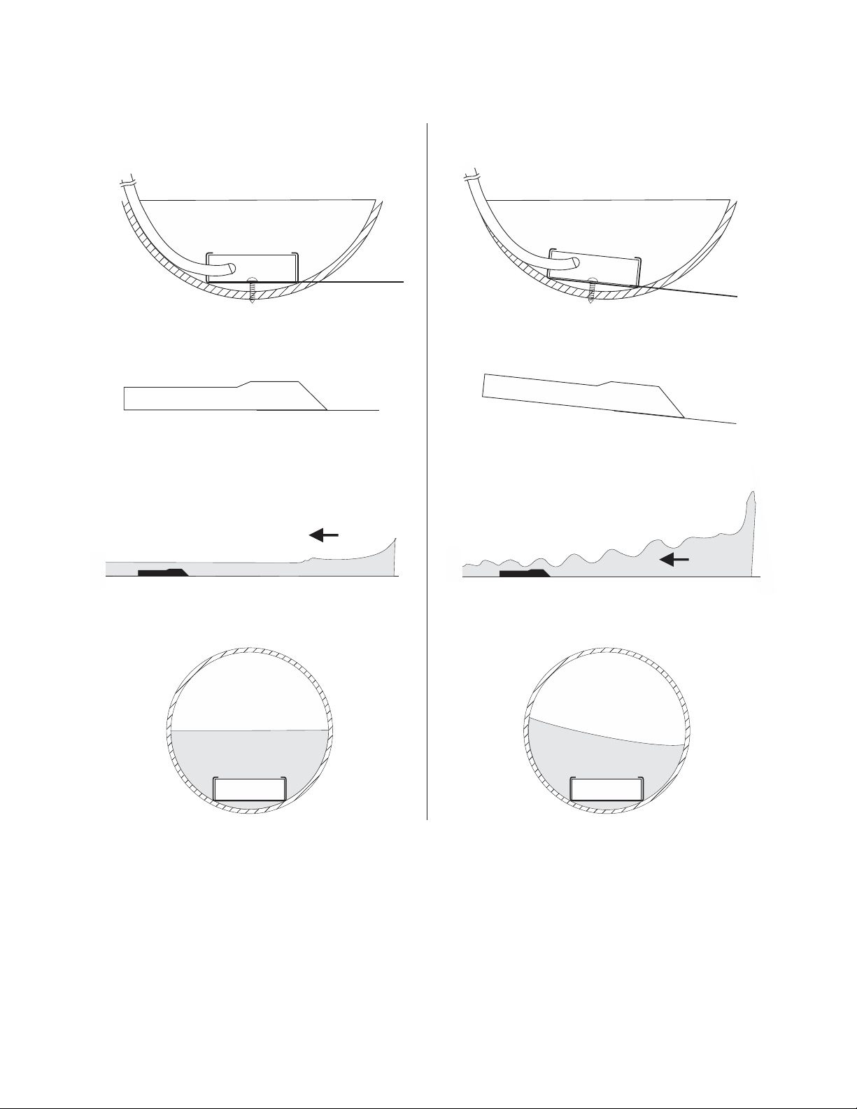
Mount the QZ02L sensor with the stainless
steel bracket and hardware supplied. Ensure
that the sensor is parallel to the water
surface (check with a level). Mount with the
tapered end of the sensor pointing
upstream and the sensor cable pointing
downstream.
Clip or tie wrap the sensor cable securely to
the pipe or channel wall.
Note: The mounting bracket is designed to
release the sensor if weeds or rags are
caught by the sensor.
26
Page 27
GOOD
BAD
END VIEW
SENSOR
PULSAR MEASUREMENT
E
N
D
V
I
E
W
S
E
N
S
O
R
SENSOR
SENSOR
SENSOR
END VIEW
FLOW
SENSOR
S
SENSOR
END VIEW
E
N
S
O
R
FLOW
27
Page 28
MANTARAY INSTRUCTION MANUAL
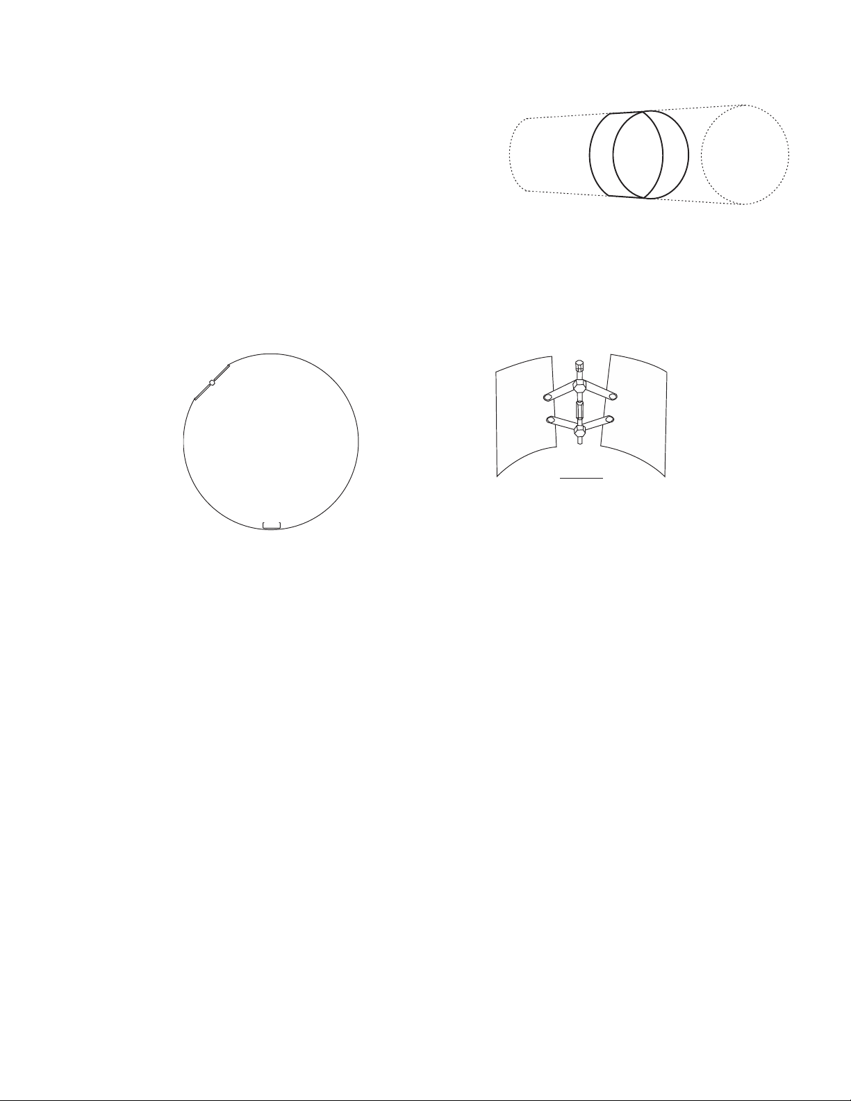
OPTIONAL VSJ PIPE BAND MOUNTING WITH QZ02L SENSOR
Install the stainless steel pipe band with the sensor mounting
bracket at the invert (bottom) of the pipe. Ensure that the sensor
bracket is parallel to the water surface (check with a level). Mount so
the tapered end of the sensor will point upstream and the sensor
cable will point downstream. (Turn the ¼” adjustment nut clockwise
to expand the bracket and secure to the pipe wall by friction fit.)
Note: VSJ6 and VSJ8 bands do not include adjustment jacks- they secure to pipe by spring tension.
Insert the sensor into the mounting bracket and tie-wrap the sensor cable securely to the pipe band using the
holes provided.
BAND
ADJUSTMENT JACK
VS J PIP E MOUN TING BAND
SENSOR MOUNTING
BRACKET
CLEANING
Cleaning is not required as a part of normal maintenance.
DETAIL
BAND ADJUSTMENT
JACK
28
Page 29
PULSAR MEASUREMENT
BREAK-OUT BOX
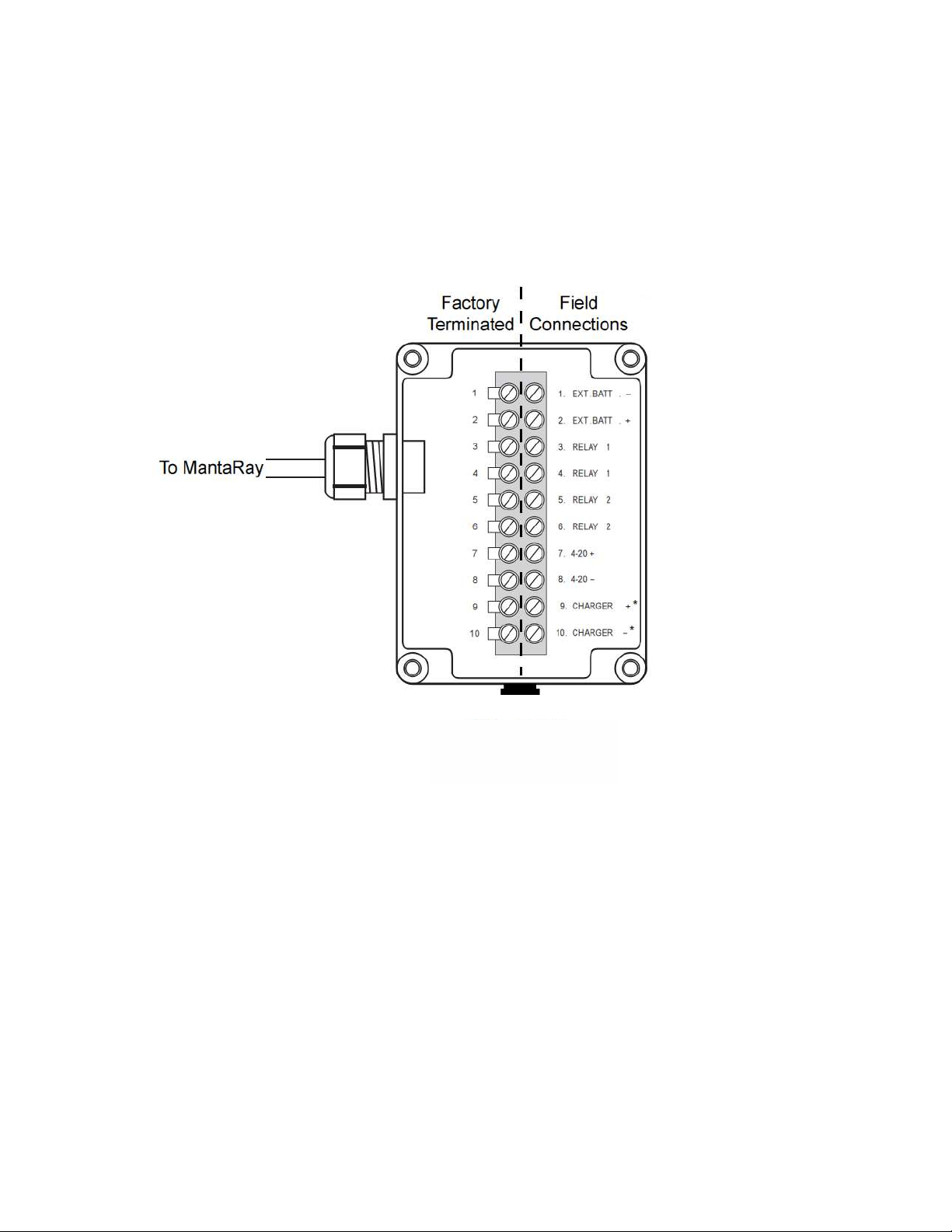
The break-out box provides connection for optional external battery, two relay outputs, a single 4-20mA/0-5V
output, and the barrel plug charger for the MantaRay. As shown in the diagram below, the left side of the
terminals come factory terminated with wires already on them, with connection back through the cable to the
MantaRay. The break-out box connects to the side of the MantaRay. Any user connections should be made on the
right-hand side of the break-out box, except the charger which should connect to the barrel plug on the outside
of the box.
Charger Connection
NEMA 4X / IP 66
DUST TIGHT / SPLASH PROOF
*Comes factory terminated
DIMENSIONS:
Width: 3.54” / 90 mm
Height: 4.72” / 120 mm
Depth: 2.42” / 61.5 mm
CABLE:
6 ft / 1.8 m with connection plug to MantaRay
EXTERNAL BATTERY CONNECTION:
10-30VDC; Efficiency best at 12 VDC 180 mA current draw at 12 VDC with no backlight or analog outputs
connected.
29
Page 30
MANTARAY INSTRUCTION MANUAL
SLEEP BUTTON AND TELEMETRY LOGGING INSTRUCTIONS
The Log Mode parameter in the Data Logging menu provides options of Sleep Btn and Telemetry. See the Data
Logging menu description earlier in this manual for instructions on how to set it.
SLEEP BUTTON
In the Data Logging menu, when a Log Mode of Sleep Btn is selected, and the Interval is 30s or greater, pressing
the “SLEEP” button on the front of the MantaRay will put the MantaRay in a low-power state by disabling the front
LCD display and other non-essential electronics. Then, based on the Interval, will automatically “wake-up” essential
electronics to make a measurement before going back to the low-power state. The approximate time for each
sleep measurement is 12 seconds. The LCD display will not turn on while in sleep mode. The analog output will
not activate during sleep button logging.
To bring the MantaRay out of sleep mode, press the “SLEEP” button on the front of the meter. If there is sufficient
battery life, the LCD display will turn back on and you can return to normal operation of the meter. If the battery
has completely drained, you will need to connect the external charger before using the MantaRay again.
IMPORTANT: Pressing the POWER button while the MantaRay is asleep will turn it off, stopping the logging. To
validate that the MantaRay went into sleep mode properly, press the “SLEEP” button to wake it up, then again to
put it back to sleep.
TELEMETRY LOGGING
In the Data Logging menu, when a Log Mode of Telemetry is selected, and the Interval is 30s or greater, pressing
the “SLEEP” button on the front of the MantaRay will put the MantaRay in a low-power state by disabling the front
LCD display and other non-essential electronics. Then, based on an external trigger described in more detail
below, will automatically “wake-up” essential electronics to make a measurement before going back to the lowpower state. The approximate time for each sleep measurement is 12 seconds. The LCD display will not turn on
while in sleep mode. The analog output will activate during telemetry logging to send a signal to the external
telemetry device.
Wiring Instructions: In order for the MantaRay to “wake-up”, make a measurement, and transmit the
measurement to an external logger or telemetry system, it requires a DC voltage to be applied to it through the
break-out box. The external DC voltage range is 10-18V. The duration the external voltage is applied should be at
least 12 seconds in order for the MantaRay to stabilize for an accurate measurement and transmit the signal. The
logger/telemetry system should log the 4-20mA output from the MantaRay at the end of the 12 second
measurement cycle.
Wiring instructions for connecting a generic external logger/telemetry system to the break-out box is as follows:
Break-out Box Terminal Marking External Logger/Telemetry Connection
Charger+ DC voltage trigger positive (9-18VDC)
Ext. Bat- DC voltage trigger negative
4-20mA+ 4-20mA input (MantaRay 4-20mA is internally powered)
4-20mA- 4-20mA ground
30
Page 31
PULSAR MEASUREMENT
TELEMETRY LOGGING (CONT.)
The telemetry logging feature of the MantaRay was validated to be compatible with the RANGER wireless
telemetry system from SignalFire. Follow these wiring and configuration instructions for proper operation.
Wiring:
Break-out Box Terminal Marking SignalFire RANGER Terminal
Charger+ A_PWR
Ext. Bat- GND (Terminal 3, between DIN2 and A_PWR)
4-20mA+ AIN
4-20mA- GND (Terminal 6, between AIN and COM)
RANGER configuration:
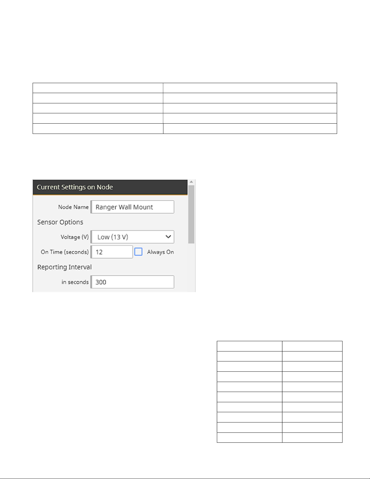
Ensure the RANGER is configured to provide 13V on the A_PWR terminal, and the “On Time” is 12 seconds. Both
of these options are available via the “Configure Node” button for the Ranger device in the SignalFire Cloud. See
picture below for reference:
The “Reporting Interval” can be set to any duration 30 seconds or longer (minimum interval may depend on
RANGER subscription service).
ESTIMATED BATTERY LIFE
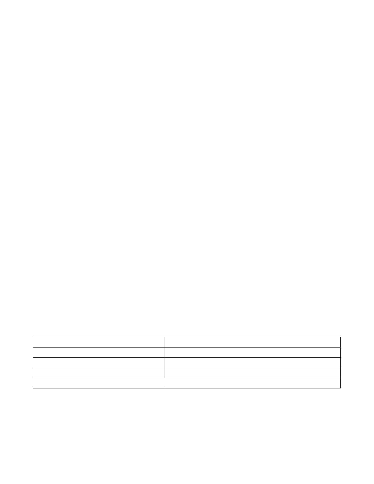
Use this table for estimated battery life at different Intervals. The
Intervals below are selected in the Data Logging menu of the
MantaRay, or set via the external telemetry logging system, as
shown above for the RANGER. Actual battery life may vary due to
environmental factors like temperature, as well as starting state of
charge and age of battery.
Interval Est. Battery Life
Continuous 40 hours
30s 6 days
1 min 10 days
2 min 18 days
5 min 38 days
10 min 52 days
15 min 74 days
30 min 90 days
60 min 110 days
31
Page 32

MANTARAY INSTRUCTION MANUAL
APPLICATIONS HOTLINE
For applications assistance, advice or information on any Pulsar Measurement Instrument contact your Sales
Representative, write to Pulsar Measurement or phone the Applications Hotline below:
COUNTRY
United
States
Canada 613-938-8956 613-938-4857
UK +44 (0) 1684 891371 +44 (0) 1684 575985 [email protected]
Asia
Oceania
TEL FAX E-MAIL ADDRESS
315-788-9500 315-764-0419
[email protected] 11451 Belcher Road South
Largo, FL 33773
[email protected] 16456 Sixsmith Drive
Long Sault, Ont. K0C 1P0
Cardinal Building
Enigma Commercial Centre
Sandy's Road, Malvern
WR14 1JJ
34-1A, Jalan 10A/KU5
Taman Aman Perdana
41050 Klang, Selangor, Malaysia
N/A
PRODUCT RETURN PROCEDURE
Instruments may be returned to Pulsar Measurement for service or warranty repair.
1 Obtain an RMA Number from Pulsar Measurement Before shipping a product to the factory please contact Pulsar Measurement by telephone, fax or email to obtain
an RMA number (Returned Merchandise Authorization). This ensures fast service and correct billing or credit.
When you contact Pulsar Measurement please have the following information available:
1. Model number / Software Version
2. Serial number
3. Date of Purchase
4. Reason for return (description of fault or modification required)
5. Your name, company name, address and phone number
2 Clean the Sensor/Product -
Important: unclean products will not be serviced and will be returned to the sender at their expense.
1. Rinse sensor and cable to remove debris.
2. If sensor has been exposed to sewage, immerse both sensor and cable in a solution of 1 part household bleach
(Javex, Clorox etc.) to 20 parts water for 5 minutes. Important: do not immerse open end of sensor cable.
3. Dry with paper towels and pack sensor and cable in a sealed plastic bag.
4. Wipe the outside of the enclosure to remove dirt or deposits.
5. Return to Pulsar Measurement for service.
32
Page 33

_____________________________________
Pulsar Measurement warrants, to the original purchaser, its products to be
free from defects in material and workmanship for a period of two years
from date of invoice. Pulsar Measurement will replace or repair, free of
charge, any Pulsar product if it has been proven to be defective within the
warranty period. This warranty does not cover any expenses incurred in the
removal and re-installation of the product.
If a product manufactured by Pulsar should prove defective within the first
year, return it freight prepaid to Pulsar Measurement along with a copy of
your invoice.
This warranty does not cover damages due to improper installation or
handling, acts of nature, or unauthorized service. Modifications to or
tampering with any part shall void this warranty. This warranty does not
cover any equipment used in connection with the product or consequential
damages due to a defect in the product.
All implied warranties are limited to the duration of this warranty. This is
the complete warranty by Pulsar Measurement and no other warranty is
valid against Pulsar Measurement. Some states do not allow limitations on
how long an implied warranty lasts or limitation of incidental or
consequential damages, so the above limitations or exclusions may not
apply to you.
This warranty gives you specific legal rights, and you may also have other
rights which vary from state to state.
Pulsar Measurement
PULSAR MEASUREMENT
LIMITED WARRANTY
33
Page 34
MANTARAY INSTRUCTION MANUAL
SPECIFICATIONS
Electronics
Channel Types: Round pipe, rectangular, trapezoid, egg or custom shapes
Electronics Enclosure: Polycarbonate, IP67 while plugs connected or covered
Operating Temp. (Electronics): -5° to 140°F (-20° to 60°C)
Accuracy: Level: ±0.25% of reading or ±0.08in (±2.03mm), whichever is greater
Velocity: ±2% of reading or ±0.04ft/s (±0.012m/s), whichever is greater.
Requires solids or bubbles minimum size of 100 microns, minimum
concentration 75 ppm.
Repeatability and Linearity 0.5%
Display: White, backlit matrix - displays flow rate, totalizer, relay states, operating
mode and calibration menu
Programming: Built-in 5-button keypad with English, French or Spanish language
selection
Battery: Internal rechargeable NiMH, 12V, 10,000 mAh
Power Adapter: 16.5V, 4.2A (69.3W Max), 100-240VAC 50/60Hz input, 2.0A,
UL and CE listed
Outputs/Communications: 4-20mA or 0-5VDC (100 mA) by menu selection. 500Ω max impedance.
2 solid-state Relays, 32V AC/DC max., rated 400mA;
Break-out Box: Connections for charger input, external battery input, 2 relays, 4-20mA
(0-5V), and external telemetry logger
Data Logger (internal): Programmable 26-million point capacity, time and date stamped plus
formatted flow reports including Total, Average, Minimum, Maximum
and times of occurrence.
Data Logger Intervals: Programmable 10s, 30s, 1min, 2min, 5min, 10min, 15min, 30min, 60min
Software: Greyline Logger for Windows. Graph and data table presentation,
level/velocity to flow conversion, exports data to Excel™, exports graphs
Approximate Shipping Weight: 15 lbs. (6.8 kg)
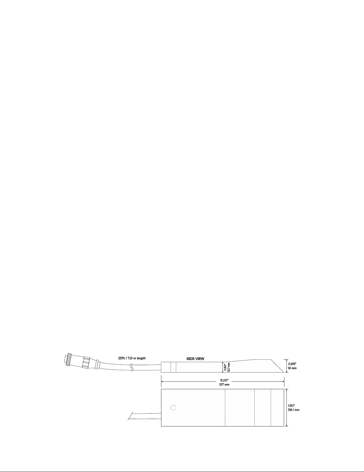
Velocity/Level Sensor QZ02L
Velocity Measurement Range: 0.1 to 20 ft/sec (0.03 to 6.2 m/sec) and reverse flow to -5ft/s (-1.5 m/s)
Level Measurement Range: Minimum Head: 1in (25.4 mm). Maximum Head: 15ft (4.6m)
Operating Temperature: 5 to 175°F (-15 to 80°C)
Exposed Materials: 316 stainless steel, epoxy resin, polyurethane
Sensor Cable: 25ft (7.6 m) submersible polyurethane jacket, shielded, 3 coaxial
Sensor Mounting: includes MB-QZ stainless steel mounting bracket
Temperature Compensation: Automatic, continuous
34
Page 35

PULSAR MEASUREMENT
35
Page 36

MANTARAY INSTRUCTION MANUAL
www.pulsarmeasurement.com
Copyright © 2020 Pulsar Measurement Ltd..
Registered Address: 1 Chamberlain Square CS, Birmingham B3 3AX
Registered No.: 3345604 England & Wales
Rev 3.1
36
 Loading...