

Greyline ISM 5.0 User Manual

www.greyline.com
USER'S GUIDE
Installation & Operation
Instructions
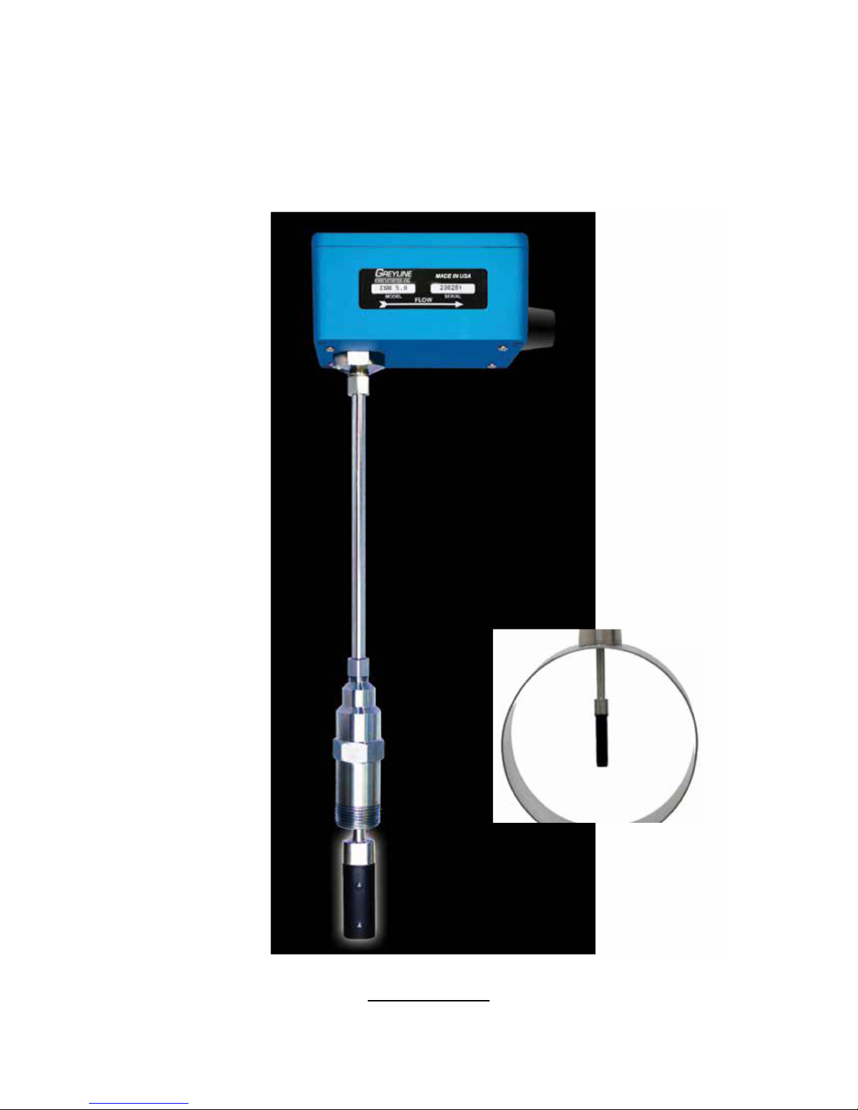
Insertion Magmeter
Model ISM 5.0
Manual Series 1.2

Note: This page has been left blank intentionally.
ISM 5.0 INSERTION MAGMETER
Installation and Operation Guide
www.greyline.com
Page 2
SAFETY INFORMATION
Messages identified as “Caution” contain information regarding potential damage to the
product or other ancillary products.
Messages identified as “Important Note” contain information critical to the proper operation of
the product.
Messages identified as “Warning” contain information regarding the personal safety of
individuals involved in the installation, operation or service of this product.
! i !
This meter was calibrated at the factory before shipment. To ensure correct use of the meter, please read
this manual thoroughly.
Regarding this Manual:
•
This manual should be passed on to the end user.
•
Before use, read this manual thoroughly to comprehend its contents.
•
The contents of this manual may be changed without prior notice.
•
All rights reserved. No part of this manual may be reproduced in any form without
GREYLINE’s written permission.
•
GREYLINE makes no warranty of any kind with regard to this material, including, but
not limited to, implied warranties of merchantability and suitability for a particular
purpose.
•
All reasonable effort has been made to ensure the accuracy of the contents of this manual.
However, if any errors are found, please inform GREYLINE.
•
GREYLINE assumes no responsibilities for this product except as stated in the warranty.
•
If the customer or any third party is harmed by the use of this product, GREYLINE
assumes no responsibility for any such harm owing to any defects in the product which
were not predictable, or for any indirect damages.
Safety Precautions:
The following general safety precautions must be observed during all phases of installation,
operation, service, and repair of this product. Failure to comply with these precautions or with
specific WARNINGS given elsewhere in this manual violates safety standards of design,
manufacture, and intended use of the product. GREYLINE Instruments assumes no liability for the
customer’s failure to comply with these requirements. If this product is used in a manner not
specified in this manual, the protection provided by this product may be impaired.
The following symbols are used in this manual:
WARNING
CAUTION
IMPORTANT NOTE

Page 3
1.1
2.1
3.1
TABLE OF CONTENTS
INTRODUCTION ........................................................................................................................................................ 4
1.2
PURPOSE OF THIS GUIDE ..................................................................................................................... 4
1.3
TYPICAL INSERTION ELECTROMAGNETIC FLOW METER .................................................... 4
1.4
STANDARD FEATURES AND SPECIFICATIONS ......................................................................... 5
1.5
ADDITIONAL REQUIRED HARDWARE ................................................................................................. 5
1.6
ADDITIONAL HARDWARE THAT MAY BE REQUIRED .......................................................... 6
1.5.1 Grounding Rings ................................................................................................................................... 6
UNPACKING ......................................................................................................................................................................... 7
2.2
CHECKING THAT YOU HAVE RECEIVED EVERYTHING .............................................................. 7
INSTALLATION, REMOVAL & ADJUSTMENT ................................................................................................. 8
3.2
INSTALLATION SITE SELECTION .................................................................................................... 8
3.3
MECHANICAL INSTALLATION ................................................................................................................... 10
3.3.1
Installation Kit ................................................................................................................................... 11
3.3.2
GREYLINE Standard Installation Hardware Kit ................................................................. 11
4.1
3.3.3
GREYLINE Hot Tap Installation Hardware Kit ................................................................... 11
3.3.4
Customer Supplied Installation Hardware ........................................................................... 12
3.3.5
Confirming the Stack Height ....................................................................................................... 13
3.3.6
Installing Grounding Rings .......................................................................................................... 14
3.3.7
Installing the Flow Meter ............................................................................................................. 15
3.4
INSERTION OF THE METER .............................................................................................................. 16
3.4.1
Inserting the Flow Meter ............................................................................................................... 16
REMOVAL OF THE
3.5
WIRING CONNECTIONS ...................................................................................................................... 18
3.5.1
3.5.2
START-UP & COMMISSIONIING FOR GREYLINE INSERTION ELECTROMAGNETIC FLOW
METERS..................................................................................................................................................................... 21
4.2
HELPFUL HINTS FOR START-UP AND COMMISSIONING ................................................. 21
4.3
START-UP AND COMMISSIONING ................................................................................................ 22
4.4
START-UP AND COMMISSIONING WORKSHEET .................................................................. 23
METER……………………………………………………………………………………………………… 17
Signal and Power Wiring Connections ................................................................................... 18
Earth Connection ............................................................................................................................. 20
4.5
TROUBLESHOOTING GUIDE ............................................................................................................. 24
4.4.1 Earth Connections & Electrical Noise Reduction ................................................................. 24
APPENDIX
Conditions of Sale …………………………………………………………………………………………………………………26
Applications Hotline ……………………………………………………………………………………………………………..27
Product Return Procedure …………………………………………………………………………………………………….27
Page 4
water and steam systems, according to their individual trades. Death or permanent injury may
result from accidents with these systems.
!
SECTION 1.0: INTRODUCTION
We, at GREYLINE Instruments, would like to thank you for purchasing our quality American made
ISM 5.0 Insertion Magmeter. As our valued customer, our commitment to you is to provide
reliable service, while continuing to offer you quality products to meet your growing flow
measurement needs.
1.1 PURPOSE OF THIS GUIDE
fast
We have written this guide to provide the persons responsible for the installation, operation and
maintenance of your flow meter with the most specific equipment information they will need.
This is NOT an electrical or plumbing trade manual.
WARNING
Please do not permit persons to install, operate or maintain this equipment unless they have a
This guide is the basic reference tool for all GREYLINE ISM 5.0 Insertion Magmeters. If you have
not purchased all of the options, there will be references in this manual which are not applicable
to your meter(s).
1.2 TYPICAL INSERTION ELECTROMAGNETIC FLOW METER
Faraday’s Law of electromagnetic induction states that a voltage will be induced in a conductor
when it passes through a magnetic field, and the induced voltage will be directly proportional to
the velocity of the conductor.
GREYLINE ISM 5.0 Insertion Magmeters generate pulsating magnetic fields that are used to induce
a voltage into the conductive fluid flowing through the pipe. Electrodes located on the flow meter
sensor head measure the induced voltage. Circuitry within the flow meter electronics
then converts the voltage to digital and analog signals that convey flow rate and total data via
connecting the cable to any of GREYLINE’s display devices, Btu meters and/or to a data
acquisition system.
complete knowledge of their trade skills and are competent to work on high pressure hot and cold
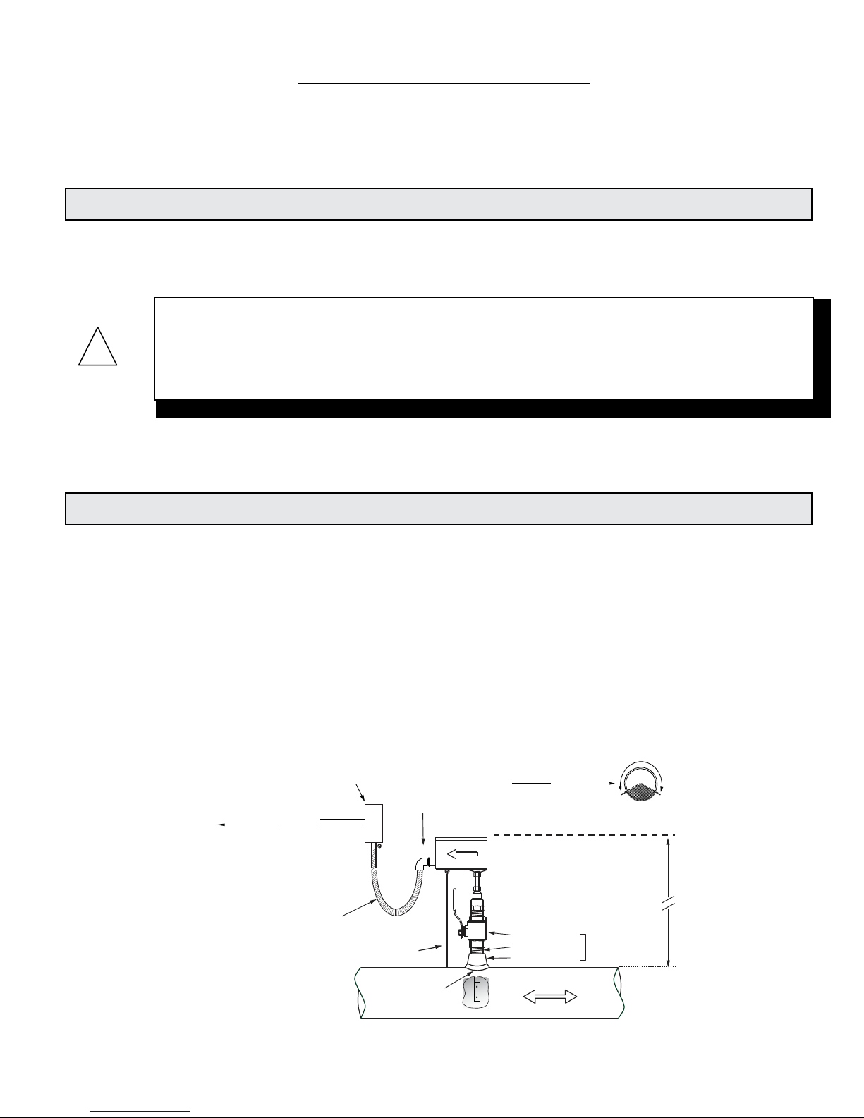
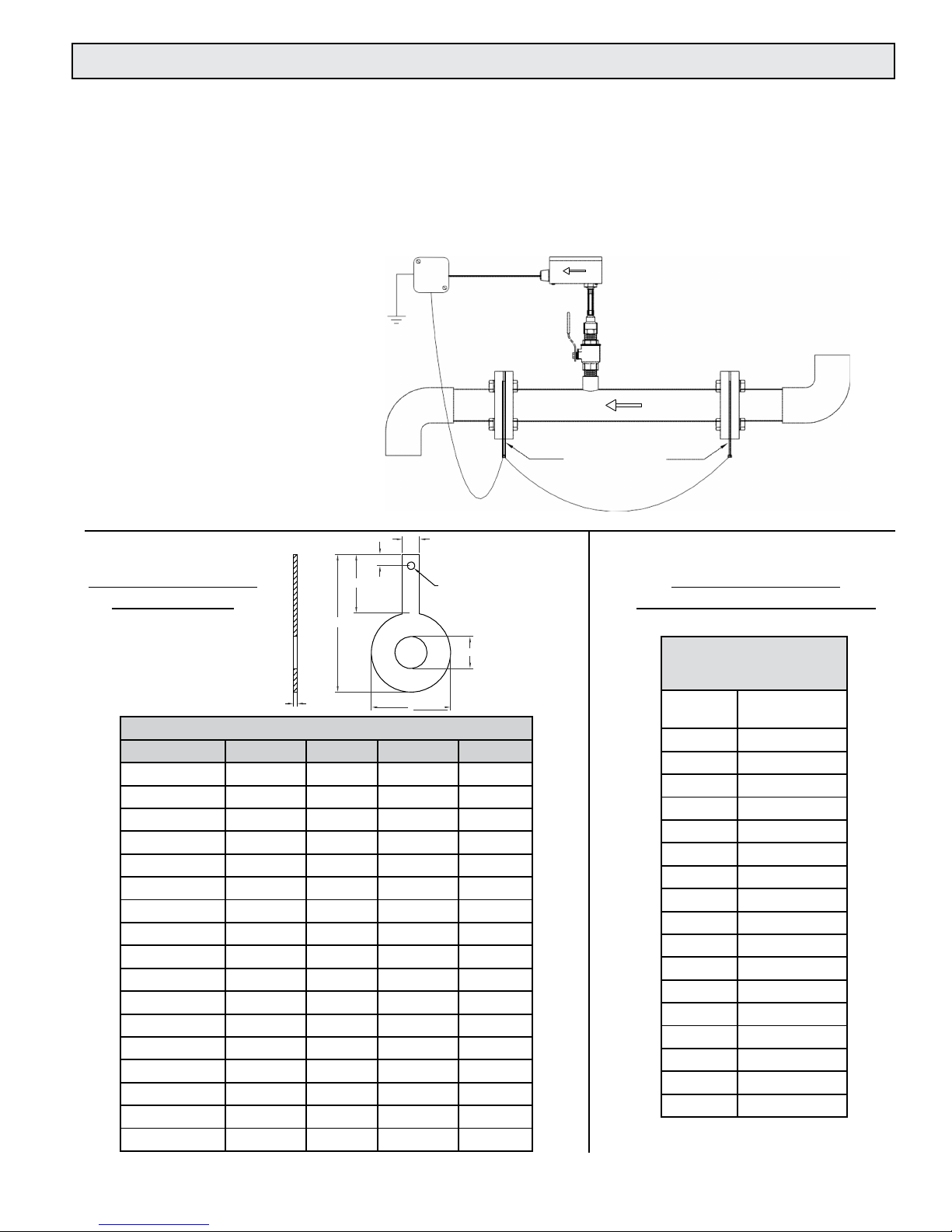
Typical Meter Installation
(New construction or scheduled shutdown)
Output sign al(s)
to control
system
Greyline
Displa y or
BTU Meter
(Optional )
Allow enough slack
in the flexibl e liquidtight conduit to
permit th e meter to
be remov ed
from the val ve.
Custom er provided
conduit and adapters
Note: Installati on kits vary based on pipe material and application. For install ations in pressurized (live)
systems, use "Hot tap" 1¼ inch installation kit and drill hole using a 1 inch wet tap drill.
½" FNPT
conduit connection
Insertion depth
gage provided
with ea ch meter
Minim um Hole Size = 1"
Must be centered
•
Install in vertical or horizontal pipe
•
For horizontal pipe position meter
anywhere in upper 240˚
Standard Installatio n
Kit for Steel Pipe
1" Full port bal l valve
1" Close nippl e
1" Branch outl et
FLOW
FOR INSTALLATION
1¼" for
hot tap
CLEARANCE
REQUIRED
Typically
30" - 40"
dependi ng on
pipe size and
height of v alve
assembly.
enclosure
Page 5
1.3 STANDARD FEATURES AND SPECIFICATIONS
Accuracy
Sensing Method
Pipe Size Range
± 1.0% of reading from 2 to 20 ft/sec
± 0.02 ft/sec below 2 ft/sec
Electromagnetic, no moving parts
3” through 72” nominal
Input Power
20 - 28 VAC 50/60Hz, 250 mA maximum
20 - 28 VDC, 250 mA maximum
Liquid Temperature Range
15° to 250° F
Ambient Temperature Range
-5° to 150° F
Operating Pressure
400 PSI maximum
Pressure Drop
Less than 0.1 psi at 12 ft/s velocity in 3” and larger pipes
Materials of Construction
Wetted metal components - 316L stainless steel
Sensor head - Polystyrene
Electronics enclosure - Powder coat painted cast aluminum
Enclosure Rating
Watertight, airtight, dust proof powder coated cast aluminum.
Electrical Connections
25’ of PVC jacketed cable with ½” NPT conduit connection
Output Signal(s)
Analog output (Isolated), selectable 4-20 mA, 0-10 V or 0-5 V
Frequency output, 0-15 V peak pulse, 0-500 Hz maximum
Scalable pulse output, isolated dry contact, contact rating 50 VDC @ 100 mA
maximum, pulse duration: 0.5, 1, 2 or 6 seconds
This product is covered by one or more of the following patents: 6,431,011 and 6,463,807.
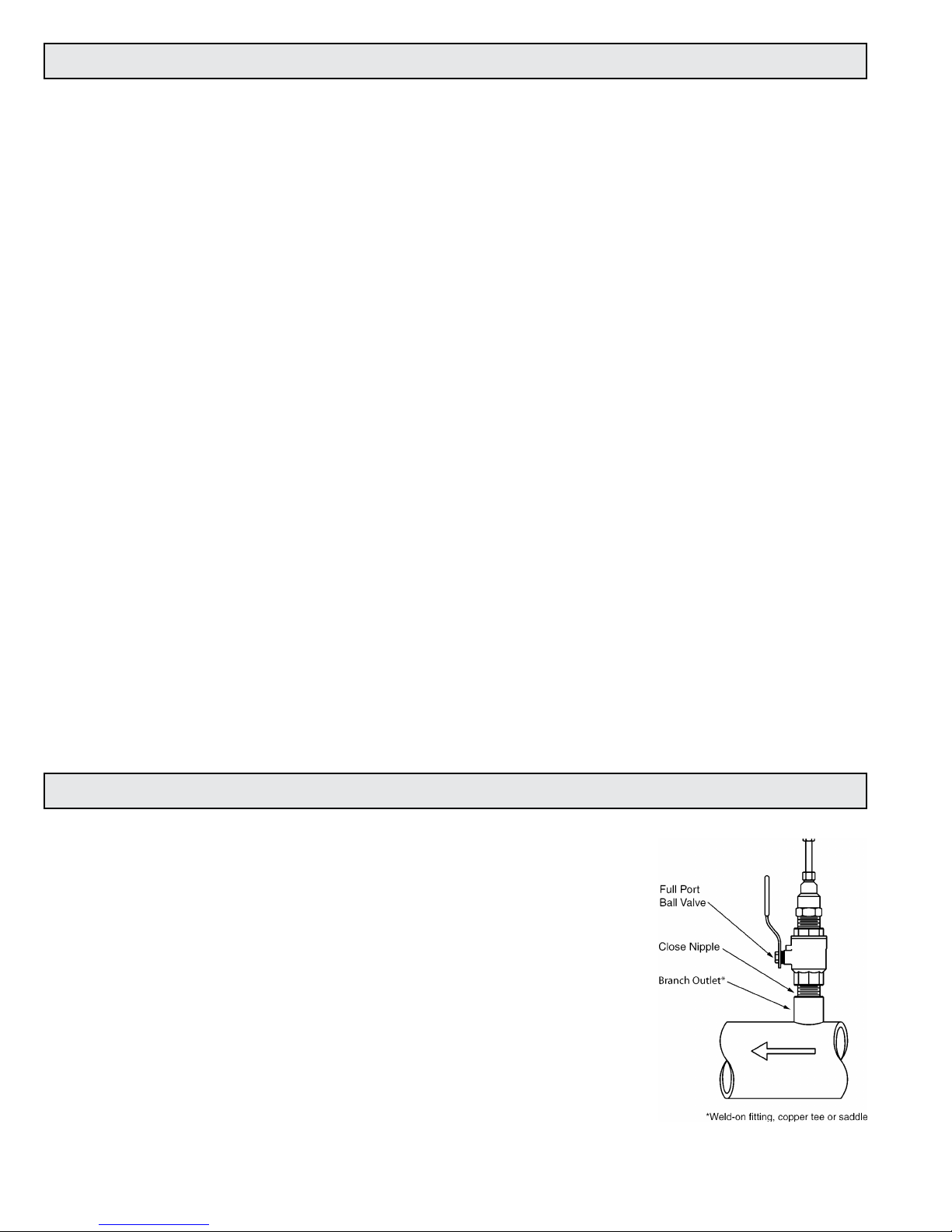
1.4
ADDITIONAL REQUIRED HARDWARE
All GREYLINE insertion type meters can be installed and removed via
a 1” or larger full port ball valve without system shutdown. The terms
“Standard” and “Hot Tap” refer to the installation method of the
isolation valve kit only.
Standard Installation Hardware: For new construction or scheduled
shutdown; once kit is installed, the flow meter can be installed
or removed without system shutdown.
Hot Tap Installation Hardware: For applications which require the
access hole in the pipe to be drilled through the valve using a
wet tap drilling machine while the hydronic system is
pressurized and operating.
NOTE: Installation hardware materials vary greatly based on pipe
material, pipe size and standard vs. hot tap versions.
Page 6
5/8
3/8
GROUNDING RING
DIMENSIONS
D
1/4
GROUNDING RING
ORDERING INFORMATION
C
Bore
1/8”
A
ANSI Class 150
316 Stainless Steel
Grounding Rings (pair)
Nominal
Size
GREYLINE
Part 1” 19265
1½” 19266
2” 19267
3” 19268
4” 19269
6” 19270
8” 19271
10” 19272
12” 19273
14” 19274
16” 19275
18” 19276
20” 19277
24” 19278
30” 19279
36” 19280
42” 19281
Grounding Rings
Grounding Ring Dimensions
Nominal Size
Bore A C D
1”
1 - 1/16
2 - 5/8
4 - 9/16
1 - 15/16
1.5”
1 – 9/16
3 – 3/8
5 - 5/16
1 - 15/16
2”
2 – 1/16
4 – 1/8
6 - 1/16
1 - 15/16
3”
3 – 1/16
5 – 3/8
7 - 5/16
1 - 15/16
4”
4 – 1/16
6 – 7/8
8 - 13/16
1 - 15/16
6” 6
8 – 3/4
10 - 11/16
1 - 15/16
8” 8
11
12 - 15/16
1 - 15/16
10”
9 – 1/2
13 – 3/8
15 - 5/8
2 - 1/4
12”
11 – 9/16
16 – 1/8
18 - 9/16
2 - 7/16
14”
13 – 1/2
17 – 3/4
20 - 3/8
2 - 5/8
16”
15 – 1/4
20 – 1/4
22 - 7/8
2 - 5/8
18”
17 – 3/8
21 – 5/8
24 - 1/4
2 - 5/8
20” 19
23 - 7/8
26 - 11/16
2 - 13/16
24” 23
28 – 1/4
31 - 1/8
2 - 7/8
30” 29
34 – 3/4
38
3 - 1/2
36” 35
41 – 1/4
45 - 1/4
4
42” 41
48
52 - 1/2
4 - 1/2
1.5 ADDITIONAL HARDWARE THAT MAY BE REQUIRED
1.5.1 Grounding Rings
Grounding rings may be required whenever meters are installed in non-metallic or lined pipes.
Grounding rings placed before and after the meter eliminate electrical noise that will interfere
with the proper operation of the meter. GREYLINE provides grounding rings as an optional
accessory. Grounding ring dimensional information and part numbers are listed below. For proper
operation, grounding rings are required before and after the meter.
Typical Installation
Non-conductive Pipe

Page 7
SECTION 2.0: UNPACKING
GREYLINE insertion magnetic flow meters are packed and shipped in individual cartons. An optional
installation hardware kit INSTL 1 or INSTL 2, if ordered, will be packaged with each meter. All other
installation hardware and peripheral devices, including Btu meters and display modules, will be
packaged and shipped separately.
Please open all packages with care to prevent damage to their contents. Carefully inspect each item for
signs of damage in transit. The flow meter stem should be straight and free of blemishes or abrasions.
The sensor head should have a smooth continuous surface that is free of abrasions.
All GREYLINE products are shipped insured unless the customer specifically requests otherwise.
Please notify the shipping company and GREYLINE immediately if any items are damaged in transit.
Save all
2.1
packing material for inspection by the shipper.
CHECKING THAT YOU HAVE RECEIVED EVERYTHING
Standard Documentation
Enclosed with each meter is a comprehensive documentation package that includes the
following items:
Installation and Operation Guide
Flow Meter Certificate of Calibration
Please notify GREYLINE if any of these documents are missing.
ISM 5.0 Insertion Magmeter Flow Meters
Optional INSTL1 or INSTL2 Installation Hardware Kit, if ordered
 Loading...