

Page 1
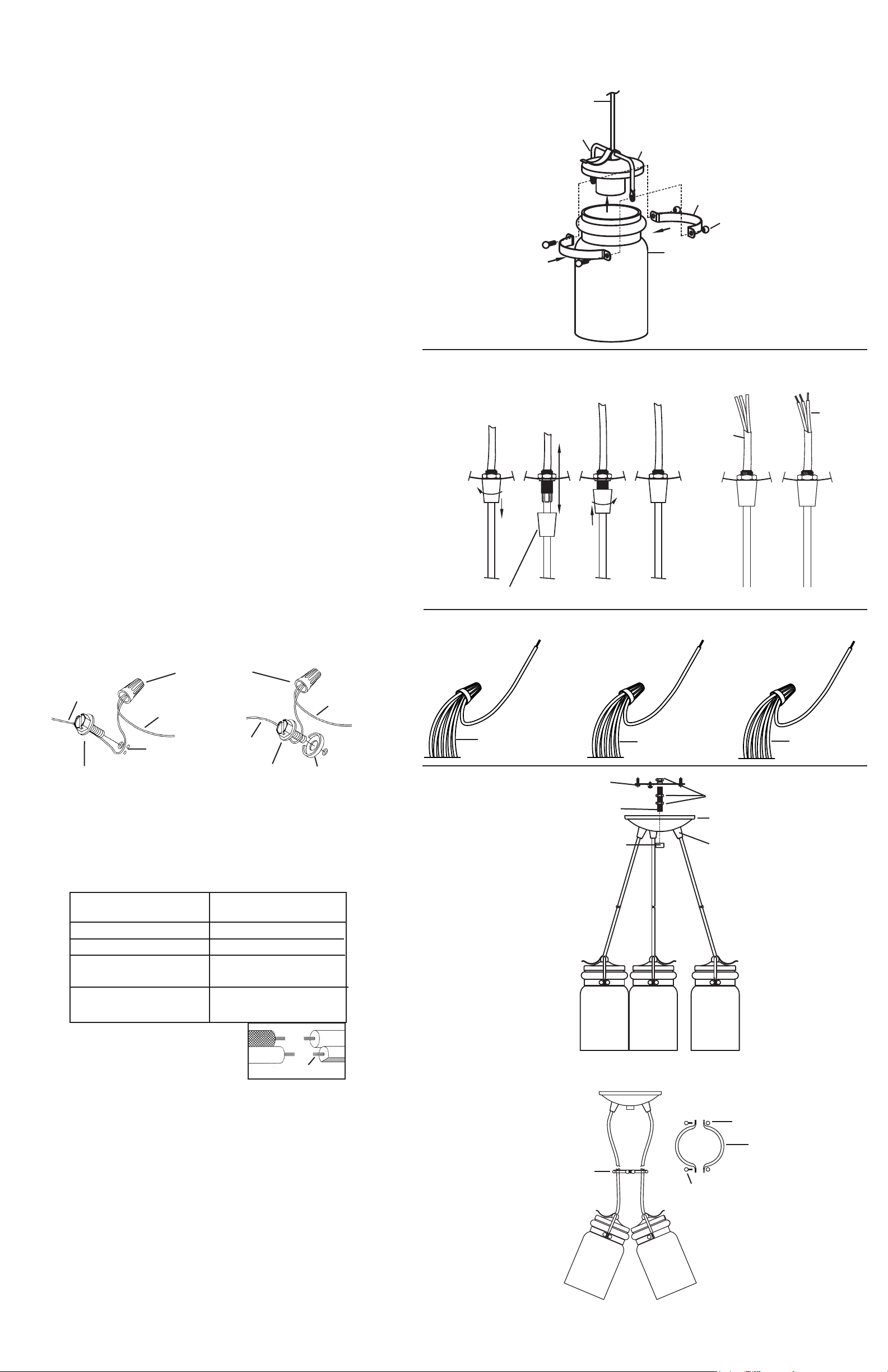
1) Insert recommended bulbs.
2) Lower cap down to glass. Fit bulb inside glass.
3) Fit one bracket around indentation in glass. Align holes on each end of bracket
with holes at end of each arm on fixture.
4) Fit second bracket around indentation in glass. Align hole on each end of bracket
with holes at end of each arm on fixture and holes in first bracket.
5) Slip end of one ball stud through holes in brackets and arm.
6) Thread ball knob onto end of ball stud protruding from hole in bracket.
7) Repeats steps 5 and 6 for remaining ball stud and ball knob.
8) Tighten both ball knobs to secure brackets in place.
9) Adjust the length of the cords to achieve the desired height of the mounted
fixture. REF: Strain Relief Removal for Cord Adjustment drawing.
To adjust cord length: On outside of canopy on each cord is a strain relief.
Unscrew strain relief from plastic threaded pipe on canopy and slide strain relief
down cord a few inches. Pull cord up or down to lengthen or shorten cord. Once
desired height of fixture is achieved, raise the strain relief on the outside of
canopy up the cord and thread strain relief onto plastic threaded pipe. Tighten
strain relief until top of strain relief is flush with canopy.
10) TURN OFF POWER.
IMPORTANT: Before you start, NEVER attempt any work without shutting off the
electricity until the work is done.
a) Go to the main fuse, or circuit breaker, box in your home. Place the main
power switch in the “OFF” position.
b) Unscrew the fuse(s), or switch “OFF” the circuit breaker switch(s), that control
the power to the fixture or room that you are working on.
c) Place the wall switch in the “OFF” position. If the fixture
to be replaced has a switch or pull chain, place those in the “OFF” position.
11) Trim wire jacket with fixture wires short enough so after all connections are made
wires will fit inside canopy. Make sure enough wire remains to easily make wire
connections.
12) With wire strippers, remove 2 inches from end of each wire jacket. Then strip 1/2 inch
from end of each colored wire from wire jacket. REF: Stripped wires detail.
13) Thread hexnut onto threaded pipe so that approximately 5 threads are exposed
above hexnut. Thread that end of threaded pipe into mounting strap. Thread
second hexnut onto end of threaded pipe protruding from back of mounting
strap. Tighten both hexnuts against mounting strap
14) Attach mounting strap to outlet box. (Screws not provided)
15) Grounding instructions: (See Illus. A or B).
A) On fixtures where mounting strap is provided with a hole and two raised
dimples. Wrap ground wire from outlet box around green ground screw, and
thread into hole.
B) On fixtures where a cupped washer is provided. Attach ground wire from
outlet box under cupped washer and green ground screw, and thread into
mounting strap.
If fixture is provided with ground wire. Connect fixture ground wire to outlet box
ground wire with wire connector. (Not provided.) After following the above steps.
Never connect ground wire to black or white power supply wires.
A
OUTLET BOX
GROUND
GREEN GROUND
SCREW
WIRE CONNECTOR
(NOT PROVIDED)
FIXTURE
GROUND
DIMPLES
OUTLET BOX
GROUND
GREEN GROUND
SCREW
B
FIXTURE
GROUND
CUPPED
WASHER
16) Connect each black wire together with one black jumper wire with wire connector.
REF: Fixture wiring detail.
17) Connect each green wire together with one green jumper wire with wire connector.
REF: Fixture wiring detail.
18) Connect each white wire together with one white jumper wire with wire connector.
REF: Fixture wiring detail.
19) Make wire connections (connectors not provided.) Reference chart below for
correct connections and wire accordingly.
Connect Black or
Red Supply Wire to:
Connect
White Supply Wire to:
Black White
*Parallel cord (round & smooth) *Parallel cord (square & ridged)
Clear, Brown, Gold or Black
without tracer
Insulated wire (other than green)
with copper conductor
Clear, Brown, Gold or Black
with tracer
Insulated wire (other than green)
with silver conductor
CORD
CORDÓN
ARM
BRAZO
BALL STUD
PERNO ESFÉRICO
CAP
TAPA
STRAIN RELIEF REMOVAL FOR CORD ADJUSTMENT
REMOCIÓN DEL ALIVIO DE LA TENSIÓN PARA EL
AJUSTE DEL CORDÓN
STRAIN RELIEF
ALIVIO DE LA TENSIÓN
FIXTURE WIRING DETAIL
DETALLE DEL ALAMBRADO DEL ARTEFACTO
BLACK JUMPER WIRE
ALAMBRE DE CONEXIÓN
NEGRO
BLACK WIRES
ALAMBRES NEGROS
MOUNTING STRAP
PLANCHA PARA MONTAR
THREADED PIPE
TUBO ROSCADO
GREEN JUMPER WIRE
ALAMBRE DE CONEXIÓN
VERDE
GREEN WIRES
ALAMBRES VERDES
FINIAL
CAPUCHÓN
BRACKET
MÉNSULA
PERILLA ESFÉRICA
GLASS
VIDRIO
STRIPPED WIRES DETAIL
WIRE JACKET
CAMISA DE
ALAMBRE
TUERCA HEXAGONAL
FIXTURE
ARTEFACTO
STRAIN RELIEF
ALIVIO DE LA TENSIÓN
BALL KNOB
DETALLE DE LOS
ALAMBRES PELADOS
COLORED
WIRES
ALAMBRE
DE COLOR
WHTIE JUMPER WIRE
ALAMBRE DE CONEXIÓN
BLANCO
WHITE WIRES
ALAMBRES BLANCOS
HEXNUT
*Note: When parallel wires (SPT I & SPT II)
are used. The neutral wire is square shaped
or ridged and the other wire will be round in
shape or smooth (see illus.)
Neutral Wire
20) Push fixture to ceiling, carefully passing threaded pipe through hole in canopy.
CAUTION: Be careful not to pinch wires between canopy and ceiling.
21) Thread finial onto threaded pipe. Tighten finial to secure fixture to ceiling.
To Attach Optional Slide Ring:
1) Gather cords together.
2) Place one half of slide ring around cords so cords fit inside curve of slide ring half.
3) Place other half of slide ring around cords on the opposite side of first slide ring
half. Fit cords inside curve of slide ring.
4) Align holes in ends of each half of slide ring.
5) Pass end of one ball stud through one hole in ends of one side of each slide ring.
6) Thread ball knob onto end of ball stud protruding through hole in slide ring.
7) Repeat steps 5 and 6 to attach other side of slide ring.
8) Tighten both ball knobs to secure two halves of slide ring together.
OPTIONAL SLIDE RING
ANILLO DESLIZANTE OPCIONAL
BALL KNOB
PERILLA REDONDA
SLIDE RING
ANILLO DESLIZANTE
SLIDE RING
ANILLO DESLIZANTE
BALL STUD
ESPÁRRAGO DE
CABEZA ESFÉRICA
SEE OTHER SIDE FOR SPANISH TRANSLATIONS.
VEA EL OTRO LADO DE TRADUCCIONES AL ESPAÑOL.
Page 2
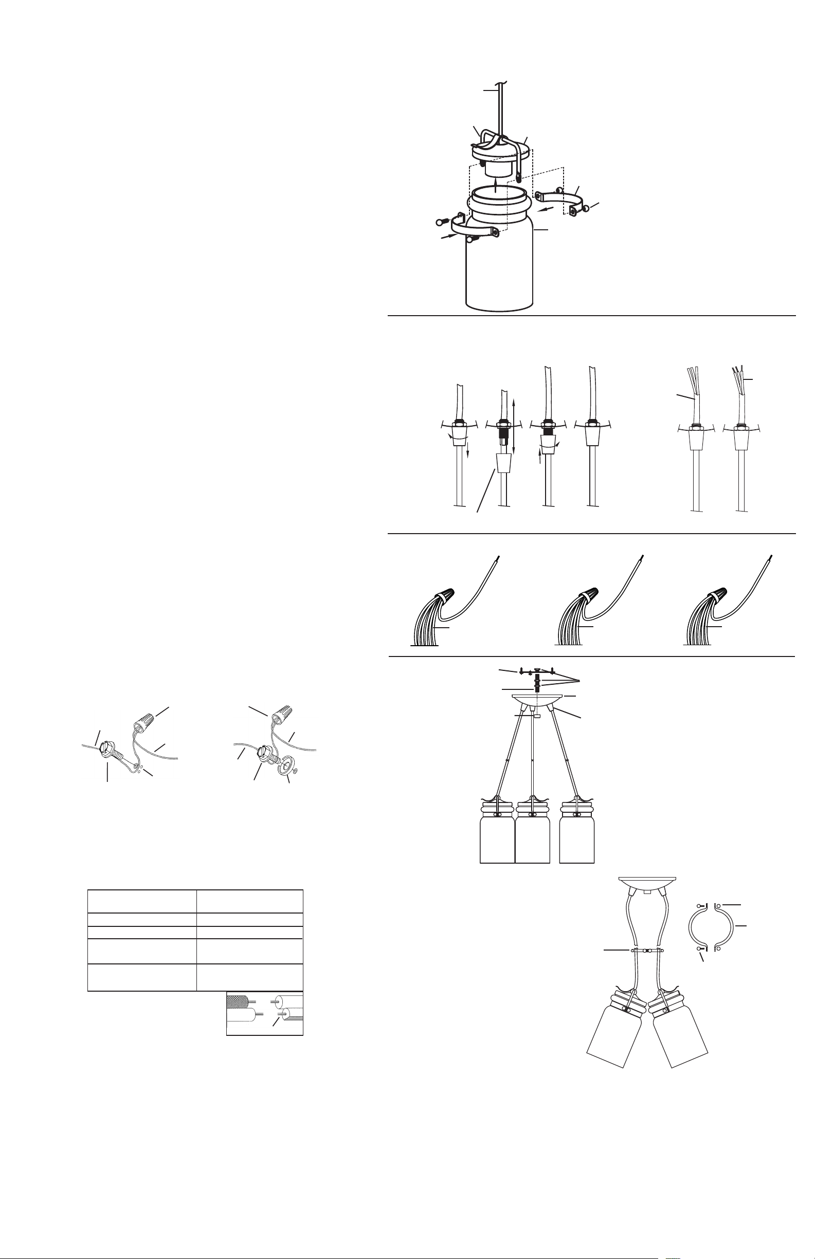
1) Inserte la bombilla que se recomienda.
A
2) Haga descender la tapa hasta el vidrio. Acomode la bombilla dentro del vidrio.
3) Ajuste una ménsula alrededor de la indentación en el vidrio. Alinee los orificios en
cada uno de los extremos de la ménsula con los orificios en el extremo de cada
brazo del artefacto.
4) Ajuste la segunda ménsula alrededor de la indentación en el vidrio. Alinee los
orificios en cada uno de los extremos de la ménsula con los orificios en el
extremo de cada brazo del artefacto y los orificios en la primera ménsula.
5) Deslice el extremo de un espárrago de cabeza esférica por los orificios de las
ménsulas y el brazo.
6) Enrosque la perilla redonda en el extremo del espárrago de cabeza esférica que
sobresale del orificio en la ménsula.
7) Repita los pasos 5 y 6 para el resto espárrago de cabeza esférica y perilla redonda.
8) Apriete ambas perillas redondas para sujetar las ménsulas en su lugar.
9) Ajuste la longitud de los cordones para lograr la altura deseada del artefacto
montado. REF: Plano de remoción del alivio de la tensión para el ajuste del cordón.
Para ajustar la longitud del cordón: En el exterior del escudete en cada cordón
está un alivio de la tensión. Desatornille el alivio de la tensión del tubo roscado de
plástico en el escudete y deslice el alivio de la tensión hacia abajo del cordón
unas cuantas pulgadas. Jale hacia arriba o hacia abajo el cordón para alargar o
acortar el cordón. Una vez lograda la altura deseada del artefacto, eleve el alivio
de la tensión en el exterior del escudete hacia arriba del cordón y rosque el alivio
de la tensión sobre el tubo roscado de plástico. Apriete el alivio de la tensión
hasta que la parte superior del alivio de la tensión esté al ras del escudete.
10) APAGUE LA ALIMENTACIÓN ELÉCTRICA.
IMPORTANTE: Antes de comenzar, NUNCA trate de trabajar sin antes desconectar
la corriente hasta que el trabajo se termine.
a) Vaya a la caja principal de fusibles, o interruptor o caja de circuitos de su casa.
Coloque el interruptor de la corriente principal en posición de apagado “OFF”.
b) Desatornille el (los) fusible (s), o coloque el interruptor o interruptores del
breaker en posición de apagado “OFF”, que controla (n) la corriente hacia el
artefacto o habitación donde está trabajando.
c) Coloque el interruptor de pared en posición de apagado “OFF”. Si el artefacto
que se va a reemplazar tiene un interruptor o cadena que se jala, colóquelos
en la posición de apagado “OFF”.
11) Recorte la camisa de alambre con los alambres del artefacto lo suficientemente
cortos para después de realizar todas las conexiones de los alambres caben en el
interior del escudete. Asegúrese de que queda suficiente alambre para hacer
fácilmente las conexiones de los alambres.
12) Con un pelador de alambre, remueva 2 pulgadas desde el extremo de cada
camisa de alambre. Posteriormente pele ½ pulgada desde el extremo de cada
alambre de color de la camisa del alambre. REF: Detalle de los alambres pelados.
13) Rosque la tuerca hexagonal en el tubo roscado de modo que aproximadamente 5
roscas estén expuestas arriba de la tuerca hexagonal. Rosque ese extremo del tubo
roscado en la abrazadera de montaje. Rosque una segunda tuerca hexagonal en
el extremo del tubo roscado que sobresale de atrás de la abrazadera de montaje.
Apriete ambas tuercas hexagonales contra la abrazadera de montaje.
14) Sujete la plancha para montar a la caja de conexión. (No se proveen los tornillos.)
15) Instrucciones de conexión a tierra solamente para los Estados Unidos. (Vea la
ilustracion A o B).
A) En las lámparas que tienen el fleje, de montaje con un agujero y dos hoyuelos
realzados. Enrollar el alambre a tierra de la caja tomacorriente alrededor del
tornillo verde y pasarlo por el aquiero.
B) En las lámparas con una arandela acopada. Fijar el alambre a tierra de la caja
tomacorriente del ajo de la arandela acoada y tornillo verde, y paser por el
fleje de montaje.
Si la lámpara viene con alambre a tierra. Conecter el alambre a tierra de la
lámpara al alambre a tierra de la caja tomacorriente con un conector de alambres.
(No incluido) Espués de seguir los pasos anteriores. Nunca conectar el
alambra a tierra a los alambres eléctros negro o blanco.
B
TIERRA
ARTEFACTO
TIERRA DE LA
CAJA DE SALIDA
CONECTOR DE ALAMBRE
(NO SE PROVEE)
TIERRA
ARTEFACTO
CORD
CORDÓN
ARM
BRAZO
BALL STUD
PERNO ESFÉRICO
STRAIN RELIEF REMOVAL FOR CORD
REMOCIÓN DEL ALIVIO DE LA TENSIÓN
PARA EL AJUSTE DEL CORDÓN
STRAIN RELIEF
ALIVIO DE LA TENSIÓN
BLACK JUMPER WIRE
ALAMBRE DE CONEXIÓN
NEGRO
BLACK WIRES
ALAMBRES NEGROS
MOUNTING STRAP
PLANCHA PARA MONTAR
THREADED PIPE
TUBO ROSCADO
CAPUCHÓN
CAP
TAPA
BRACKET
MÉNSULA
BALL KNOB
PERILLA ESFÉRICA
GLASS
VIDRIO
ADJUSTMENT
WIRE JACKET
CAMISA DE
ALAMBRE
FIXTURE WIRING DETAIL
DETALLE DEL ALAMBRADO DEL ARTEFACTO
FINIAL
GREEN JUMPER WIRE
ALAMBRE DE CONEXIÓN
VERDE
GREEN WIRES
ALAMBRES VERDES
HEXNUT
TUERCA HEXAGONAL
FIXTURE
ARTEFACTO
STRAIN RELIEF
ALIVIO DE LA TENSIÓN
WHTIE JUMPER WIRE
ALAMBRE DE CONEXIÓN
STRIPPED WIRES
DETAIL
DETALLE DE LOS
ALAMBRES PELADOS
COLORED
WIRES
ALAMBRE
DE COLOR
BLANCO
WHITE WIRES
ALAMBRES BLANCOS
TIERRA DE LA
CAJA DE SALIDA
TORNILLO DE TIERRA,
VERDE
ARANDELA
CONCAVA
TORNILLO DE TIERRA,
VERDE
DEPRESIONES
16) Conecte cada alambre negro conjuntamente con un alambre de conexión negro
con el conector de alambre. REF: Detalle del alambrado del artefacto.
17) Conecte cada alambre verde conjuntamente con un alambre de conexión verde
con el conector de alambre. REF: Detalle del alambrado del artefacto.
18) Conecte cada alambre blanco conjuntamente con un alambre de conexión blanco
con el conector de alambre. REF: Detalle del alambrado del artefacto.
19) Haga les conexiones de los alambres (no se proveen los connectores.) La tabla de
referencia de abajo indica las conexiones correctas y los alambres correspondientes.
Conectar el alambre de
suministro negro o rojo al
Negro Blanco
*Cordon paralelo (redondo y liso)
Claro, marrón, amarillio o negro
sin hebra identificadora
Alambre aislado (diferente del verde)
con conductor de cobre
*Nota: Cuando se utiliza alambre paralelo
(SPT I y SPT II). El alambre neutro es de forma
cuadrada o estriada y el otro alambre será de
forma redonda o lisa. (Vea la ilustracíón).
Conectar el alambre de
suministro blanco al
*Cordon paralelo (cuadrado y estriado)
Claro, marrón, amarillio o negro
con hebra identificadora
Alambre aislado (diferente del
verde) con conductor de plata
Hilo Neutral
20) Empuje la unidad contra la pared, pasando con cuidado el tubo roscado a través
del agujero.
21) Sujete la unidad contra la pared apretándola con la capuchón.
SEE OTHER SIDE FOR ENGLISH TRANSLATIONS.
VEA EL OTRO LADO DE TRADUCCIONES AL INGLÉS.
OPTIONAL SLIDE RING
ANILLO DESLIZANTE OPCIONAL
BALL KNOB
PERILLA
REDONDA
SLIDE RING
ANILLO
SLIDE RING
ANILLO
DESLIZANTE
BALL STUD
ESPÁRRAGO DE
CABEZA ESFÉRICA
DESLIZANTE
Para Sujetar el Anillo Deslizante Opcional:
1) Reúna juntos todos los cordones.
2) Coloque una mitad del anillo deslizante alrededor de los cordones de tal manera
que quepan en el interior de la curva de la mitad del anillo deslizante.
3) Coloque la otra mitad del anillo deslizante alrededor de los cordones en el lado
opuesto de la primera mitad del anillo deslizante. Ajuste los cordones en el
interior de la curva del anillo deslizante.
4) Alinee los agujeros en los extremos de cada mitad del anillo deslizante.
5) Pase el extremo de un espárrago de cabeza esférica a través de un agujero en los
extremos de un lado de cada anillo deslizante.
6) Rosque la perilla redonda sobre el extremo del espárrago de cabeza esférica que
sobresale a través del agujero en el anillo deslizante.
7) Repita los pasos 5 y 6 para sujetar el otro lado del anillo deslizante.
8) Apriete ambas perillas redondas para asegurar juntas las dos mitades del anillo
deslizante.
 Loading...