

Page 1
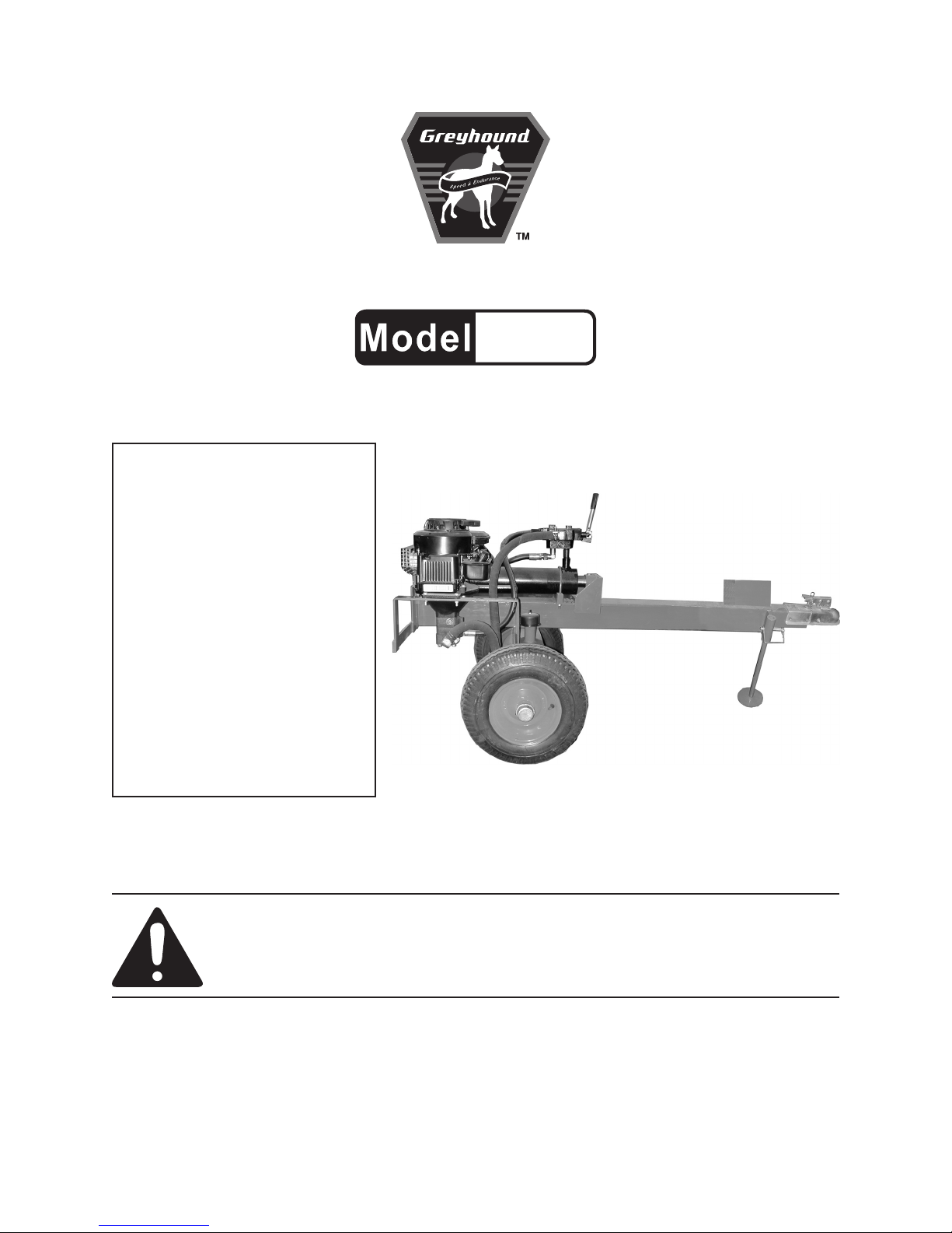
8 TON HYDRAULIC LOG SPLITTER
66519
SET UP, OPERATING, AND SERVICING
INSTRUCTIONS
WARNING!
IMPORTANT INFORMATION
The Hitch Coupler MUST be properly
secured to the hitch ball of the towing
vehicle. After assembly and attachment,
pull up and down on the Hitch Coupler to
make sure the hitch ball is tting snugly in
the Hitch Coupler. There must be no play
between the hitch ball and Hitch Coupler.
If there is play, tighten the Adjustment Nut
until no play is present. If the Adjustment
Nut is too tight, the Handle will not lock.
Carefully read and follow the complete
instructions in this manual BEFORE
setup or use.
If the Coupler is not secured
properly, the ball could come loose
while the Log Splitter is in motion,
possibly causing property damage,
SERIOUS PERSONAL INJURY, or
DEATH.
Distributed exclusively by Harbor Freight Tools®.
3491 Mission Oaks Blvd., Camarillo, CA 93011
Visit our website at: http://www.harborfreight.com
Read this material before using this product.
Failure to do so can result in serious injury.
SAVE THIS MANUAL.
Copyright© 2009 by Harbor Freight Tools®. All rights reserved. No portion of this manual or any artwork
contained herein may be reproduced in any shape or form without the express written consent of
Harbor Freight Tools. Diagrams within this manual may not be drawn proportionally. Due to continuing
improvements, actual product may differ slightly from the product described herein. Tools required for
assembly and service may not be included.
For technical questions or replacement parts, please call 1-800-444-3353.
Page 2

SAVE THIS MANUAL
Keep this manual for the safety warn-
ings and precautions, assembly, operating, inspection, maintenance and cleaning
procedures. Write the product’s serial
number in the back of the manual near the
assembly diagram (or month and year of
purchase if product has no number). Keep
this manual and the receipt in a safe and
dry place for future reference.
IMPORTANT SAFETY
INFORMATION
In this manual, on the labeling,
and all other information
provided with this product:
This is the safety alert
symbol. It is used to alert
you to potential personal
injury hazards. Obey all
safety messages that
follow this symbol to avoid
possible injury or death.
NOTICE is used to
address practices
not related to personal injury.
CAUTION, without
the safety alert
symbol, is used to address
practices not related to
personal injury.
WARNING! Read all instructions.
Failure to follow all instructions
listed below may result in re,
serious injury and/or DEATH.
The warnings and precautions
discussed in this manual cannot
cover all possible conditions and
situations that may occur. It must
be understood by the operator that
common sense and caution are
factors which cannot be built into
this product, but must be supplied
by the operator.
SAVE THESE INSTRUCTIONS
SET UP PRECAUTIONS
Gasoline fuel and fumes are amma-1.
DANGER indicates
a hazardous
situation which, if not
avoided, will result in death or
serious injury.
WARNING
indicates a
hazardous situation which, if
not avoided, could result in
death or serious injury.
CAUTION, used
with the safety
alert symbol, indicates a
hazardous situation which, if
not avoided, could result in
minor or moderate injury.
SKU 66519 For technical questions, please call 1-800-444-3353. Page 2
ble, and potentially explosive. Use
proper fuel storage and handling procedures. Do not store fuel or other
ammable materials nearby.
Have multiple ABC class re extin-2.
guishers nearby.
Operation of this equipment may cre-3.
ate sparks that can start res around
dry vegetation. A spark arrestor may
be required. The operator should
contact local re agencies for laws or
regulations relating to re prevention
requirements.
Set up and use only on a at, level, 4.
well-ventilated surface.
Page 3
Wear ANSI-approved safety goggles, 5.
heavy-duty work gloves, and dust
mask/respirator during set up.
Use only lubricants and fuel recom-6.
mended in the engine manual or in
the Specications chart of this manual.
Do not leave the equipment unat-3.
tended when it is running. Turn off
the equipment (and remove safety
keys, if available) before leaving the
work area.
Rope off work area around the Log 4.
Splitter to keep children and spectators away during operation.
ENGINE PRECAUTIONS
Follow engine precautions and instructions in the included engine
instruction manual.
OPERATING PRECAUTIONS
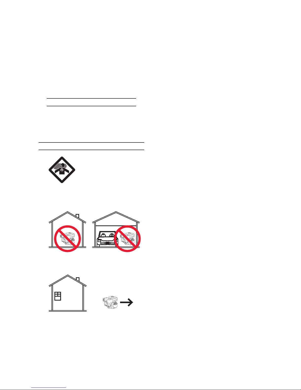
1. CARBON MONOXIDE
HAZARD
Using an engine indoors
CAN KILL YOU IN
MINUTES.
Engine exhaust contains carbon
monoxide. This is a poison you
cannot see or smell.
NEVER use inside a home or garage,
EVEN IF doors and windows are
open.
Never allow children to climb on or 5.
play near Log Splitter even when not
in use.
Observe work area conditions. Do not 6.
use machines or power tools in damp
or wet locations. Don’t expose to rain.
Keep work area well lighted.
People with pacemakers should 7.
consult their physician(s) before
use. Electromagnetic elds in close
proximity to a heart pacemaker could
cause pacemaker interference or
pacemaker failure. Caution is necessary when near the engine’s magneto
or recoil starter.
Use only accessories that are recom-8.
mended by Harbor Freight Tools for
your model. Accessories that may be
suitable for one piece of equipment
may become hazardous when used
on another piece of equipment.
Operate the Log Splitter, with the 9.
wheels blocked, on a dry, level surface capable of supporting the combined weight of the Log Splitter and
logs.
Only use OUTSIDE and far away
from windows, doors, and vents.
Keep children away from the equip-2.
ment, especially while it is operating.
SKU 66519 For technical questions, please call 1-800-444-3353. Page 3
Do not tow the Log Splitter on roads 10.
or highways. This product is not
D.O.T. compliant, and is not road
legal.
Always make sure the hitch coupler 11.
is securely xed to the vehicle before
Page 4

moving it. If the Coupler is not secured properly, the link could come
loose while the trailer is in motion,
possibly causing property damage,
SERIOUS PERSONAL INJURY, or
DEATH.
Take caution as some woods con-12.
tain preservatives such as copper
chromium arsenate (CCA) which
can be toxic. When cutting these
materials extra care should be taken
to avoid inhalation and minimize skin
contact.
ables better control of the equipment
in unexpected situations.
Dress properly. Do not wear loose 20.
clothing or jewelry. Keep hair, clothing and gloves away from moving
parts. Loose clothes, jewelry or long
hair can be caught in moving parts.
Parts, especially exhaust system 21.
components, get very hot during use.
Stay clear of hot parts.
Do not cover the engine or equipment 22.
during operation.
Never split a log that contains any 13.
foreign materials (nails, for example).
Never place your hands or body near 14.
a hydraulic uid leak. High-pressure
uid can be forced under the skin
resulting in serious injury.
Do not use on logs longer than 20” or 15.
with a diameter greater than 8”.
Wear ANSI-approved safety goggles, 16.
NIOSH-approved dust mask/respirator under a full face shield, heavy-duty work gloves, steel-toe work boots
and hearing protection during use.
Do not operate in explosive atmo-17.
spheres, such as in the presence of
ammable liquids, gases, or dust.
Gasoline-powered engines may ignite
the dust or fumes.
Stay alert, watch what you are doing 18.
and use common sense when operating this piece of equipment. Do not
use this piece of equipment while
tired or under the inuence of drugs,
alcohol or medication.
Do not overreach. Keep proper foot-19.
ing and balance at all times. This en-
Keep the equipment, engine, and sur-23.
rounding area clean at all times.
Use the equipment, accessories, etc., 24.
in accordance with these instructions
and in the manner intended for the
particular type of equipment, taking
into account the working conditions
and the work to be performed. Use
of the equipment for operations different from those intended could result
in a hazardous situation.
Do not operate the equipment with 25.
known leaks in the engine’s fuel system.
This product contains or, when used, 26.
produces a chemical known to the
State of California to cause cancer
and birth defects or other reproductive harm. (California Health & Safety
Code § 25249.5, et seq.)
When spills of fuel or oil occur, they 27.
must be cleaned up immediately.
Dispose of uids and cleaning materials as per any local, state, or federal
codes and regulations. Store oil rags
in a bottom-ventilated, covered, metal
container.
SKU 66519 For technical questions, please call 1-800-444-3353. Page 4
Page 5

Keep hands and feet away from 28.
moving parts. Do not reach over or
across equipment while operating.
Wear ANSI-approved safety goggles, 4.
heavy-duty work gloves, and dust
mask/respirator during service.
Before use, check for misalignment 29.
or binding of moving parts, breakage
of parts, and any other condition that
may affect the equipment’s operation.
If damaged, have the equipment
serviced before using. Many ac-
cidents are caused by poorly maintained equipment.
Use the correct equipment for the 30.
application. Do not modify the equipment and do not use the equipment
for a purpose for which it is not intended.
SERVICE PRECAUTIONS
Before service, maintenance, or 1.
cleaning:
Slide the Fuel Valve to its a.
“CLOSED” position.
Maintain labels and nameplates on 5.
the equipment. These carry important information. If unreadable or
missing, contact Harbor Freight Tools
for a replacement.
Have the equipment serviced by a 6.
qualied repair person using only
identical replacement parts. This will
ensure that the safety of the equipment is maintained. Do not attempt
any service or maintenance procedures not explained in this manual
or any procedures that you are uncertain about your ability to perform
safely or correctly.
Store equipment out of the reach of 7.
children.
Follow scheduled engine and equip-8.
ment maintenance.
Allow the engine to completely b.
cool.
Then, remove the spark plug c.
wire(s) from the spark plug(s).
Keep all safety guards in place and in 2.
proper working order. Safety guards
include mufer, air cleaner, mechanical guards, and heat shields, among
other guards.
Do not alter or adjust any part of 3.
the equipment or its engine that is
sealed by the manufacturer or dis-
tributor. Only a qualied service
technician may adjust parts that
may increase or decrease governed engine speed.
Refueling:9.
Do not smoke, or allow sparks, a.
ames, or other sources of ignition
around the equipment, especially
when refuelling.
Do not rell the fuel tank while the b.
engine is running or hot.
Do not ll fuel tank to the top. Leave c.
a little room for the fuel to expand as
needed.
Refuel in a well-ventilated area only.d.
SAVE THESE
INSTRUCTIONS.
SKU 66519 For technical questions, please call 1-800-444-3353. Page 5
Page 6
BASIC SPECIFICATIONS
Hydraulic Capacity 8 Tons
Hydraulic Fluid 1.5 Gallons
10W AW Hydraulic
Hydraulic Fluid
Reservoir
Rotation viewed from PTO
(power takeoff - the output shaft)
Maximum Log Size 20” long x 8” dia.
Towing
Coupler Ball Required 1-7/8”
Wheel Size
Tire Air Pressure 42 PSI (cold)
uid or Dexron® III
automatic transmission
uid. Change every 100
hours of use.
Counterclockwise
For off-road use only
(not DOT approved)
Wheel: 15” dia.
Hub: 8-1/2”
Wheel base: 20”
Note: Engine specications are found in
the engine manual supplied with this
equipment.
UNPACKING
When unpacking, make sure that the
item is intact and undamaged. If any parts
are missing or broken, please call Harbor
Freight Tools at the number shown on the
cover of this manual as soon as possible.
TO PREVENT
SERIOUS INJURY
FROM ACCIDENTAL
STARTING:
Slide the Fuel Valve of the
equipment to its “CLOSED”
position, wait for the engine to
cool, and disconnect the
spark plug wire(s) before
assembling or making any
adjustments to the equipment.
TO PREVENT
SERIOUS INJURY:
Operate only with proper
spark arrestor installed.
Operation of this equipment
may create sparks that
can start res around dry
vegetation.
A spark arrestor may be
required.
The operator should contact
local re agencies for laws
or regulations relating to re
prevention requirements.
Note: For additional information regarding
the parts listed in the following pages,
refer to the Assembly Diagram near
the end of this manual.
SET UP INSTRUCTIONS
Read the ENTIRE IMPORTANT
SAFETY INFORMATION
section at the beginning of this
manual including all text under
subheadings therein before set
up or use of this product.
SKU 66519 For technical questions, please call 1-800-444-3353. Page 6
Assembly
To assemble the Wheels (20):1.
Insert one Axle (22) into the Wheel a.
Shaft Opening under the Main Body
(23).
Align the small hole on the side of b.
the Axle with the hole in the side of
the Wheel Shaft.
Insert the Support Leg Pin (28).c.
Secure the Support Leg Pin with the d.
Support Leg Clip (27).
REV 09h
Page 7

Slide the Wheel and assembly parts e.
(18-21) onto the Axle (22).
Thread the Castle Nut (17) onto the f.
Axle and x in place with the Cotter
Pin (16).
Cover the end with the Dust-Proof g.
Cap (15).
Repeat steps h. a through g for the
other Wheel.
To assemble the Control Handle (36):2.
Slide the Control Handle between a.
the U-shaped bars on the direction
Valve (41).
Align the small hole on the side of b.
the Control Handle (36) with the
holes on the Direction Valve (41)
bars.
Insert the Pin (38).c.
Secure the Pin with the Clip (39).d.
SKU 66519 For technical questions, please call 1-800-444-3353. Page 7
Page 8
OPERATING INSTRUCTIONS
Read the ENTIRE IMPORTANT
SAFETY INFORMATION
section at the beginning of this
manual including all text under
subheadings therein before set
up or use of this product.
Engine Operation
Inspect engine and equipment
looking for damaged, loose,
and missing parts before
set up and starting. If any
problems are found, do not use
equipment until xed properly.
Start Procedure
Before starting the engine:
Follow the Set Up Instruc-a.
tions to prepare the equipment. Follow all instructions
in the separate engine manual provided with the engine.
Inspect the equipment and b.
engine.
Fill the engine with the c.
proper amount and type of
fuel and oil. See Checking
the Fuel Level of the Engine
Manual, page 9.
Read the Equipment Opera-d.
tion section that follows.
Equipment Operation
Pre-Operation Procedures
mission uid. You need to change the
uid every 100 hours of usage.
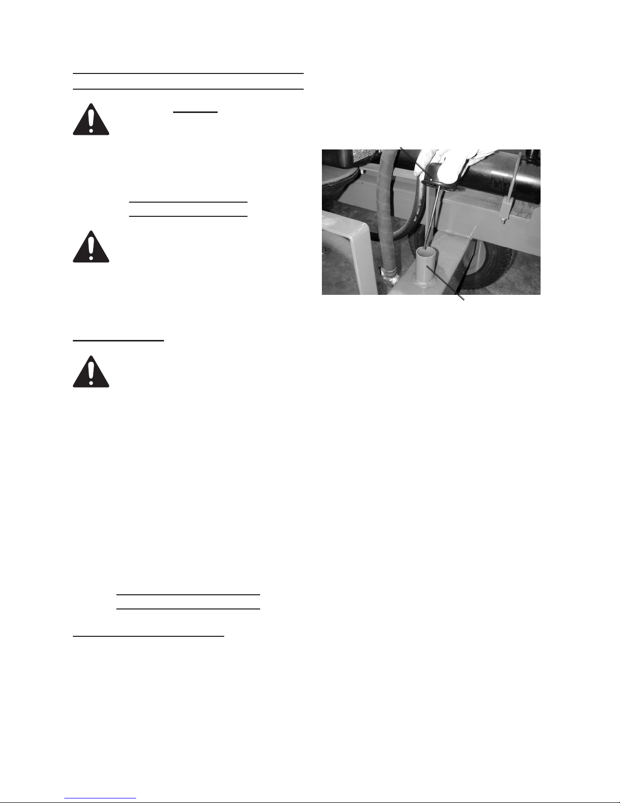
Hydraulic Fluid
Fill Tube Cap
with Dip Stick
Figure 1
Hydraulic Fluid
Fill Tube
2. To add hydraulic uid:
Pull out the Hydraulic Fluid Fill Tube a.
Cap.
Wipe off and reinsert fully.b.
Pull out again and check the level on c.
the attached dip stick.
Add hydraulic uid if needed.d.
Replace the Hydraulic Fluid Fill Tube e.
Cap.
Inate tires to 42 PSI.3.
Remove Wheel Bearing Dust Proof 4.
Caps (15) and remove Bearings.
Completely pack with bearing grease.
Replace Bearings and Wheel Bearing Covers. If you are not familiar
with this procedure, have a qualied
mechanic do it.
Check and add hydraulic uid to the 1.
Hydraulic Fluid Tank as needed (up
to 1.5 gallons). You can use 10 W
AW or Dextron® lll automatic trans-
SKU 66519 For technical questions, please call 1-800-444-3353. Page 8
REV 09h
Page 9
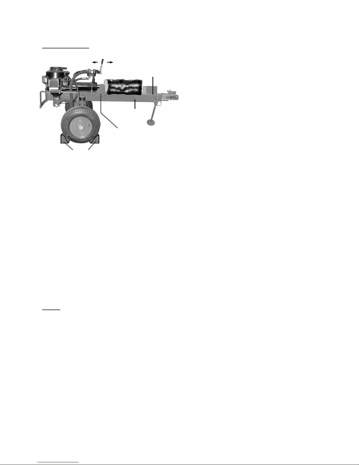
Splitting Logs
Ram Control Handle (36)
Reverse
Forward
Cutting Wedge
If the log is not securely seated, re-6.
peat steps 3 - 5 to reposition the log
for splitting.
Stand to one side of the Engine, then 7.
push the Ram Control Handle forward until the log is split.
Main Body (23)
Sliding Seat (33)
Wheel Chocks
(not included)
Figure 2
1. After locating Log Splitter in a wide
open, at work area with no nearby
obstructions, place wheel chocks (not
supplied) on each side of the wheels
to keep the Log Splitter from moving.
See Figure 2.
Start and operate the engine accord-2.
ing to the provided engine manual.
Allow the engine to run for a few
minutes to warm up and to build up
pressure in the hydraulic system.
Pull back on Ram Control Handle to 3.
retract the Ram, then move to neutral
(center) position.
When the log is split, pull back on the 8.
Ram Control Handle to retract the
Ram.
Remove the log pieces.9.
Prepare the next log to be split. The 10.
Log Splitter hydraulic system can split
up to four logs per minute.
Note: When using the Ram Control Han-
dle, stand well clear of the cutting
wedge and the area where the log
will rest on the Main Body (23).
Center a log on the Main Body (23), 4.
no more than 20” long and 14” in
diameter.
Momentarily push forward lightly on 5.
the Ram Control Handle until the log
is locked in place between the Sliding
Seat (33) and the Cutting Wedge. If
the log is correctly seated, continue
with Step 7.
SKU 66519 For technical questions, please call 1-800-444-3353. Page 9
Page 10

SERVICING
Storage
TO PREVENT
SERIOUS INJURY
FROM ACCIDENTAL
STARTING:
Slide the Fuel Valve of the
equipment to its “CLOSED”
position, wait for the engine to
cool, and disconnect the
spark plug wire(s) before
performing any inspection,
maintenance, or cleaning
procedures.
TO PREVENT
SERIOUS INJURY
FROM EQUIPMENT FAILURE:
Do not use damaged
equipment. If abnormal noise,
vibration, or excess smoking
occurs, have the problem
corrected before further use.
Maintenance Procedures
Many maintenance procedures,
including those not detailed
in this manual, will need to
be performed by a qualied
technician for safety. If you
have any doubts about your
ability to safely service the
equipment or engine, have a
qualied technician service the
equipment instead.
Wait for engine to cool, then clean 1.
equipment with clean cloth and compressed air.
Clean the engine and/or prepare it for 2.
storage according to engine manual
instructions.
Apply a thin coat of rust preventive oil 3.
to all uncoated metal parts.
Cover and store in a dry, well-ventilat-4.
ed area out of reach of children.
For cold weather operation, store 5.
the equipment in a cool dry area to
prevent condensation and premature
wear.
Transportation
BEFORE 1. Transporting, check the
Tires for wear and proper ination (60
PSI, cold).
Attach safety chains (not included) as 2.
per DOT requirments.
Before Transporting and at 500 MILE 3.
intervals during every trip, check and
tighten the Tire Lug Nuts to 85-90
ft-lb.
Engine Maintenance and Service
Follow the instructions found in the
included engine manual.
SKU 66519 For technical questions, please call 1-800-444-3353. Page 10
Page 11

PARTS LIST
Part Description Qty
1 Engine 1
2 Bolt M8x45 3
3 Flat Washer 8mm 8
4 Nut M8 18
5 Shaft Connector 1
6 Flat Key B 4.8 x 4.8 x 35 1
7 Lock Screw 8x8 1
8 Flange 1
9 Connector 1
10 Oil Pump 1
11 Bolt M8x25 4
12 Dip Stick 1
13 Rubber Hose 1
14 Oil Pump Connector/Low Pressure 2
15 Dust-Proof Cap 2
16 Cotter Pin 4x36 2
17 Castle Nut M20 2
18 Flat Washer 20mm 2
19 Bearing L44643 4
20 Wheel Assembly 2
21 Dust-Proof Ring 2
22 Axle 2
23 Main Body 1
24 Bolt M10x90 2
25 Hitch Coupler 1
Part Description Qty
26 Nut M10 2
27 Support Leg Clip 3
28 Support Leg Pin 3
29 Support Leg 1
30 Bafe 2
31 Bolt M8x30 6
32 Sliding Pad 1
33 Sliding Seat Assembly 1
34 Bolt M8x70 1
35 Connector 12A 1
36 Ram Control Handle 1
37 Handle Grip 1
38 Pin B6x26 1
39 Clip 1
40 Pipe Clip 35 4
41 Direction Valve 1
42
43 Rubber Hose I 1
44 Rubber Hose II 1
45
46 Hoop 2
47 Hydraulic Cylinder 1
48 Connector for Cylinder and Valve 1
Direction Valve Connector/High
Pressure
Oil Pump Connector/High
Pressure
1
3
Record Product’s Serial Number Here:
Note: If product has no serial number, record month and year of purchase instead.
Note: Some parts are listed and shown for illustration purposes only, and are not avail-
able individually as replacement parts.
SKU 66519 For technical questions, please call 1-800-444-3353. Page 11
Page 12
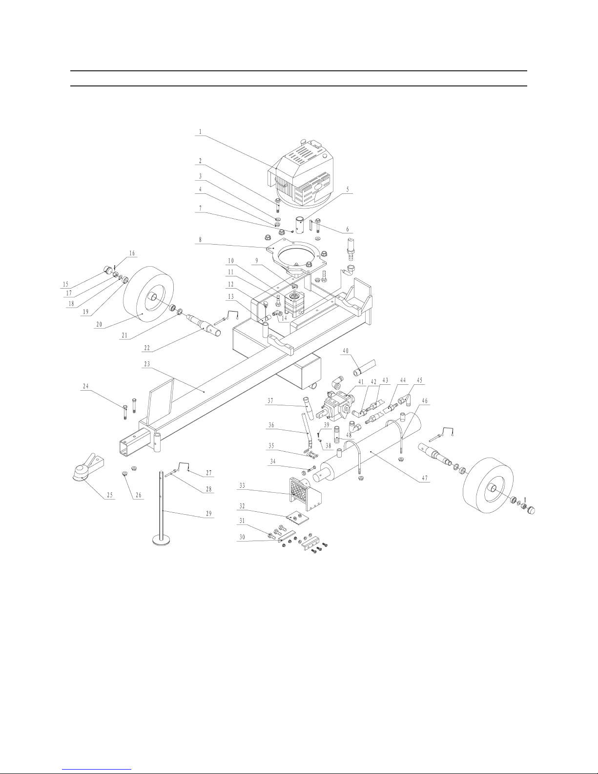
ASSEMBLY DIAGRAM
SKU 66519 For technical questions, please call 1-800-444-3353. Page 12
Page 13

PLEASE READ THE FOLLOWING CAREFULLY
THE MANUFACTURER AND/OR DISTRIBUTOR HAS PROVIDED THE PARTS LIST AND ASSEMBLY
DIAGRAM IN THIS MANUAL AS A REFERENCE TOOL ONLY. NEITHER THE MANUFACTURER OR
DISTRIBUTOR MAKES ANY REPRESENTATION OR WARRANTY OF ANY KIND TO THE BUYER THAT
HE OR SHE IS QUALIFIED TO MAKE ANY REPAIRS TO THE PRODUCT, OR THAT HE OR SHE IS
QUALIFIED TO REPLACE ANY PARTS OF THE PRODUCT. IN FACT, THE MANUFACTURER AND/
OR DISTRIBUTOR EXPRESSLY STATES THAT ALL REPAIRS AND PARTS REPLACEMENTS SHOULD
BE UNDERTAKEN BY CERTIFIED AND LICENSED TECHNICIANS, AND NOT BY THE BUYER. THE
BUYER ASSUMES ALL RISK AND LIABILITY ARISING OUT OF HIS OR HER REPAIRS TO THE
ORIGINAL PRODUCT OR REPLACEMENT PARTS THERETO, OR ARISING OUT OF HIS OR HER
INSTALLATION OF REPLACEMENT PARTS THERETO.
SKU 66519 For technical questions, please call 1-800-444-3353. Page 13
Page 14

LIMITED 90 DAY WARRANTY
Harbor Freight Tools Co. makes every effort to assure that its products meet high
quality and durability standards, and warrants to the original purchaser that this product is free from defects in materials and workmanship for the period of 90 days from
the date of purchase. This warranty does not apply to damage due directly or indirectly,
to misuse, abuse, negligence or accidents, repairs or alterations outside our facilities,
criminal activity, improper installation, normal wear and tear, or to lack of maintenance.
We shall in no event be liable for death, injuries to persons or property, or for incidental,
contingent, special or consequential damages arising from the use of our product. Some
states do not allow the exclusion or limitation of incidental or consequential damages, so
the above limitation of exclusion may not apply to you. THIS WARRANTY IS EXPRESSLY IN LIEU OF ALL OTHER WARRANTIES, EXPRESS OR IMPLIED, INCLUDING THE
WARRANTIES OF MERCHANTABILITY AND FITNESS.
To take advantage of this warranty, the product or part must be returned to us with
transportation charges prepaid. Proof of purchase date and an explanation of the complaint must accompany the merchandise. If our inspection veries the defect, we will either repair or replace the product at our election or we may elect to refund the purchase
price if we cannot readily and quickly provide you with a replacement. We will return repaired products at our expense, but if we determine there is no defect, or that the defect
resulted from causes not within the scope of our warranty, then you must bear the cost
of returning the product.
This warranty gives you specic legal rights and you may also have other rights
which vary from state to state.
3491 Mission Oaks Blvd. • PO Box 6009 • Camarillo, CA 93011 • (800) 444-3353
SKU 66519 For technical questions, please call 1-800-444-3353. Page 14
 Loading...