

Page 1
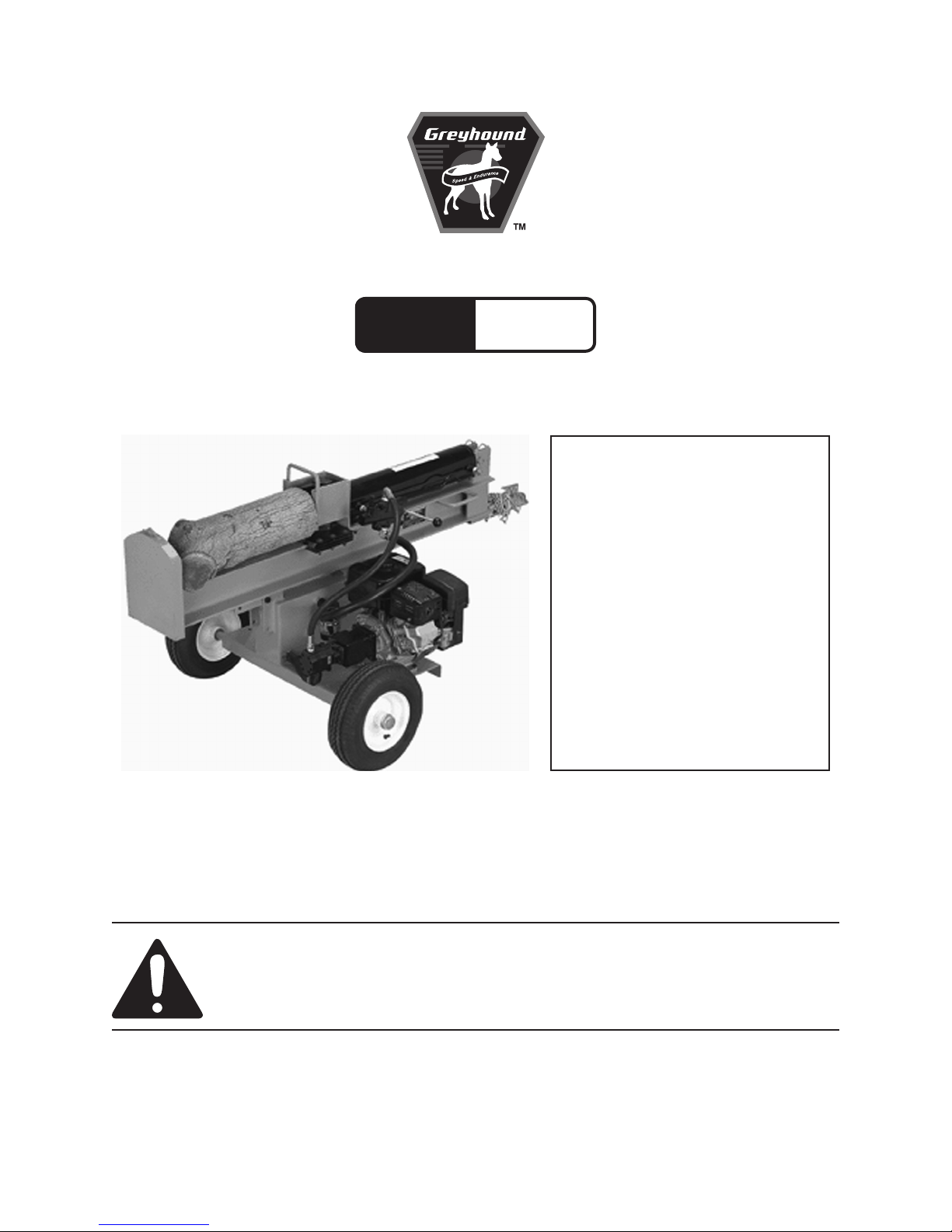
22 TON LOG SPLITTER
Model
65075
SET UP, OPERATING, AND SERVICING
INSTRUCTIONS
WARNING!
IMPORTANT INFORMATION
The Hitch Coupler MUST be properly
secured to the hitch ball of the towing vehicle.
After assembly and attachment, pull up and
down on the Hitch Coupler to make sure the
hitch ball is tting snugly in the Hitch Coupler.
There must be no play between the hitch
ball and Hitch Coupler. If there is play, tighten
the Adjustment Nut until no play is present. If
the Adjustment Nut is too tight, the Handle
will not lock. Carefully read and follow
the complete instructions in this manual
BEFORE setup or use.
If the Coupler is not secured
properly, the ball could come loose
while the Log Splitter is in motion,
possibly causing property damage,
SERIOUS PERSONAL INJURY, or
DEATH.
Diagrams within this manual may not be drawn proportionally.
Due to continuing improvements, actual product may differ slightly from the product described herein.
Distributed exclusively by Harbor Freight Tools®.
3491 Mission Oaks Blvd., Camarillo, CA 93011
Visit our website at: http://www.harborfreight.com
Read this material before using this product.
Failure to do so can result in serious injury.
SAVE THIS MANUAL.
Copyright© 2008 by Harbor Freight Tools®. All rights reserved. No portion of this
manual or any artwork contained herein may be reproduced in any shape or form
without the express written consent of Harbor Freight Tools.
For technical questions or replacement parts, please call 1-800-444-3353.
Page 2

CONTENTS
IMPORTANT SAFETY
INFORMATION ............................ 4
OPERATING PRECAUTIONS ............ 5
SERVICE PRECAUTIONS ............. 6
REFUELING: .................................7
BASIC SPECIFICATIONS ............. 8
UNPACKING .................................. 8
SET UP INSTRUCTIONS ............... 8
ASSEMBLY.........................................8
PACKING THE BEARINGS. .........8
HUB AND WHEEL ASSEMBLY .. 10
CONNECTING THE RAIL
ASSEMBLY TO THE OIL
TANK ........................................10
FUEL FILTER REPLACEMENT
(IF EQUIPPED) .........................16
CLEANING, MAINTENANCE, AND
LUBRICATION SCHEDULE .......... 17
AFTER 20 OPERATION HOUR
BREAK-IN PERIOD: ................17
AFTER EVERY 25 OPERATION
HOURS: ....................................17
AFTER EVERY 50 OPERATION
HOURS: ....................................17
AFTER EVERY 100
OPERATION HOURS: ..............17
AFTER EVERY 300
OPERATION HOURS: ..............17
STORAGE ........................................17
TRANSPORT MAINTENANCE ........18
TROUBLESHOOTING ...................... 19
GENERAL PARTS LIST .............. 22
OPERATING INSTRUCTIONS .... 10
STARTING THE ENGINE .................10
CHECKING ENGINE OIL LEVEL 10
ENGINE DIAGRAM ...................... 11
CHECKING FUEL LEVEL ........... 12
CHECKING AND FILLING
HYDRAULIC FLUID ................. 12
START PROCEDURE .................12
BREAK-IN PERIOD ....................13
EQUIPMENT OPERATION ...............13
TRANSPORTING THE LOG
SPLITTER .................................14
TECHNICAL SPECIFICATIONS .. 15
SERVICING .................................. 15
MAINTENANCE PROCEDURES .....15
ENGINE OIL CHANGE ...............15
AIR FILTER ELEMENT
MAINTENANCE .......................15
SPARK PLUG MAINTENANCE .. 16
GENERAL ASSEMBLY
DIAGRAM .................................. 23
CYLINDER HEAD PARTS LIST
& DIAGRAM .............................. 24
CRANK CASE PARTS LIST &
DIAGRAM .................................. 25
CRANK CASE COVER PARTS
LIST AND DIAGRAM ................. 26
CRANKSHAFT/PISTON PARTS
LIST & DIAGRAM ...................... 27
GAS DISTRIBUTION
ADJUSTMENT SYSTEM
PARTS LIST & DIAGRAM ......... 28
STARTER SUBASSEMBLY
PARTS LIST & DIAGRAM ......... 29
Page 2SKU 65075 For technical questions, please call 1-800-444-3353.
Page 3

DIVERSION ASSEMBLY PARTS
LIST & DIAGRAM ...................... 30
CARBURETOR PARTS LIST &
DIAGRAM .................................. 31
FLYWHEEL/COIL ASSEMBLY
PARTS LIST & DIAGRAM ......... 32
CONTROL SYSTEM PARTS
LIST & DIAGRAM ...................... 33
AIR CLEANER PARTS LIST &
DIAGRAM .................................. 34
MUFFLER PARTS LIST &
DIAGRAM .................................. 35
FUEL TANK PARTS LIST &
DIAGRAM .................................. 36
CARBON CANISTER
ASSEMBLY ................................ 37
LIMITED 1 YEAR / 90 DAY
WARRANTY .............................. 38
EMISSION CONTROL SYSTEM
WARRANTY .............................. 38
Page 3SKU 65075 For technical questions, please call 1-800-444-3353.
Page 4

SAVE THIS MANUAL
Keep this manual for the safety warnings and precautions, assembly, operating, inspection, maintenance and cleaning
procedures. Write the product’s serial
number in the back of the manual near the
assembly diagram (or month and year of
purchase if product has no number). Keep
this manual and the receipt in a safe and
dry place for future reference.
IMPORTANT SAFETY
INFORMATION
In this manual, on the labeling,
and all other information
provided with this product:
This is the safety alert
symbol. It is used to alert
you to potential personal
injury hazards. Obey all
safety messages that
follow this symbol to avoid
possible injury or death.
Notice
CAUTION
NOTICE is used to
address practices
not related to personal injury.
CAUTION, without
the safety alert
symbol, is used to address
practices not related to
personal injury.
WARNING! Read all instructions.
Failure to follow all instructions
listed below may result in re,
serious injury and/or DEATH.
The warnings and precautions
discussed in this manual cannot
cover all possible conditions and
situations that may occur. It must
be understood by the operator that
common sense and caution are
factors which cannot be built into
this product, but must be supplied
by the operator.
SAVE THESE INSTRUCTIONS
SET UP PRECAUTIONS
DANGER indicates
DANGER
situation which, if not
avoided, will result in death or
serious injury.
WARNING
WARNING
hazardous situation which, if
not avoided, could result in
death or serious injury.
CAUTION, used
CAUTION
alert symbol, indicates a
hazardous situation which, if
not avoided, could result in
minor or moderate injury.
a hazardous
indicates a
with the safety
Gasoline fuel and fumes are amma-1.
ble, and potentially explosive. Use
proper fuel storage and handling procedures. Do not store fuel or other
ammable materials nearby.
Have multiple ABC class re extin-2.
guishers nearby.
This equipment has a spark arresting 3.
mufer included. A spark arresting
mufer is required by law in Califor-
nia, on some US Forest Service land,
and possibly in other areas or situations.
Set up and use only on a at, level, 4.
well-ventilated surface.
Page 4SKU 65075 For technical questions, please call 1-800-444-3353.
Page 5
Wear ANSI-approved safety goggles, 5.
heavy-duty work gloves, and dust
mask/respirator during set up and
use.
Use only oil and fuel recommended 6.
in the “Specications” section of this
manual.
OPERATING PRECAUTIONS
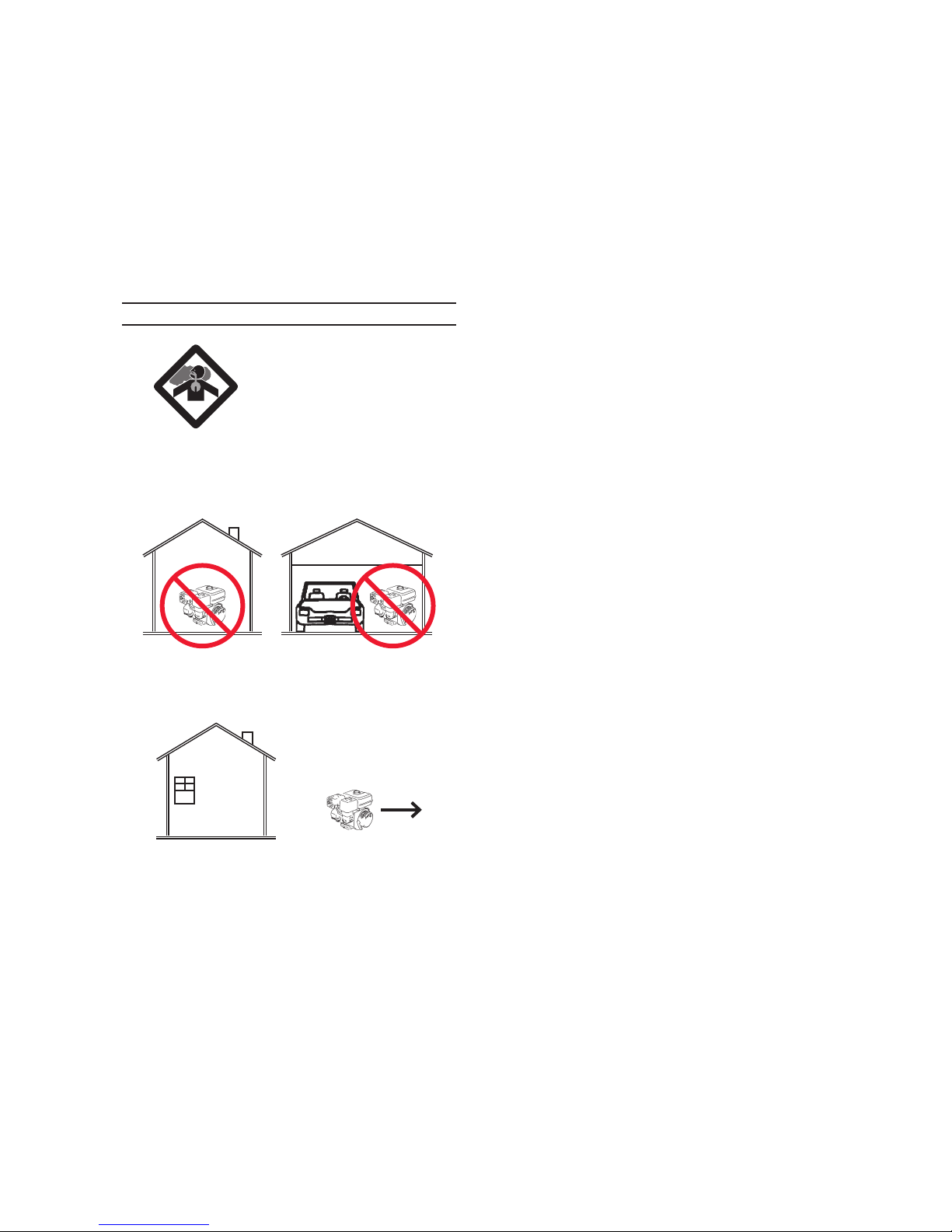
1. CARBON MONOXIDE
HAZARD
Using an engine indoors
CAN KILL YOU IN
MINUTES.
Engine exhaust contains carbon
monoxide. This is a poison you
cannot see or smell.
Wear ANSI-approved safety goggles 4.
and hearing protection during use.
Operate the Log Splitter, with the 5.
wheels blocked, on a dry, level surface capable of supporting the combined weight of the Log Splitter and
logs.
Do not drive the Log Splitter on 6.
roads or highways. This product
is not D.O.T. compliant, and is not
road legal.
Always make sure the hitch coupler 7.
is securely xed to the vehicle before
moving it. If the Coupler is not secured properly, the link could come
loose while the trailer is in motion,
possibly causing property damage,
SERIOUS PERSONAL INJURY, or
DEATH.
NEVER use inside a home or garage,
EVEN IF doors and windows are
open.
Only use OUTSIDE and far away
from windows, doors, and vents.
Keep children away from the equip-2.
ment, especially while it is operating.
Do not leave the equipment unat-3.
tended when it is running. Turn off
the equipment (and remove safety
keys, if available) before leaving the
work area.
Never split a log that contains any 8.
foreign materials (nails, for example).
Never place your hands or body near 9.
a hydraulic uid leak. High-pressure
uid can be forced under the skin
resulting in serious injury.
Do not use on logs longer than 25” or 10.
with a diameter greater than 8”.
People with pacemakers should 11.
consult their physician(s) before
use. Electromagnetic elds in close
proximity to a heart pacemaker could
cause pacemaker interference or
pacemaker failure. Caution is necessary when near the engine’s magneto
or recoil starter.
Use only accessories that are recom-12.
mended by Harbor Freight Tools for
your model. Accessories that may be
suitable for one piece of equipment
may become hazardous when used
on another piece of equipment.
Page 5SKU 65075 For technical questions, please call 1-800-444-3353.
Page 6

Do not operate in explosive atmo-13.
spheres, such as in the presence of
ammable liquids, gases, or dust.
Gasoline-powered engines may ignite
the dust or fumes.
Stay alert, watch what you are doing 14.
and use common sense when operating a piece of equipment. Do not use
a piece of equipment while tired or
under the inuence of drugs, alcohol
or medication.
Do not overreach. Keep proper foot-15.
ing and balance at all times. This enables better control of the equipment
in unexpected situations.
Dress properly. Do not wear loose 16.
clothing or jewelry. Keep hair, clothing and gloves away from moving
parts. Loose clothes, jewelry or long
hair can be caught in moving parts.
Parts of the Log Splitter, especially 17.
exhaust system components, get
very hot during use. Stay clear of hot
parts.
Do not cover the engine or equipment 18.
during operation.
Keep the equipment, engine, and sur-19.
rounding area clean at all times.
Use the equipment, accessories, etc., 20.
in accordance with these instructions
and in the manner intended for the
particular type of equipment, taking
into account the working conditions
and the work to be performed. Use
of the equipment for operations different from those intended could result
in a hazardous situation.
Do not operate the equipment with 21.
known leaks in the engine’s fuel system.
This product contains or, when used, 22.
produces a chemical known to the
State of California to cause cancer
and birth defects or other reproductive harm. (California Health & Safety
Code § 25249.5, et seq.)
WARNING: The brass components 23.
of this product contain lead, a chemical known to the State of California
to cause birth defects (or other reproductive harm). (California Health &
Safety code § 25249.5, et seq.)
When spills of fuel or oil occur, they 24.
must be cleaned up immediately.
Dispose of uids and cleaning materials as per any local, state, or federal
codes and regulations. Store oil rags
in a bottom-ventilated, covered, metal
container.
Keep hands and feet away from 25.
moving parts. Do not reach over or
across equipment while operating.
Before use, check for misalignment 26.
or binding of moving parts, breakage
of parts, and any other condition that
may affect the equipment’s operation.
If damaged, have the equipment
serviced before use. Many ac-
cidents are caused by poorly maintained equipment.
Use the correct equipment for the 27.
application. Do not modify the equipment and do not use the equipment
for a purpose for which it is not intended.
SERVICE PRECAUTIONS
Before service, maintenance, or 1.
cleaning:
Turn the engine switch to its a.
“OFF” position.
Page 6SKU 65075 For technical questions, please call 1-800-444-3353.
Page 7

Allow the engine to completely b.
cool.
Then, remove the spark plug c.
wire(s) from the spark plug(s).
Keep all safety guards in place and in 2.
proper working order. Safety guards
include mufer, air cleaner, mechanical guards, and heat shields, among
other guards.
Do not alter or adjust any part of 3.
the equipment or its engine that is
sealed by the manufacturer or dis-
tributor. Only a qualied service
technician may adjust parts that
may increase or decrease governed engine speed.
Wear ANSI-approved safety goggles, 4.
heavy-duty work gloves, and dust
mask/respirator during use and service.
Refueling:
Do not smoke, or allow sparks, 1.
ames, or other sources of ignition
around the equipment, especially
when refuelling.
Do not rell the fuel tank while the 2.
engine is running or hot.
Do not ll fuel tank to the top. Leave 3.
a little room for the fuel to expand as
needed.
Refuel in a well-ventilated area only.4.
SAVE THESE
INSTRUCTIONS.
Maintain labels and nameplates on 5.
the equipment. These carry important information. If unreadable or
missing, contact Harbor Freight Tools
for a replacement.
Have the equipment serviced by a 6.
qualied repair person using only
identical replacement parts. This will
ensure that the safety of the equipment is maintained. Do not attempt
any service or maintenance procedures not explained in this manual
or any procedures that you are uncertain about your ability to perform
safely or correctly.
Store equipment out of the reach of 7.
children.
Follow scheduled engine and equip-8.
ment maintenance.
Page 7SKU 65075 For technical questions, please call 1-800-444-3353.
Page 8

BASIC SPECIFICATIONS
SET UP INSTRUCTIONS
Fuel
Type
Capacity 0.95 Gallons
Type SAE:
Engine Oil
Capacity 0.63 Quarts
Hydraulic Fluid
Capacity
Engine Speed 3,600 RPM
Engine Family 7CGPS.1961 GA : EM
Maximum Log Size 25” L x 8” Diameter
Maximum Pressure 2,800 PSI
Tire Air Pressure 60 PSI (cold)
86+ octane unleaded
gasoline
10W 30 above 32° F
5W30 at 32° F or below
2.5 Gallons
Note: Additional specications found in
the TECHNICAL ENGINE SPECIFICATIONS chart in this manual.
The emission control system for this
engine is warranted for standards set by
the U.S. Environmental Protection Agency
and by the California Air Resources Board
(also known as CARB). For warranty
information, refer to the last pages of this
manual.
At high altitudes, the engine’s carburetor, governor (if so equipped), and any
other parts that control the fuel-air ratio will
need to be adjusted by a qualied mechanic to allow efcient high-altitude use
and to prevent damage to the engine and
any other devices used with this product.
UNPACKING
Read the ENTIRE IMPORTANT
SAFETY INFORMATION
section at the beginning of this
manual including all text under
subheadings therein before set
up or use of this product.
Risk of accidental
WARNING
starting; resulting
in serious personal injury.
Turn the Power Switch of the
equipment to its “OFF”
position, wait for the engine to
cool, and unplug the spark
plug wire(s) before
assembling or making any
adjustments to the equipment.
Note: For additional information regarding
the parts listed in the following pages,
refer to the Assembly Diagram near
the end of this manual.
Assembly
This equipment has a spark arresting 1.
mufer included. A spark arresting
mufer is required by law in Califor-
nia, on some US Forest Service land,
and possibly in other areas or situations.
Due to the size of the Log Splitter and 2.
its components, assistance may be
required during the entire assembly
process.
When unpacking, check to make sure
that the item is intact and undamaged. If
any parts are missing or broken, please
call Harbor Freight Tools at the number
shown on the cover of this manual as soon
as possible.
Packing the bearings.
Using a suitable solvent, clean the 3.
bearings and the rest of the parts in
the Hub assembly. The parts must be
cleaned even if they are new or appear clean.
Allow all pieces to dry completely.4.
Page 8SKU 65075 For technical questions, please call 1-800-444-3353.
Page 9
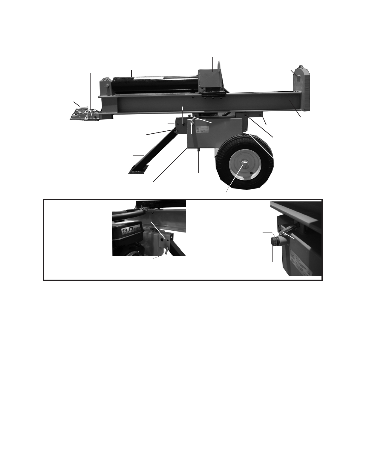
Safety Chain
FIGURE 2
FIGURE 3
Push Pin (26)
Hydraulic Oil Fill Plug (37)
with air inlet hole
Close-up of Push Pin (26) securing the
Front Leg Assembly (11) to the bracket
on the Oil Tank Assembly (10B).
Second Push Pin (26) secures
Rail Assembly (2), and is removed
for vertical log splitting.
Horizontal transport hole
Air Inlet Hole
with Hook (4)
Hitch
Coupler (9)
Horizontal transport hole
Push Pin (26) and
Hair Pin Clip (29)
Front Leg Assembly (11)
FIGURE 1
Slide Assembly (3)
Cylinder (1)
Hex Nut (17) is attached to Hex Bolt (16)
Push Pin (26)
Oil Plug (37)
with air inlet hole
Oil Drain Plug
Hydraulic Oil Tank
Wheel Cap (61)
Base
Place Log Here
Rail Assembly
(2)
Vertical Position Hole
Hex Nut (17) is
attached to Hex
Bolt (16)
Vertical position
locking hole
Page 9SKU 65075 For technical questions, please call 1-800-444-3353.
Page 10

Place fresh, clean bearing grease in 5.
the packer.
With the grease-lled bearing packer 6.
in one hand and the bearing in the
other, press the bear ing into the
grease, forcing the grease inside the
slots in the bearing, continue doing
this until every slot in the bearing is
completely full of grease.
Hub and Wheel Assembly
Put a Seal (59) and Bearing (49) on 7.
the Axle and then put the Tire (48) on
the Axle.
With each Tire in place, add a Wash-8.
er (50) and a Spindle Nut (51) onto
the ends of the Axles. Tighten the
Spindle Nuts to 20-25 Ft.-Lbs. and
turn each tire several times to seat
the bearing. Back off the Spindle Nut
one half turn. Insert a Cotter Pin (25)
through both the Axle and the Spindle
Nut (51) and bend the end of the Pin
back to hold it in place. Last, tap on a
Wheel Cap (61).
Connecting the Rail Assembly to the Oil
Tank
Insert the Front Leg Assembly (11) 9.
into the bracket on the Oil Tank As-
sembly (10B). Insert the remaining
Hex Bolt (16) through the hole in the
middle of the bracket of the Oil Tank
Assembly. Secure it with a Hex Nut
(17) and a Hex Bolt (16).
Note: When travelling, remove the Push
Pin (26) and Hair Pin Clip (29) and lift
the Front Leg Assembly up so that it
is parallel to the Rail Assembly. Re-
place the Push Pin (26) and Hair Pin
Clip (29) into the Horizontal Transport
Hole shown just above the Oil Plug.
To connect the Rail Assembly (2) to 10.
the Oil Tank Assembly, insert a Hex
Bolt (16) into the middle hole of the
“L” shaped bracket on the Oil Tank
Assembly. Secure it with a Hex Nut
(17).
In FIGURES 1 and 2 (see next page), 11.
the Rail Assembly (2) is shown in
Horizontal mode for opera tion and
travel (as mentioned above, the Front
Leg Assembly (11) must be secured
up in the horizontal position when
travelling).
OPERATING INSTRUCTIONS
Read the ENTIRE IMPORTANT
SAFETY INFORMATION
section at the beginning of this
manual including all text under
subheadings therein before set
up or use of this product.
Starting the Engine
Inspect engine and equipment
looking for damaged, loose,
and missing parts before
set up and starting. If any
problems are found, do not use
equipment until xed properly.
Checking Engine Oil Level
CAUTION! Your Warranty is VOID if the
engine’s crankcase is not properly
lled with oil before each use. Before
each use, check the oil level. Do not
run the engine with low or no engine
oil. Running the engine with no or
low engine oil WILL permanently
damage the engine.
Clean the Oil Filler Cap and the area 1.
around it.
Page 10SKU 65075 For technical questions, please call 1-800-444-3353.
Page 11
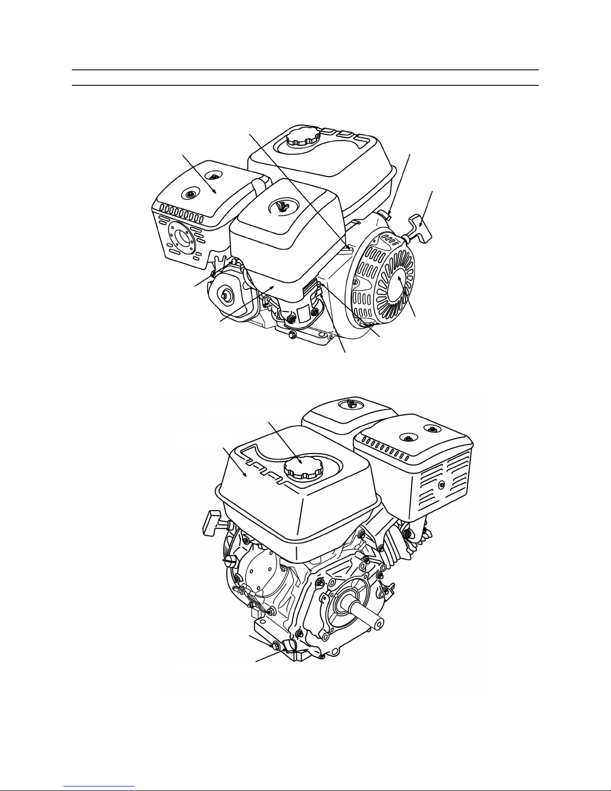
COMPONENTS & CONTROL LOCATIONS
2.
COMPONENTS & CONTROL LOCATIONS
THROTTLE LEVER
MUFFLER
SPARK PLUG
AIR CLEANER
FUEL VALVE LEVER
CHOKE LEVER
RECOIL STARTER
STARTER GRIP
IGNITION SWITCH
FUEL FILLER CAP
FUEL TANK
OIL DRAIN PLUG
OIL FILLER CAP/DIPSTICK
ENGINE DIAGRAM
Page 11SKU 65075 For technical questions, please call 1-800-444-3353.
Page 12
Remove the Oil Filler Cap2.
If the oil level is low, add the appropri-3.
ate type of oil until the oil level is at
the top lip.
Oil type:
32° F or above = SAE 10W-30
Below 32° F = SAE 5W-30.
Replace the Oil Filler Cap.4.
The hydraulic system must be vented 6.
during operation or it may become
vacuum locked and stop working. To
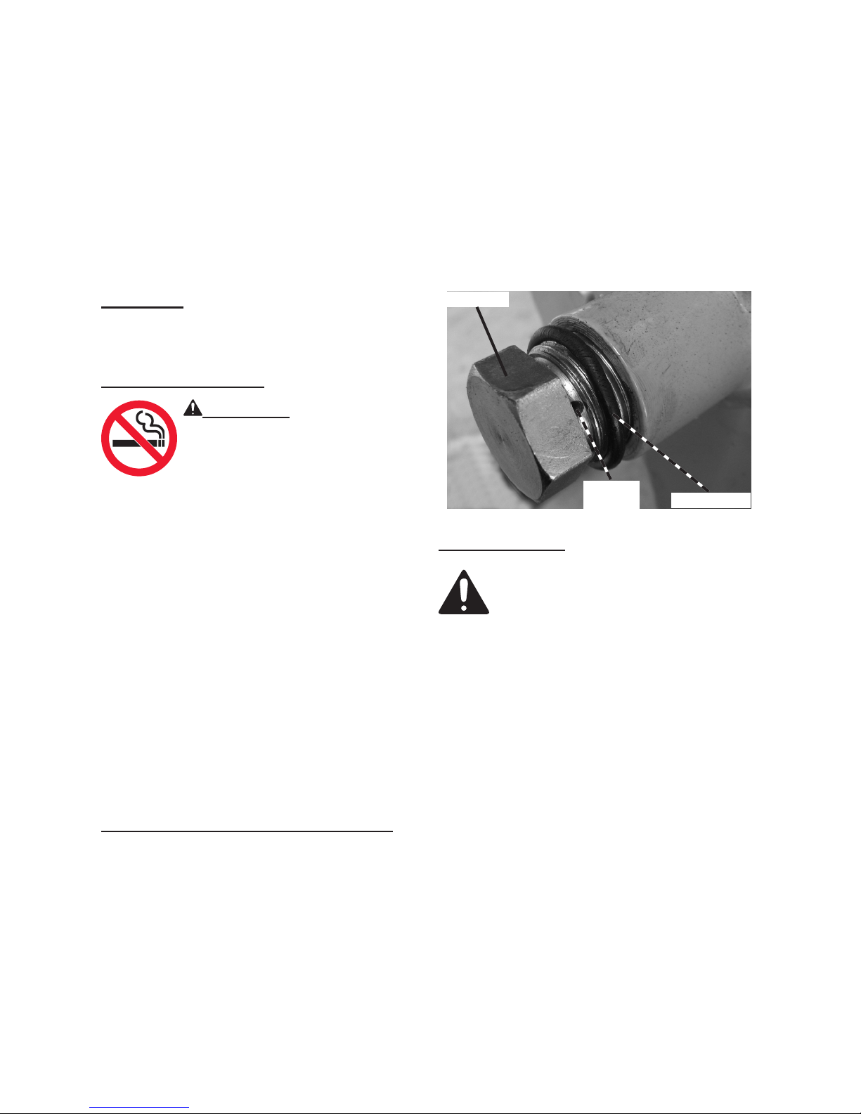
vent the system, back off oil ll plug
one turn (maximum). See Figure 3.
When the Log Splitter is not in operation or being transported, close the
air inlet hole by tightening the Plug,
as shown below.
CAUTION! Do not run the engine with too
little or too much oil. The engine will
be permanently damaged.
Checking Fuel Level
WARNING! To prevent re,
shut the engine off and wait
for it to cool before adding
fuel. Do not smoke.
Clean the Fuel Filler Cap and the 1.
area around it.
To Check the fuel level, unscrew and 1.
remove the Fuel Filler Cap.
Mix fuel stabilizer (not included) with 2.
86 octane (or better) unleaded gasoline according to fuel stabilizer directions.
Fill the Fuel Tank to about 1 inch 3.
under the lip of the gasoline tank
with the stabilized unleaded gasoline
mixture.
Then replace the Fuel Filler Cap.4.
Plug (37)
Start Procedure
Before starting the engine:
Follow the Set Up Instruc-a.
tions to prepare the equipment.
Inspect the equipment and b.
engine.
Fill the engine with the prop-c.
er amount and type of both
fuel and oil.
Read the Equipment Opera-d.
tion section that follows.
Air Inlet
Hole
O-ring (21)
Checking and Filling Hydraulic Fluid
Remove the Plug (37) and ll the tank 5.
with Hydraulic uid (not included).
To check the uid level remove the
Dipstick (62), check the level then
replace it. The uid should be at the
upper notch of the Dipstick. Be sure
that a constant oil level of 2.5 gallons
is maintained.
Turn the fuel valve lever to its 1.
“OPEN” position.
Turn the ignition switch to its ON or 2.
RUN position.
Then, turn the engine choke lever to 3.
its “CHOKE” position. Set the choke
lever in the “RUN” position when
starting a warm engine.
Page 12SKU 65075 For technical questions, please call 1-800-444-3353.
Page 13
Grasp the starter handle, and pull 4.
slowly until resistance is felt. While
holding the handle, allow the starter
rope to rewind slowly. Then, pull the
starter handle with a rapid, full arm
stroke. Once again while holding
the handle, allow the rope to rewind
slowly. Repeat as necessary, until
the engine starts.
After the engine starts and warms 5.
up, slowly move the choke lever to its
“RUN” position.
IMPORTANT: Allow the engine to 6.
run at no load for ve minutes with no
load after each start-up so that the
engine can stabilize.
both wheels of the Log Splitter before
starting a job.
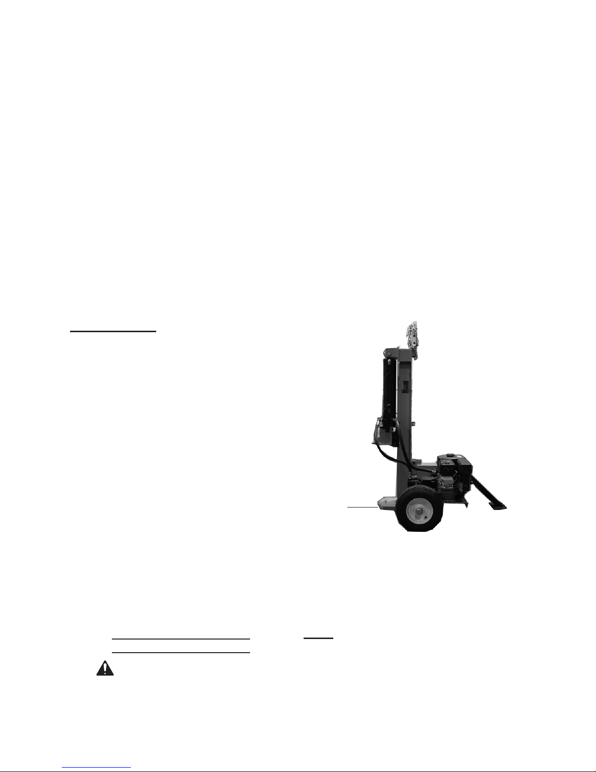
In FIGURE 1, the Rail Assembly is 2.
shown in Horizon tal mode for operation and travel. In FIGURE 4 the unit
is shown in the vertical position. To
change positions, remove the Hair
Pin Clip (29) and the Push Pin (26).
A close-up of this Push Pin (26) is
shown in FIGURE 3 on page 5. Tilt
the unit to the vertical position as
shown in FIGURE 4, and replace
both the Push Pin (26) and the Hair
Pin Clip (29) into the vertical posi tion
hole (See FIGURE 1). Reverse the
process to return to the horizontal
position.
Break-in Period
Breaking-in the engine will help to 1.
ensure proper equipment and engine
operation.
The operational break-in period will 2.
last about 3 hours of use. During this
period:
Do not apply a heavy load to the •
equipment.
Do not operate the engine at its •
maximum speed.
The maintenance break-in period will 3.
last about 20 hours of use. After this
period:
Change the engine oil.•
Under normal operating conditions
subsequent maintenance follows the
schedule explained in the MAINTENANCE AND SERVICING section.
Equipment Operation
1. WARNING! To avoid death or
serious injury; block each side of
FIGURE 4
Vertical Position
Place
Log
Here
Base
Start the Engine, following the steps 3.
listed in the “Start Procedure” section of this manual.
Place a log, no more than 25” long 4.
and 8” diameter, on the splitter base.
Note: Maximum diameter of the wood that
can be split may vary depending on
the density of the wood.
Page 13SKU 65075 For technical questions, please call 1-800-444-3353.
Page 14

Move the Directional Valve (58) into 5.
the lower position; moving the Slide
Assembly (3) to split the log.
Note: This Log Splitter is not road legal
and should not be conveyed on public roads.
To stop the advance of the Slide As-6.
sembly at any time, move the Directional Valve to the middle position.
Once the log is split, move the Direc-7.
tional Valve to its upper position to
back the wedge off the log and remove the split pieces.
Continue as detailed above until all 8.
logs are split.
To prevent accidents, turn off the en-9.
gine and after the engine has cooled,
disconnect its spark plug wire after
use. Drain all water out of the unit.
Clean external parts with clean cloth,
then store the equipment out of children’s reach according to the Storage
instructions in this manual.
Transporting the Log Splitter
WARNING!
IMPORTANT INFORMATION
This trailer’s Hitch Coupler MUST
be properly secured to the hitch ball of
the towing vehicle. After assembly and
attachment, pull up and down on the Hitch
Coupler to make sure the hitch ball is tting
snugly in the Hitch Coupler. There must
be no play between the hitch ball and
Hitch Coupler. If there is play, tighten the
Adjustment Nut until no play is present. If
the Adjustment Nut is too tight, the Handle
will not lock. Carefully read and follow
the complete instructions in this manual
BEFORE setup or use.
If the Coupler is not secured properly,
the ball could come loose while the trailer
is in motion, possibly causing property
damage, SERIOUS PERSONAL INJURY,
or DEATH.
When transporting the Log Splitter, •
make sure your hitch (not included)
is compatible with the Hitch Coupler
(9).
Follow all of the safety warn ings for •
towing in the vehicle’s manual.
Use the Safety Chain with Hook (4) •
when towing.
Do not tow the Log Splitter at •
speeds above 40 MPH.
Travel with the Front Leg Assembly •
and Rail Assembly in the horizontal
position.
Cover the air inlet hole on the Plug •
during transport.
Pull up and down on the Hitch Cou-10.
pler to make sure the hitch ball is
tting snugly in the Hitch Coupler.
There should be no play between the
hitch ball and Hitch Coupler. If there
is play, tighten the Adjustment Nut
until no play is present. If the Adjustment Nut is too tight, the Handle will
not lock.
Page 14SKU 65075 For technical questions, please call 1-800-444-3353.
Page 15
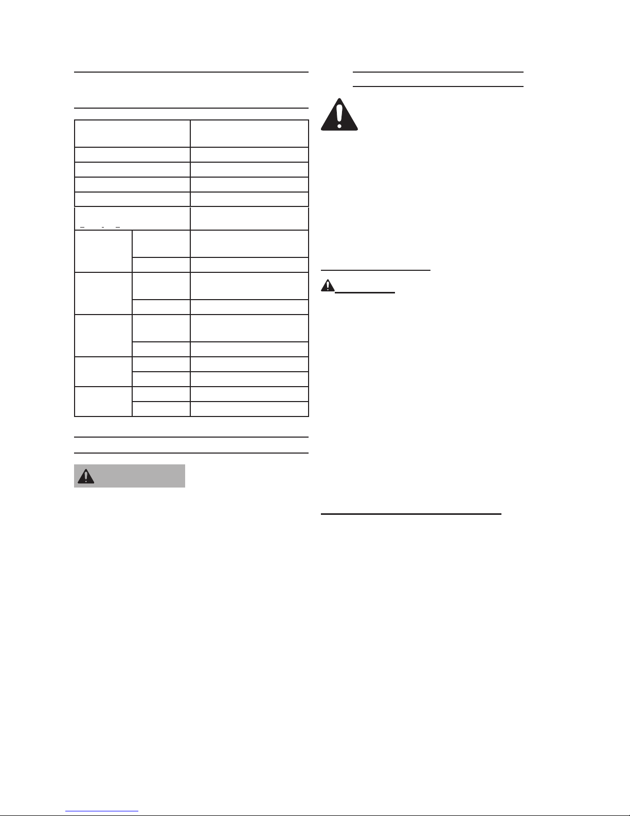
TECHNICAL
Maintenance Procedures
SPECIFICATIONS
Engine Type
Battery Required 12V 18Ah
Bore x Stroke 68mm x 54mm
Displacement 196cc
Compression Ratio 8.5:1
Rotation viewed from PTO
(power takeoff - the output shaft)
Fuel
Engine Oil
Spark Plug
Valve
Clearance
Speed
Type
Capacity 0.95 Gallons
Type SAE
Capacity 0.63 Quarts
Type
Gap 0.028 - 0.031”
Intake 0.15 ± 0.02 mm
Exhaust 0.20 ± 0.02 mm
Idle 1,400 ± 150 RPM
Maximum 3,400 RPM
Single Cylinder 4 stroke
OHV
Counterclockwise
86+ octane unleaded
gasoline
10W30 above 32° F
5W30 at 32° F or below
F7RTC or
NGK F7TC
Many maintenance procedures,
including any not detailed
in this manual, will need to
be performed by a qualied
technician for safety. If you
have any doubts about your
ability to safely service the
equipment or engine, have a
qualied technician service the
equipment instead.
Engine Oil Change
CAUTION! Oil is very hot during opera-
tion and can cause burns. Wait for
engine to cool before changing oil.
Place a drain pan (not included) un-1.
derneath the crankcase’s drain plug.
Remove the drain plug and, if pos-2.
sible, tilt the crankcase slightly to help
drain the oil out. Recycle used oil.
SERVICING
Risk of serious
WARNING
from accidental starting. Turn
the Power Switch of the
equipment to its “OFF”
position, wait for the engine to
cool, and unplug the spark
plug wire(s) before performing
any inspection, maintenance,
or cleaning procedures.
Damaged equipment can fail,
causing serious personal
injury. Do not use damaged
equipment. If abnormal noise,
vibration, or excess smoking
occurs, have the problem
corrected before further use.
personal injury
Replace the drain plug and tighten it.3.
Rell the oil to the proper level follow-4.
ing the instructions under the Starting
the Engine section.
Air Filter Element Maintenance
The air cleaner cover is held in place 1.
by a wing nut or clamps. Remove it.
Remove the air lter element.2.
Cleaning:3.
For “paper” lter elements: a.
To prevent injury from dust and
debris, wear ANSI-approved safety
goggles, NIOSH-approved dust
mask/respirator, and heavy-duty
work gloves. In a well-ventilated
area away from bystanders, use
pressurized air to blow dust out of
the air lter.
Page 15SKU 65075 For technical questions, please call 1-800-444-3353.
Page 16

If this does not get the lter reasonably clean, replace it.
For foam lter elements: b.
Wash the element in warm water
and mild detergent several times.
Rinse. Squeeze out excess water
and allow it to dry completely. Soak
the lter in lightweight oil briey, then
squeeze out the excess oil.
Install the new lter or the cleaned 4.
lter. Secure the Air Cleaner Cover
before use.
Spark Plug Maintenance
Disconnect spark plug wire from 1.
end of plug. Clean out debris from
around spark plug.
Apply dielectric spark plug boot 6.
protector (not included) to the end of
the spark plug and reattach the wire
securely.
Fuel Filter Replacement (if equipped)
WARNING! RISK OF FIRE
OR EXPLOSION. Replace the
fuel lter in a well-ventilated
area away from ignition sources. Do not smoke.
Wait for engine to cool completely 1.
before proceeding.
Wear protective gear including, ANSI-2.
approved safety goggles, NIOSHapproved dust mask/respirator, and
nitrile gloves.
Using a spark plug wrench, remove 2.
the spark plug.
Inspect the spark plug: 3.
If the electrode is oily, clean it using a
clean, dry rag.
If the electrode has deposits on it,
polish it using emery paper.
If the white insulator is cracked or
chipped, the spark plug needs to be
replaced.
When installing a new spark plug, ad-4.
just the plug’s gap to the specication
on the Technical specication chart.
Do not pry against the electrode, the
spark plug can be damaged.
Install the new spark plug or the 5.
cleaned spark plug into the engine.
Gasket-style: Finger-tighten until the
gasket contacts the cylinder head,
then about 1/2-2/3 turn more.
Non-gasket-style: Finger-tighten until
the plug contacts the head, then
about 1/16 turn more.
Close fuel valve leading from gas 3.
tank completely.
Take note of the fuel lter’s orienta-4.
tion.
Place a suitable container under the 5.
fuel lter.
Disconnect the fuel lines leading to 6.
and from the fuel lter and allow fuel
to drain onto the container.
Install new fuel lter in the same 7.
orientation. Make sure to properly
secure both fuel lines.
Clean up and properly dispose of all 8.
fuel.
Wait for at least one hour before use 9.
to allow all residual fuel vapors to
dissipate. To prevent FIRE, do not
start the engine while the smell of
fuel hangs in the air. Remember to
open the fuel valve before restarting
the engine. It may take a little longer
than usual to start the engine be-
Page 16SKU 65075 For technical questions, please call 1-800-444-3353.
Page 17

cause the fuel needs to rell the fuel
line and new lter.
After Every 300 Operation Hours:
Clean fuel tank and carburetor.a.
Cleaning, Maintenance, and
Lubrication Schedule
Note: This maintenance schedule is
intended solely as a general guide.
If performance decreases or if equipment operates unusually, check systems immediately. The maintenance
needs of each piece of equipment will
differ depending on factors such as
duty cycle, temperature, air quality,
fuel quality, and other factors.
Note: These procedures are in addition to
the regular checks and maintenance
explained as part of the regular operation of the engine and equipment.
After 20 Operation Hour Break-in
Period:
Change engine oil.a.
After Every 25 Operation Hours:
Clean/replace air lter element.a.
Inspect/clean spark plug.b.
Blow out water lters.c.
After Every 50 Operation Hours:
Change engine oil.a.
Replace fuel lter (if equipped).b.
After Every 100 Operation Hours:
Replace spark plug.a.
Replace air lter element.b.
Clean carbon build-up from combus-b.
tion chamber.
Storage
Wait for engine to cool, then clean 1.
engine with clean cloth.
When the equipment is to remain idle 2.
for longer than 20 days, prepare the
engine for storage as follows:
Change engine oil and empty fuel a.
tank.
Either leave fuel tank empty or b.
rell fuel tank with fresh unleaded
gasoline mixed with a fuel stabilizer
intended for long term engine stor-
age (not included). After lling, run
engine for about 5-10 minutes to circulate the treated gasoline through
the carburetor. Wait for engine to
cool before proceeding.
Clean out area around spark plug. c.
Remove spark plug and pour one
tablespoon of engine oil into cylinder
through spark plug hole.
Replace spark plug, but leave spark d.
plug wire disconnected.
Pull recoil starter to distribute oil in e.
cylinder. Stop after one or two revolutions when you feel the piston start
the compression stroke (when you
start to feel resistance).
Disconnect battery cables (if f.
equipped).
Note: All maintenance procedures sched-
uled for 25, 50, and 100 operation
hours should be performed at least
yearly.
Apply a thin coat of rust preventive oil 3.
to all metal parts.
Cover and store in a dry, well-ventilat-4.
ed area out of reach of children.
Page 17SKU 65075 For technical questions, please call 1-800-444-3353.
Page 18

Before starting the engine after stor-5.
age, keep in mind that untreated gasoline will deteriorate quickly. Drain
the fuel tank and change to fresh fuel
if untreated gasoline has been sitting
for a month, if treated gasoline has
been sitting beyond the fuel stabilizer’s recommended time period, or if
the engine does not start properly.
Transport Maintenance
Remove the spark plug from the 3.
engine (see engine manual) to keep
the engine from starting during this
process.
Push the Directional Valve (58) for-4.
ward, toward the front of the Cylinder
(1) (see FIGURE 1).
Pull the engine starter cord 10-15 5.
times until the hydraulic cylinder piston moves forward.
BEFORE1. transport, check the Tires
for wear and proper ination (60 PSI).
Prior to Transport and at 500 MILE in-2.
tervals during trips, check and tighten
the Tire Lug Nuts. Torque from 85 to
90 ft-lb.
EVERY 2,000 TO 3,000 MILES3. of
Travel, lubricate the Hub Assemblies
with a heavy weight bearing grease.
Follow the Bearing Packing Instructions. After each Hub Assembly is
reassembled, tighten the Castle Nut
until the wheel starts spinning with
slight resistance. Loosen the Castle
Nut about 1/2turn from this point.
Insert a new Cotter Pin through the
Castle Nut and the hole in the axle.
Bend the Pin back, locking it and the
Nut in place.
CAUTION: Keep everything away from the
splitting edge during this process.
Tighten the Oil Plug (37).6.
Replace the spark plug.7.
Test the Log Splitter to make sure it is 8.
operating properly. If not, repeat the
above process.
Bleeding the Hydraulic System
If the Log Splitter begins to lose pow-1.
er or splitting efciency, it may be a
result of air becoming trapped in the
hydraulic system. Follow the steps
below to bleed air from the system.
Loosen the Oil Plug (37) and make 2.
sure the O-ring is out of the way to
expose the air hole in the Oil Plug
(37).
Page 18SKU 65075 For technical questions, please call 1-800-444-3353.
Page 19

Troubleshooting
Problem Possible Causes Probable Solutions
Engine will not start FUEL RELATED:
No fuel in tank or fuel valve closed.1.
Choke not in start position, 2.
especially with cold engine.
Low quality or deteriorated, old 3.
gasoline.
Carburetor not primed. 4.
Dirty fuel passageways blocking 5.
fuel ow.
Carburetor needle stuck. Fuel can 6.
be smelled in the air.
Too much fuel in chamber. This can 7.
be caused by the carburetor needle
sticking.
IGNITION (SPARK) RELATED:
Spark plug wire not connected 1.
securely.
Spark plug electrode wet or dirty.2.
Incorrect spark plug gap.3.
Spark plug wire broken.4.
Incorrect spark timing or faulty 5.
ignition system.
COMPRESSION RELATED:
Cylinder not lubricated. Problem 1.
after long storage periods.
Loose or broken spark plug. 2.
(Hissing noise will occur when
trying to start.)
Loose cylinder head or damaged 3.
head gasket. (Hissing noise will
occur when trying to start.)
Engine valves or tappets 4.
misadjusted or stuck.
FUEL RELATED:
Fill fuel tank and open fuel valve.1.
Move choke to start position if 2.
engine is cold.
Use only fresh 86+ octane 3.
unleaded gasoline.
Prime carburetor by pressing 4.
priming bulb specied number of
times (if equipped).
Clean out passageways using 5.
fuel additive. Heavy deposits may
require further cleaning.
Gently6. tap side of carburetor oat
chamber with screwdriver handle.
Turn choke to run position. 7.
Remove spark plug and pull the
start handle several times to air out
the chamber. Reinstall spark plug
and set choke to start position.
IGNITION (SPARK) RELATED:
Connect spark plug wire properly. 1.
Clean spark plug.2.
Correct spark plug gap.3.
Replace spark plug wire.4.
Have qualied technician diagnose/5.
repair ignition system.
COMPRESSION RELATED:
Pour tablespoon of oil into spark 1.
plug hole. Crank engine a few
times and try to start again.
Tighten spark plug. If that does 2.
not work, replace spark plug. If
problem persists, may have head
gasket problem, see #3.
Tighten head. If that does not 3.
remedy problem, replace head
gasket.
Adjust valve clearance. If that does 4.
not work, clean or replace valves/
tappets.
Follow all safety precautions whenever diagnosing or servicing the
equipment or engine.
Page 19SKU 65075 For technical questions, please call 1-800-444-3353.
Page 20

Troubleshooting
Problem Possible Causes Probable Solutions
Engine misres Spark plug wire loose.1.
Engine stops
suddenly
Engine knocks Old or low quality gasoline. 1.
Engine backres Impure or low quality gasoline. 1.
Does not produce
high pressure
Incorrect spark plug gap or 2.
damaged spark plug.
Defective spark plug wire.3.
Old or low quality gasoline. 4.
Incorrect compression.5.
Low oil shutdown. 1.
Fuel tank empty or full of impure or 2.
low quality gasoline.
Defective fuel tank cap creating 3.
vacuum, preventing proper fuel
ow.
Faulty magneto.4.
Engine overloaded. 2.
Incorrect spark timing, deposit 3.
buildup, worn engine, or other
mechanical problems.
Engine too cold. 2.
Intake valve stuck or overheated 3.
engine.
Diameter of water supply hose too 1.
small
Water supply is restricted. 2.
Not enough water supply.3.
Check wire connections.1.
Re-gap or replace spark plug. 2.
Replace spark plug wire.3.
Use only fresh 86+ octane 4.
unleaded gasoline.
Diagnose and repair compression. 5.
(Use Engine will not start:
COMPRESSION RELATED
section.)
Fill engine oil to proper level. 1.
Check engine oil before EVERY
use.
Fill fuel tank with fresh 86+ octane 2.
unleaded gasoline.
Test/replace fuel tank cap. 3.
Have qualied technician service 4.
magneto.
Fill fuel tank with fresh 86+ octane 1.
unleaded gasoline.
Do not exceed equipment’s load 2.
rating.
Have qualied technician diagnose 3.
and service engine.
Fill fuel tank with fresh 86+ octane 1.
unleaded gasoline.
Use cold weather fuel and oil 2.
additives to prevent backring.
Have qualied technician diagnose 3.
and service engine.
Replace hose with a ¾ inch hose. 1.
Check water supply hose for kinks, 2.
leaks, or blockage.
Open water faucet all the way.3.
Follow all safety precautions whenever diagnosing or servicing the
equipment or engine.
Page 20SKU 65075 For technical questions, please call 1-800-444-3353.
Page 21

Troubleshooting
Problem Possible Causes Probable Solutions
Output pressure
varies
No intake of
chemicals.
Follow all safety precautions whenever diagnosing or servicing the
equipment or engine.
Not enough water supply. 1.
Water inlet screen is clogged.2.
Nozzle is clogged.3.
Nozzle has mineral build up.4.
Chemical hose not properly 1.
inserted into unit.
Tube cracked or split.2.
Wrong Nozzle.3.
Injector turned off.4.
Injection tube strainer clogged.5.
Nozzle blocked. 6.
Dried chemicals in injector.7.
Check water supply hose for kinks, 1.
leaks, or blockage. Open faucet all
the way.
Remove inlet screen and rinse out.2.
Remove Nozzle and clean.3.
Remove Nozzle and clean with 4.
vinegar.
Push rmly into injector. Replace 1.
tube.
Switch to black Nozzle.2.
Turn collar counterclockwise.3.
Clean strainer.4.
Clean Nozzle.5.
Dissolve by running warm water 6.
through the injection tube.
Run clean water through injector 7.
until clear.
PLEASE READ THE FOLLOWING CAREFULLY
THE MANUFACTURER AND/OR DISTRIBUTOR HAS PROVIDED THE PARTS LIST AND ASSEMBLY
DIAGRAM IN THIS MANUAL AS A REFERENCE TOOL ONLY. NEITHER THE MANUFACTURER OR
DISTRIBUTOR MAKES ANY REPRESENTATION OR WARRANTY OF ANY KIND TO THE BUYER THAT
HE OR SHE IS QUALIFIED TO MAKE ANY REPAIRS TO THE PRODUCT, OR THAT HE OR SHE IS
QUALIFIED TO REPLACE ANY PARTS OF THE PRODUCT. IN FACT, THE MANUFACTURER AND/
OR DISTRIBUTOR EXPRESSLY STATES THAT ALL REPAIRS AND PARTS REPLACEMENTS SHOULD
BE UNDERTAKEN BY CERTIFIED AND LICENSED TECHNICIANS, AND NOT BY THE BUYER. THE
BUYER ASSUMES ALL RISK AND LIABILITY ARISING OUT OF HIS OR HER REPAIRS TO THE
ORIGINAL PRODUCT OR REPLACEMENT PARTS THERETO, OR ARISING OUT OF HIS OR HER
INSTALLATION OF REPLACEMENT PARTS THERETO.
Page 21SKU 65075 For technical questions, please call 1-800-444-3353.
Page 22

GENERAL PARTS LIST
Part Description Qty.
1 Cylinder 1
2 Rail Assembly 1
3 Slide Assembly 1
4 Safety Chain With Hook 1
5 Slide Guide 2
6 Slide Retainer 2
7 Bolt 1/2’’*2-1/2’’ 6
8 Hex Nut 1/2’’ 7
9 Hitch Coupler 1
10 Oil Tank Assembly 1
11 Front Leg Assembly 1
12 Hex Bolt 1/2’’*1-3/4’’ 2
13 Hex Nut 1/2’’ 2
14 Hex Nut 3/8’’ 3
15 Washer 1/2’’ 2
16 Hex Bolt 9/16’’*1-1/4’’ 2
17 Hex Nut 9/16’’ 2
18 Washer 1
19 Hex Bolt 5/16’’*2-3/4’’ 1
20 Hex Nut 3/8’’ 1
21 O-ring Seal 1
22 Hex Bolt 1/2’’*1-3/4’’ 4
23 Hex Nut 5/16’’ 4
24 Spring Washer 5/16’’ 8
25 Cotter Pin 2
26 Push Pin 2
27 Clevis Pin 1
28 Hair Pin Clip 2
29 Hair Pin Clip 2.5’’ 2
30 Slide Holder 1
31 Hydraulic Tubing 1
Part Description Qty.
32 High Pressure Hose 1
33 Return Hose 1
34 Inlet Hose 1
35 Hose Clamp 4
36 Male Connector 1
37 Oil Plug 1
38 High Pressure Fitting 1
39 90° Elbow Fitting #2 2
40 90° Elbow Fitting #3 2
41 Hex Bolt 3/8’’*3/4’’ 1
42 Hex Bolt 5/16’’*1’’ 4
43 Oil Filter 1
44 Pump Mounting Bracket 1
45 Pump 1
46 Hex Bolt 5/16’’*1’’ 4
47 Hex Bolt 3/8’’*3-1/4’’ 2
48 Tire 2
49 Bearing 30205E 4
50 Washer 3/4’’ 2
51 Spindle Nut 2
52 Coupling -Pump Side 1
53 Coupling -Engine Side 1
54 Pump Key 1/8’’ 1
55 Engine Key 1
56 Hex Screw 2
57 Engine 1
58 Directional Valve 1
59 Seal 2
60 Hex Bolt 3/8’’*3-1/2’’ 1
61 Wheel Cap 2
62 Dipstick 1
Record Product’s Serial Number Here:
Note: If product has no serial number, record month and year of purchase instead.
Note: Some parts are listed and shown for illustration purposes only, and are not avail-
able individually as replacement parts.
Page 22SKU 65075 For technical questions, please call 1-800-444-3353.
Page 23
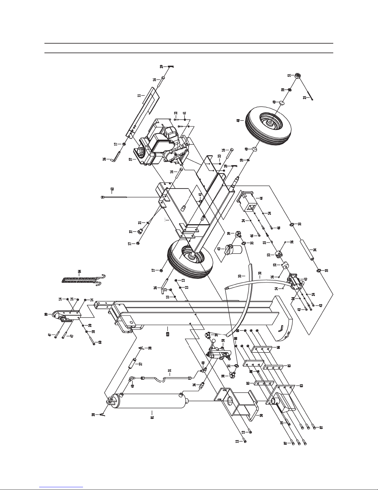
GENERAL ASSEMBLY DIAGRAM
10
Page 23SKU 65075 For technical questions, please call 1-800-444-3353.
Page 24
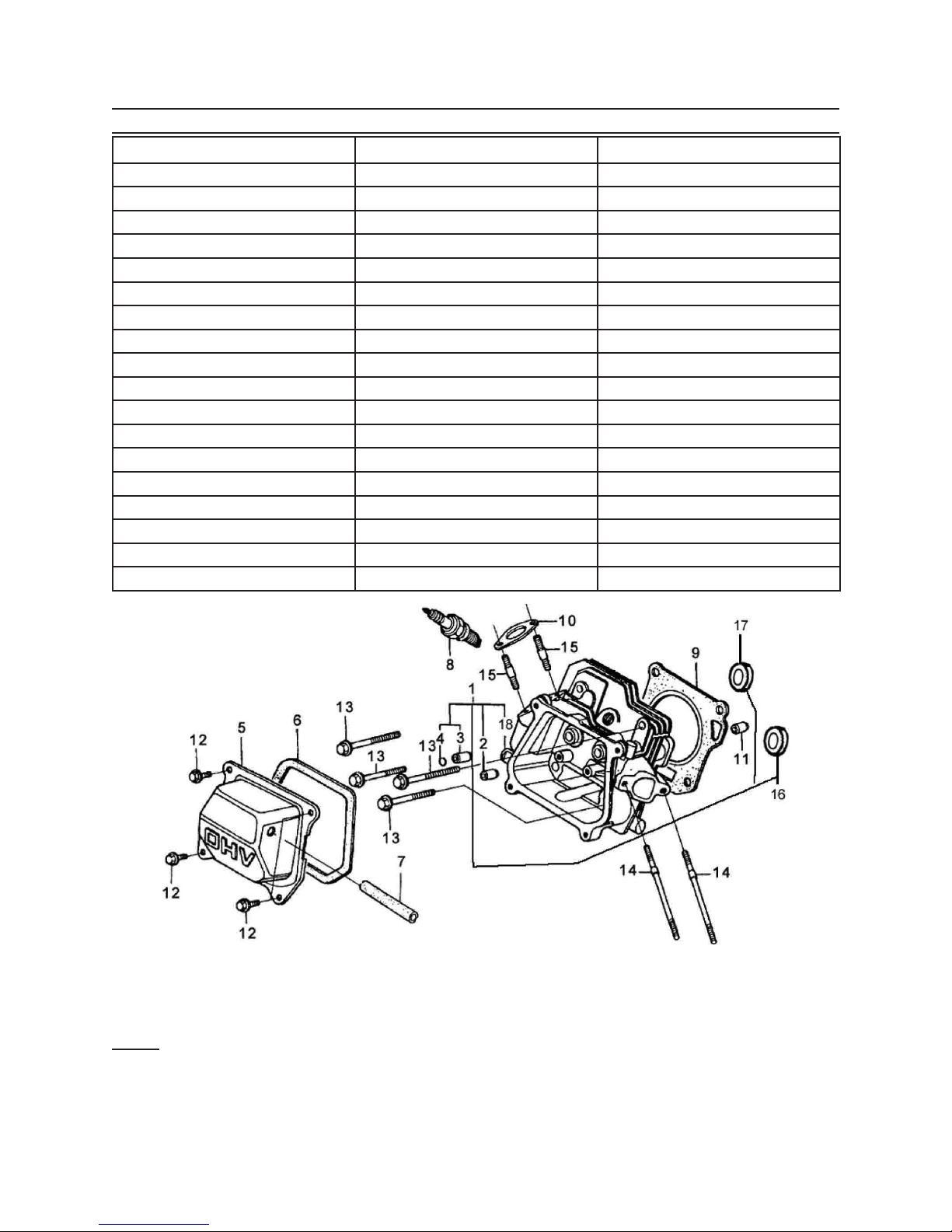
CYLINDER HEAD PARTS LIST & DIAGRAM
Part # Description Qty
1B Cylinder Head Assembly 1
2B Intake Valve Guide 1
3B Exhaust Valve Guide 1
4B Valve Guide Clip 1
5B Cover 1
6B Packing 1
7B Breathing Tube 1
8B Spark Plug 1
9B Cylinder Gasket 1
10B Mufer Gasket 1
11B Pin 2
12B Bolt 6x14 4
13B Bolt 8x55 4
14B Intake Bolt 2
15B Exhaust Bolt 2
16B Intake Valve Seat 1
17B Exhaust Valve Seat 1
18B Cylinder Head 1
When ordering parts for this component be sure to use the correct sufx.
Note: Some parts are listed and shown for illustration purposes only, and are not avail-
able individually as replacement parts.
Page 24SKU 65075 For technical questions, please call 1-800-444-3353.
Page 25
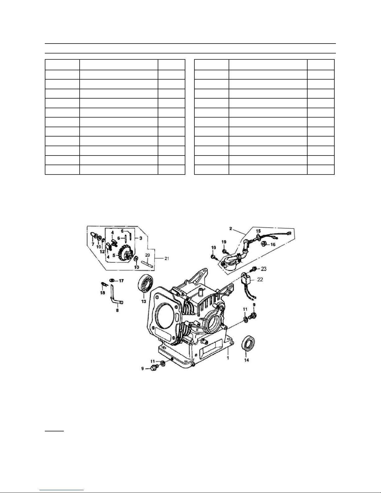
CRANK CASE PARTS LIST & DIAGRAM
Part # Description Qty
1C Crank Case Assembly 1
2C Oil Level Switch 1
3C Governor Gear Assembly 1
4C Weight 2
5C Governor Gear 1
6C Weight Pin 2
7C Slider 1
8C Shaft Arm 1
9C Drain Plug Bolt 2
10C Washer 2
11C Washer 2
Part # Description Qty
12C Clip 1
13C Ball Bearing 1
14C Oil Seal 1
15C O-ring 1
16C Nut 1
17C Washer 1
18C R-pin 1
19C Bolt 6x12 3
20C Shaft 1
21C Governor Assembly 1
22C Oil Alarm 1
When ordering parts for this component be sure to use the correct sufx.
Note: Some parts are listed and shown for illustration purposes only, and are not avail-
able individually as replacement parts.
Page 25SKU 65075 For technical questions, please call 1-800-444-3353.
Page 26
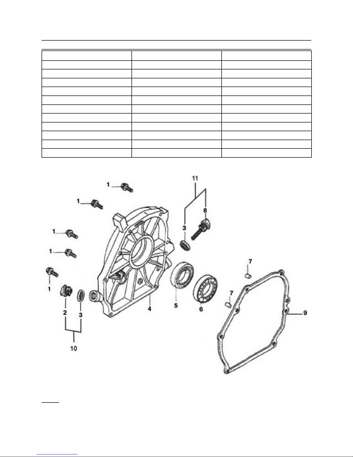
CRANK CASE COVER PARTS LIST AND DIAGRAM
Part # Description Qty
1D Bolt 6
2D Oil Stick 1
3D Packing 2
4D Cover 1
5D Oil Seal 1
6D Bearing 1
7D Pin 2
8D Oil Filler Cap 1
9D Packing Case Cover 1
10D Oil Fill Assembly 1
11D Cap Assembly 1
When ordering parts for this component be sure to use the correct sufx.
Note: Some parts are listed and shown for illustration purposes only, and are not avail-
able individually as replacement parts.
Page 26SKU 65075 For technical questions, please call 1-800-444-3353.
Page 27
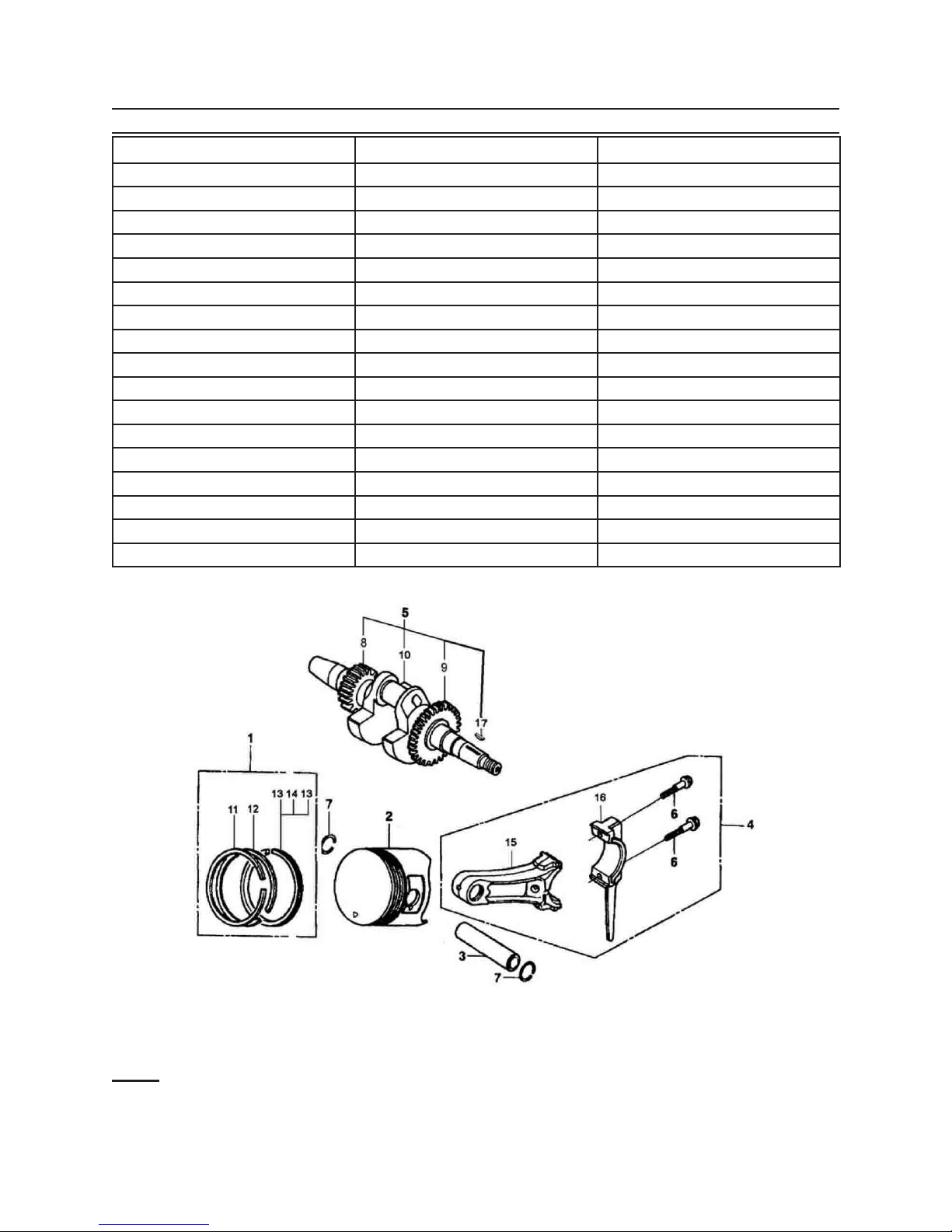
CRANKSHAFT/PISTON PARTS LIST & DIAGRAM
Part # Description Qty
1E Ring Set 1
2E Piston 1
3E Pin 1
4E Rod Assembly 1
5E Crankshaft Assembly 1
6E Bolt 2
7E Clip 2
8E Timing Gear 1
9E Gear 1
10E Crankshaft 1
11E First Ring 1
12E Second Ring 1
13E Oil Ring 2
14E Bushing Ring 1
15E Connecting Rod 1
16E Connecting Rod Cover 1
17E Key 1
When ordering parts for this component be sure to use the correct sufx.
Note: Some parts are listed and shown for illustration purposes only, and are not avail-
able individually as replacement parts.
Page 27SKU 65075 For technical questions, please call 1-800-444-3353.
Page 28
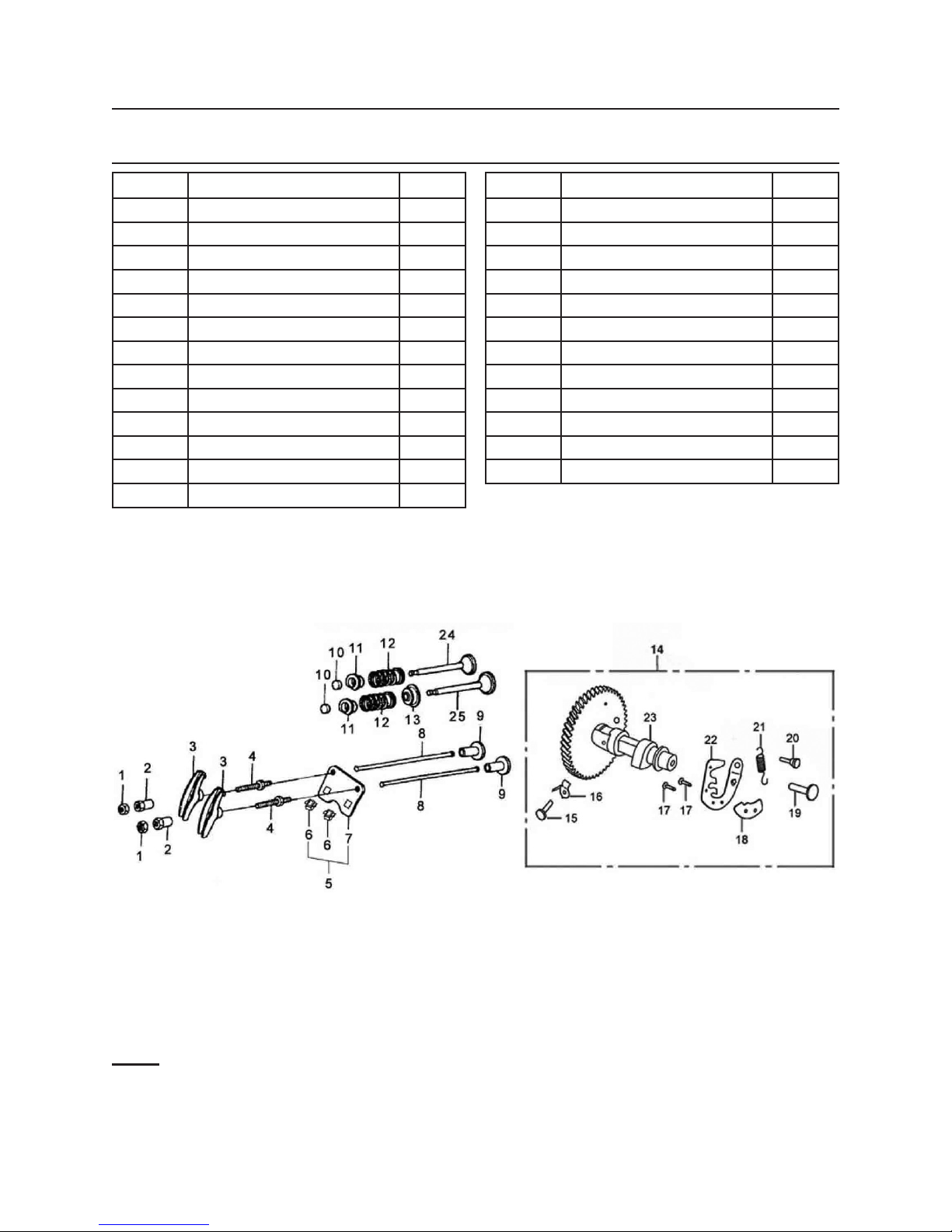
GAS DISTRIBUTION ADJUSTMENT SYSTEM PARTS LIST &
DIAGRAM
Part # Description Qty
1F Nut 2
2F Rocker Arm 2
3F Valve Rocker 2
4F Pivot Bolt 2
5F Plate Assembly 1
6F Block Guide 2
7F Push Rod Guide 1
8F Push Rod 2
9F Valve Lifter 2
10F Rotator Valve 2
11F Valve Spring Retainer 2
12F Valve Spring 2
13F Guide Seal 1
Part # Description Qty
14F Camshaft Assembly 1
15F Reducer Pin 1
16F Reducer 1
17F Matching Block Pin 2
18F Matching Block 1
19F Flying Block Pin 1
20F Spring Pin 1
21F Flying Block Spring 1
22F Flying Block 1
23F Camshaft 1
24F Exhaust Valve 1
25F Intake Valve 1
When ordering parts for this component be sure to use the correct sufx.
Note: Some parts are listed and shown for illustration purposes only, and are not avail-
able individually as replacement parts.
Page 28SKU 65075 For technical questions, please call 1-800-444-3353.
Page 29
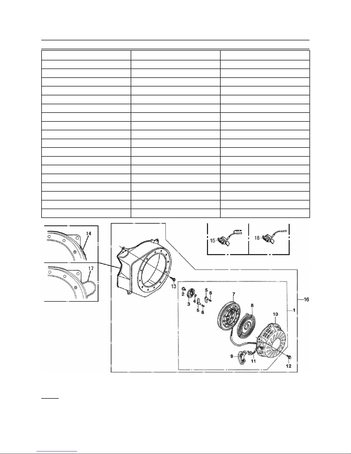
STARTER SUBASSEMBLY PARTS LIST & DIAGRAM
Part # Description Qty
1G Starter Assembly 1
2G Set Screw 1
3G Ratchet Guide 1
4G Friction Spring 1
5G Starter Ratchet 2
6G Return Spring 2
7G Recoil Starter Reel 1
8G Recoil Starter Spring 1
9G Recoil Starter Knob 1
10G Fan Cover 1
11G Rope 1
12G Bolt 6x8 3
13G Bolt 6x10 4
14G Fan Cover 1
15G Switch Assembly 1
16G Recoil Starter 1
17G Fan Cover 1
18G Stop Switch Assembly 1
When ordering parts for this component be sure to use the correct sufx.
Note: Some parts are listed and shown for illustration purposes only, and are not avail-
able individually as replacement parts.
Page 29SKU 65075 For technical questions, please call 1-800-444-3353.
Page 30
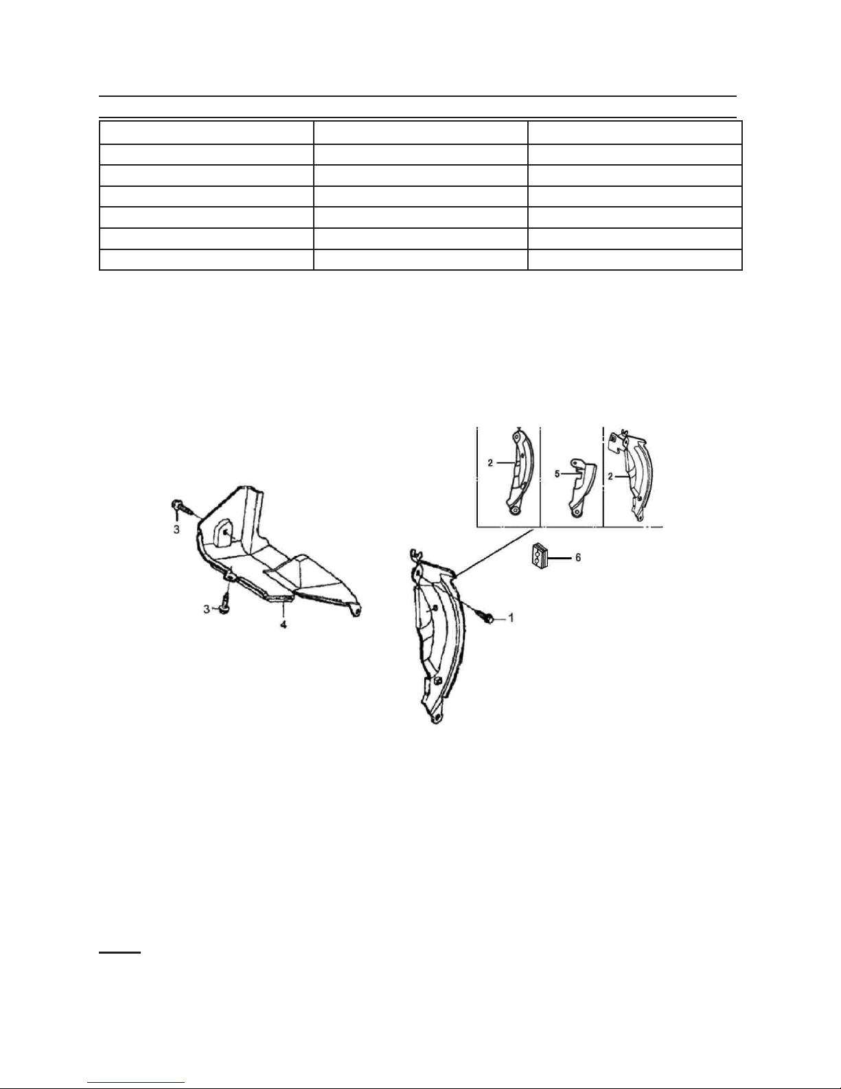
DIVERSION ASSEMBLY PARTS LIST & DIAGRAM
Part # Description Qty
1H Bolt 6x20 1
2H Side Plate 1
3H Bolt 6x8 2
4H Shroud 1
5H Side Plate 1
6H Grommet 1
When ordering parts for this component be sure to use the correct sufx.
Note: Some parts are listed and shown for illustration purposes only, and are not avail-
able individually as replacement parts.
Page 30SKU 65075 For technical questions, please call 1-800-444-3353.
Page 31
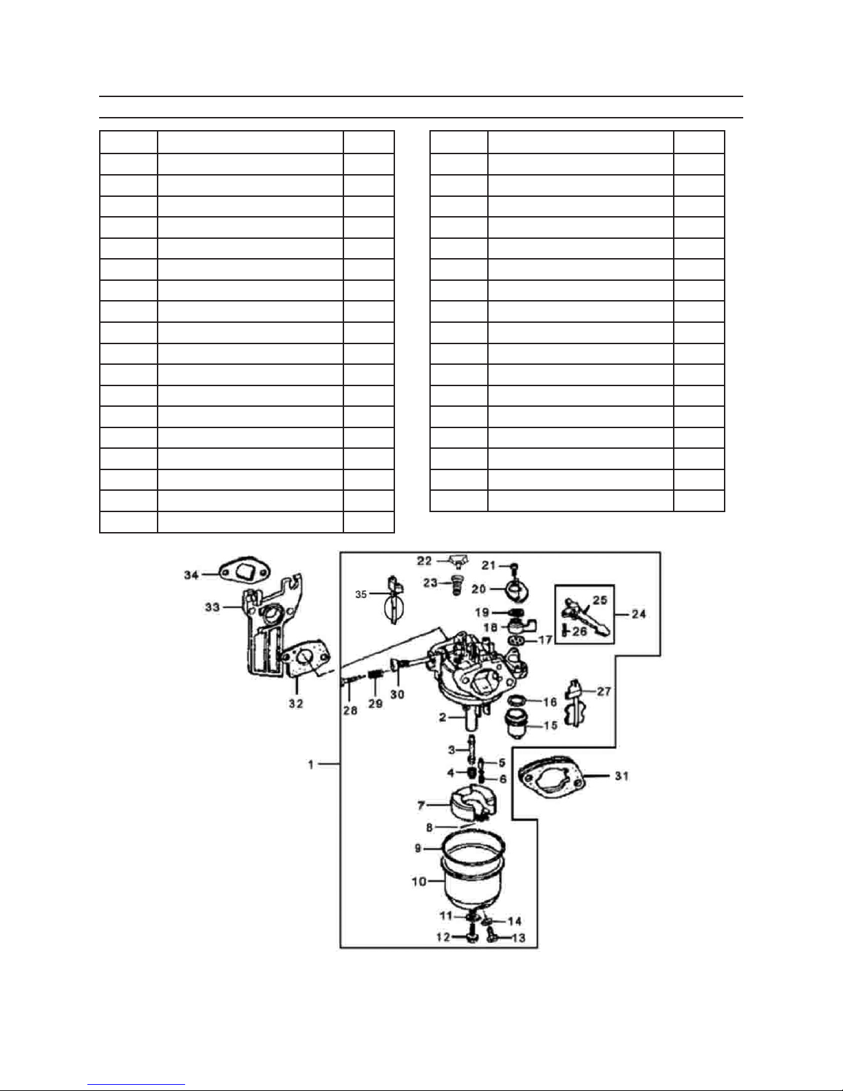
CARBURETOR PARTS LIST & DIAGRAM
Part # Description Qty
1J Carburetor Assembly 1
2J Carburetor 1
3J Main Nozzle 1
4J Main Jet 1
5J Float Valve 1
6J Valve Set Spring 1
7J Float 1
8J Float Pin 1
9J Oil Cup Gasket 1
10J Oil Cup 1
11J Gasket Bolt 1
12J Bolt 1
13J Drain Bolt 1
14J Drain Bolt Gasket 1
15J Fuel Strainer Cup 1
16J Fuel Strainer Cup Packing 1
17J Fuel Packing 1
18J Lever 1
Part # Description Qty
19J Lever Spring 1
20J Setting Plate 1
21J Screw 3x8 2
22J Jet Set 1
23J Pilot Jet Set 1
24J Choke Lever Assembly 1
25J Choke Lever 1
26J Choke Lever Pin 1
27J Choke Set 1
28J Screw 1
29J Screw Spring 1
30J Throttle Stop Screw 1
31J Air Cleaner 1
32J Carburetor Packing 1
33J Carburetor Insulation 1
34J Packing 1
35J Throttle Valve 1
When ordering parts for this component be sure to use the correct sufx.
Page 31SKU 65075 For technical questions, please call 1-800-444-3353.
Page 32
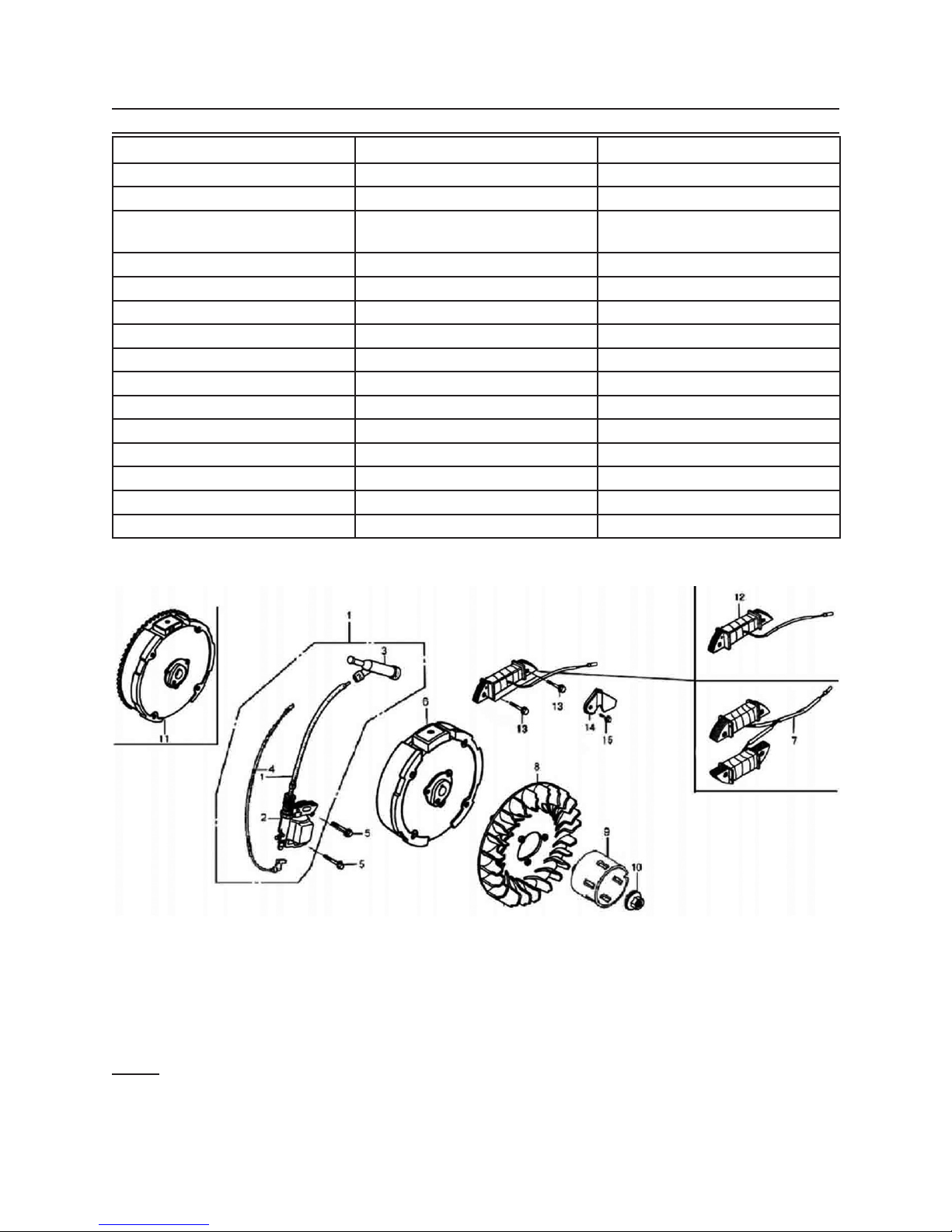
FLYWHEEL/COIL ASSEMBLY PARTS LIST & DIAGRAM
Part # Description Qty
1K Ignition Assembly 1
2K Ignition Coil 2
3K Noise Suppression Cap
Assembly
4K Stop Switch Cord 1
5K Bolt 6x30 2
6K Flywheel Cover 1
7K Charge Coil Assembly 1
8K Cooling Fan 1
9K Starter Pulley 1
10K Nut 1
11K Flywheel 1
12K Charge Coil 1
13K Bolt 6x35 2
14K Cord Clamp 1
15K Bolt 6x8 1
1
When ordering parts for this component be sure to use the correct sufx.
Note: Some parts are listed and shown for illustration purposes only, and are not avail-
able individually as replacement parts.
Page 32SKU 65075 For technical questions, please call 1-800-444-3353.
Page 33
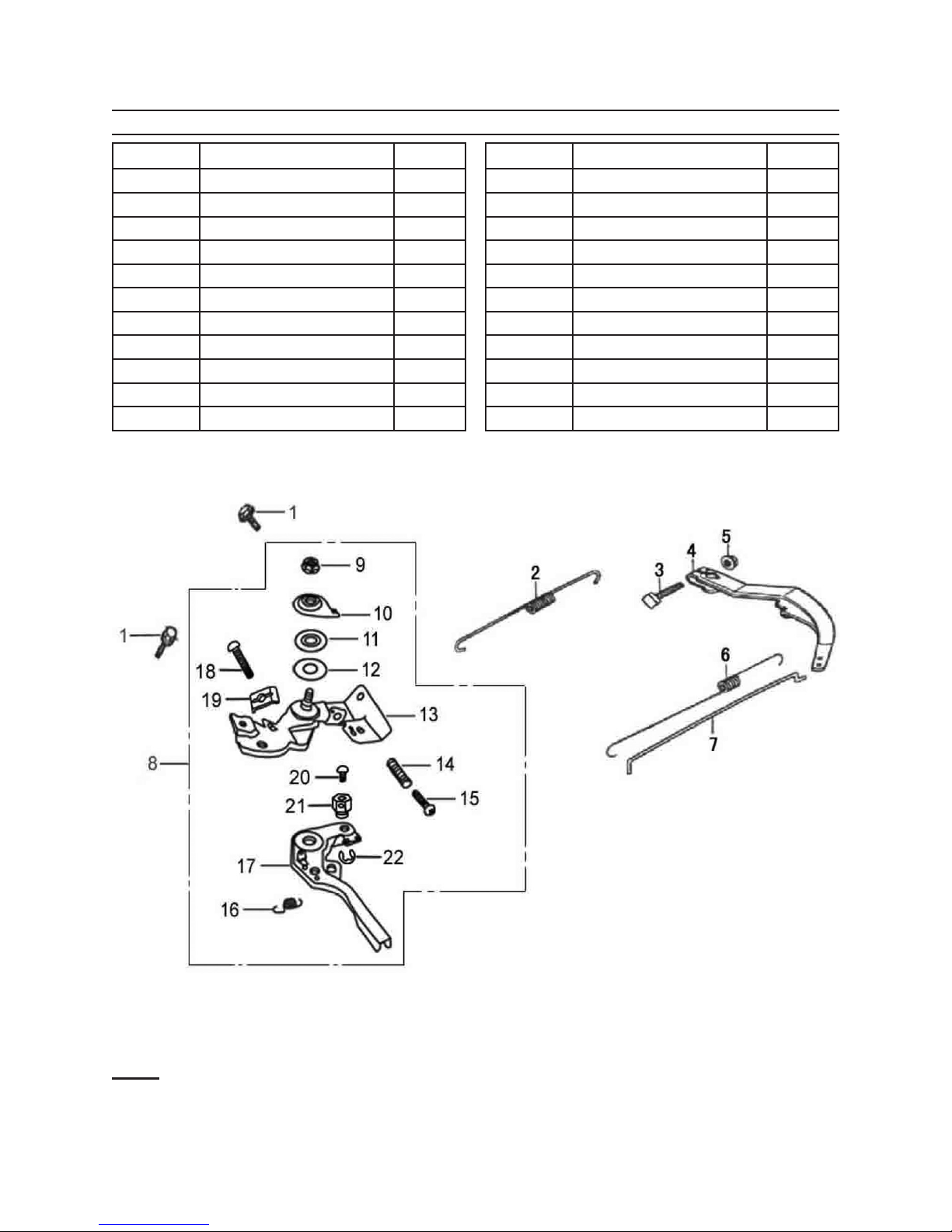
CONTROL SYSTEM PARTS LIST & DIAGRAM
Part # Description Qty
1M Bolt 2
2M Governor Spring 1
3M Bolt 1
4M Governor Arm 1
5M Nut 1
6M Throttle Return Spring 1
7M Governor Rod 1
8M Control Assembly 1
9M Nut 1
10M Fixing Plate 1
11M Washer 1
Part # Description Qty
12M Washer 1
13M Retainer Assembly 1
14M Spring 1
15M Screw 5x35
16M Cable Return Spring 1
17M Control Handle 1
18M Screw 5x25 1
19M Back Plate 1
20M Screw 4x6 1
21M Locking Ring 1
22M Clip 1
When ordering parts for this component be sure to use the correct sufx.
Note: Some parts are listed and shown for illustration purposes only, and are not avail-
able individually as replacement parts.
Page 33SKU 65075 For technical questions, please call 1-800-444-3353.
Page 34
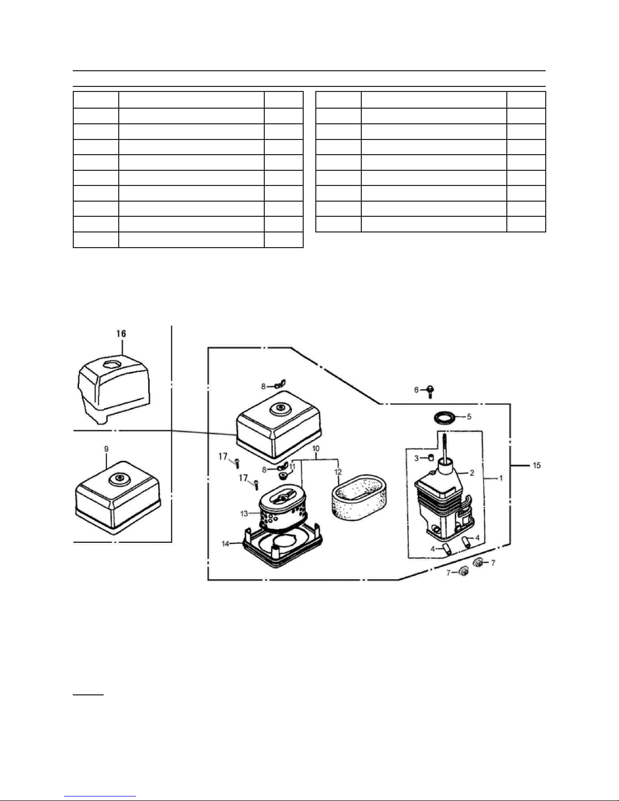
AIR CLEANER PARTS LIST & DIAGRAM
Part # Description Qty
1N Air Cleaner Assembly 1
2N Elbow 1
3N Short Collar 2
4N Long Collar 2
5N Elbow Packing 1
6N Bolt 6x20 1
7N Nut 6mm 2
8N Nut 2
9N Air Cleaner Cover 1
Part # Description Qty
10N Air Cleaner Element Assembly 1
11N Grommet 1
12N Outer Filter 1
13N Element 1
14N Noise Silencer 1
15N Air Cleaner Assembly 1
16N Cover 1
17N Screw 2
When ordering parts for this component be sure to use the correct sufx.
Note: Some parts are listed and shown for illustration purposes only, and are not avail-
able individually as replacement parts.
Page 34SKU 65075 For technical questions, please call 1-800-444-3353.
Page 35
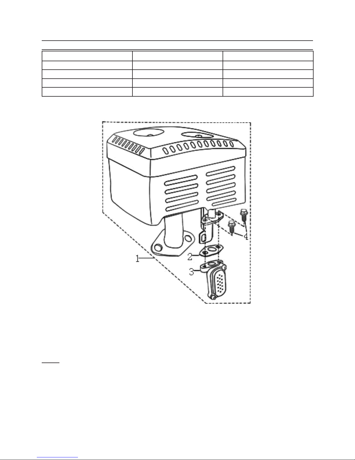
MUFFLER PARTS LIST & DIAGRAM
Part # Description Qty
1P Mufer Assembly 1
2P Gasket 1
3P Air Valve 1
4P Bolt 2
When ordering parts for this component be sure to use the correct sufx.
Note: Some parts are listed and shown for illustration purposes only, and are not avail-
able individually as replacement parts.
Page 35SKU 65075 For technical questions, please call 1-800-444-3353.
Page 36
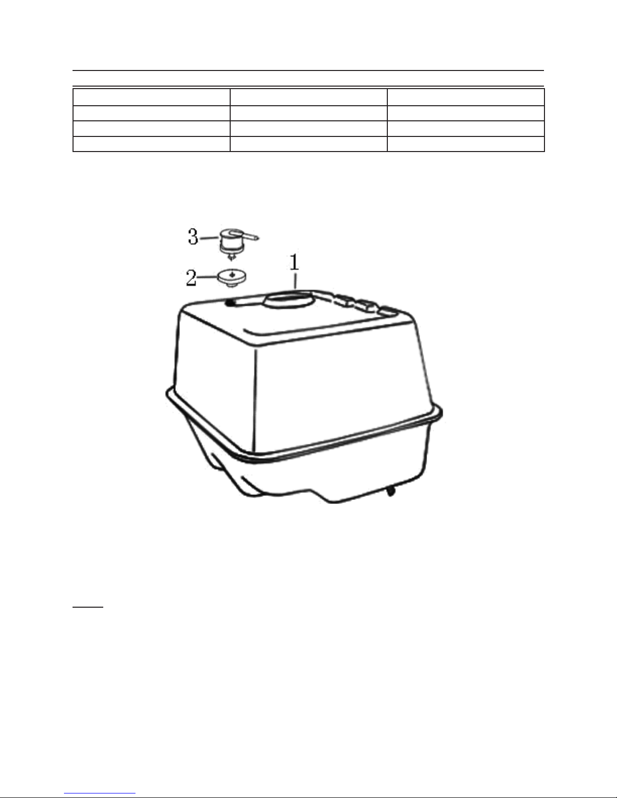
FUEL TANK PARTS LIST & DIAGRAM
Part # Description Qty
1R Fuel Tank Assembly 1
2R Valve 1
3R Gasket 1
When ordering parts for this component be sure to use the correct sufx.
Note: Some parts are listed and shown for illustration purposes only, and are not avail-
able individually as replacement parts.
Page 36SKU 65075 For technical questions, please call 1-800-444-3353.
Page 37
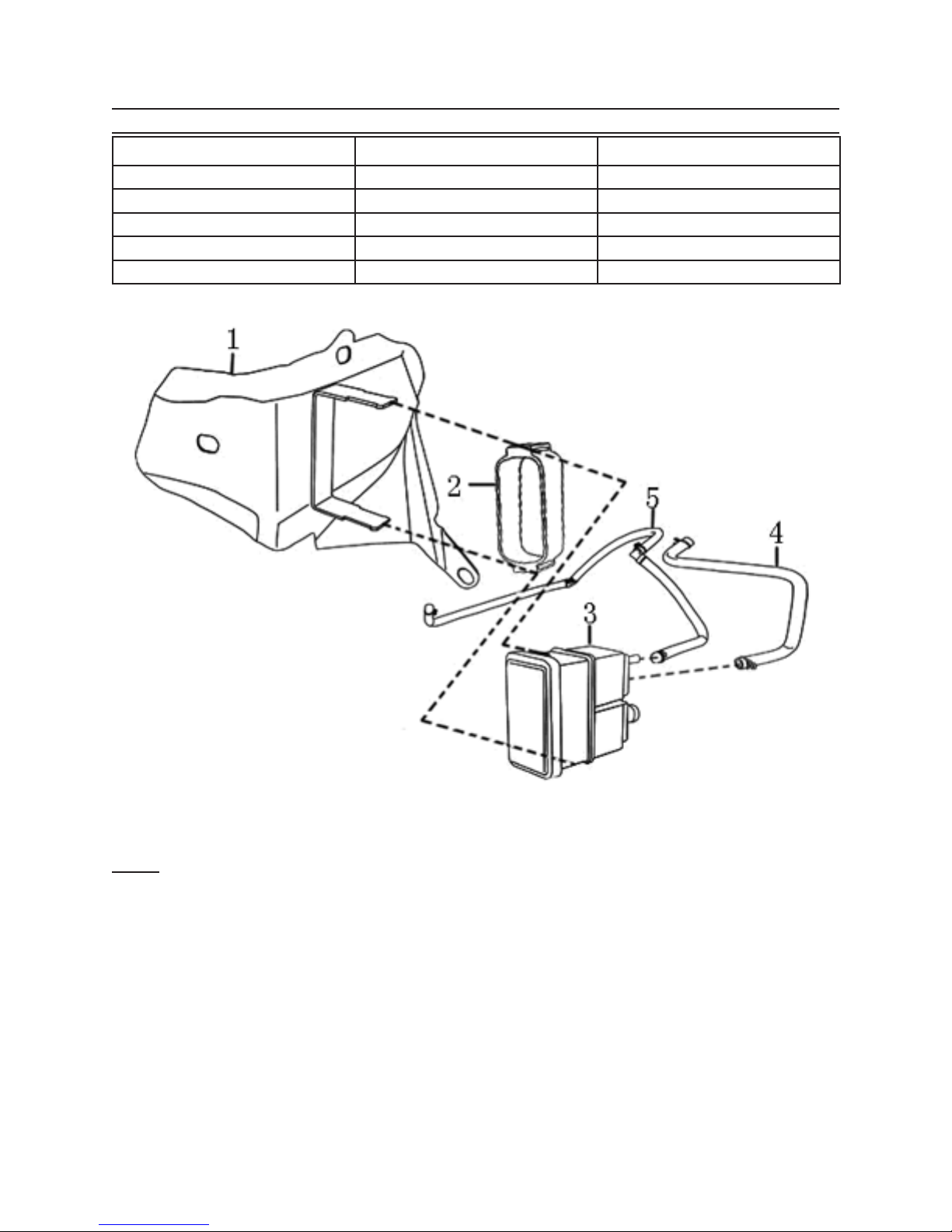
CARBON CANISTER ASSEMBLY
PART DESCRIPTION QTY
1S Shroud 1
2S Mount 1
3S Carbon Canister 1
4S Canister Vent 1
5S Canister Vent 1
When ordering parts for this component be sure to use the correct sufx.
Note: Some parts are listed and shown for illustration purposes only, and are not avail-
able individually as replacement parts.
Page 37SKU 65075 For technical questions, please call 1-800-444-3353.
Page 38

LIMITED 1 YEAR / 90 DAY
WARRANTY
Harbor Freight Tools Co. makes every effort to assure that its products meet
high quality and durability standards, and
warrants to the original purchaser that
for a period of ninety days from date of
purchase that the engine/motor, the belts
(if so equipped), and the blades (if so
equipped) are free of defects in materials
and workmanship. Harbor Freight Tools
also warrants to the original purchaser,
for a period of one year from date of purchase, that all other parts and components
of the product are free from defects in materials and workmanship (90 days if used
by a professional contractor or if used as
rental equipment). This warranty does not
apply to damage due directly or indirectly,
to misuse, abuse, negligence or accidents,
repairs or alterations outside our facilities,
normal wear and tear, or to lack of maintenance. We shall in no event be liable for
death, injuries to persons or property, or
for incidental, contingent, special or consequential damages arising from the use
of our product. Some states do not allow
the exclusion or limitation of incidental or
consequential damages, so the above
limitation of exclusion may not apply to
you. THIS WARRANTY IS EXPRESSLY
IN LIEU OF ALL OTHER WARRANTIES,
EXPRESS OR IMPLIED, INCLUDING
THE WARRANTIES OF MERCHANTABILITY AND FITNESS.
To take advantage of this warranty,
the product or part must be returned to us
with transportation charges prepaid. Proof
of purchase date and an explanation of the
complaint must accompany the merchan-
dise. If our inspection veries the defect,
we will either repair or replace the product
at our election or we may elect to refund
the purchase price if we cannot readily
and quickly provide you with a replacement. We will return repaired products at
our expense, but if we determine there is
no defect, or that the defect resulted from
causes not within the scope of our warranty, then you must bear the cost of returning
the product.
This warranty gives you specic legal
rights and you may also have other rights
which vary from state to state.
3491 Mission Oaks Blvd. • PO Box
6009 • Camarillo, CA 93011 • (800)
444-3353
EMISSION CONTROL
SYSTEM WARRANTY
California and United States Emission Control
Defects Warranty Statement
The California Air Resources Board (herein CARB), the United
States Environmental Protection Agency (herein EPA), and Harbor
Freight Tools (herein HFT) are pleased to explain the emission control system warranty on your 1995 and later Small Off-Road Engine
(herein engine). In California, the engine must be designed, built
and equipped to meet the State’s stringent anti-smog standards.
Elsewhere within the United States, new off-road, spark-ignition
engines certied for model year 1997 and later, must meet similar
standards set forth by the EPA. HFT must warrant the emission
control system on your engine for the periods of time described
below, provided there has been no abuse, neglect or improper
maintenance of your engine.
Your emission control system may include parts such as the
carburetor or fuel-injection system, and the ignition system. Also
included may be hoses, belts, connectors and other emissionrelated assemblies.
Where a warrantable condition exists, HFT will repair your
engine at no cost to you including diagnosis, parts and labor.
Manufacturer’s Warranty Coverage
The 1995 and later engines are warranted for two (2) years.
If any emission-related part on your engine is defective, the part
will be repaired or replaced by HFT.
Harbor Freight Tools Emission Control Defects
Warranty Coverage
Engines are warranted for a period of two (2) years relative to
emission control parts defects, subject to the provisions set forth
below. If any emission related part on your engine is defective, the
part will be repaired or replaced by HFT.
Page 38SKU 65075 For technical questions, please call 1-800-444-3353.
Page 39

Owner’s Warranty Responsibilities
As the engine owner, you are responsible for the performance •
of the required maintenance listed in your Owner’s Manual.
HFT recommends that you retain all receipts covering maintenance on your engine, but HFT cannot deny warranty
solely for the lack of receipts or for your failure to ensure the
performance of all scheduled maintenance.
As the engine owner, you should, however, be aware that •
HFT may deny you warranty coverage if your engine or a part
has failed due to abuse, neglect, improper maintenance, or
unapproved modications.
You are responsible for shipping your engine to a HFT war-•
ranty station as soon as a problem exists. Contact the HFT
Customer Service department at the number below to make
shipping arrangements. The warranty repairs should be
completed in a reasonable amount of time, not to exceed
30 days.
If you have any questions regarding your warranty rights
and responsibilities, you should contact the Harbor Freight Tools
Customer Service Department at 1-800-444-3353.
Harbor Freight Tools Emission Control Defects
Warranty Provisions
1. Length of Coverage
HFT warrants to a rst retail purchaser and each subsequent
purchaser that the engine is free from defects in materials
and workmanship that cause the failure of warranted parts
for a period of two (2) years after the date of delivery to the
rst retail purchaser.
2. No Charge Repair or Replacement
Repair or replacement of any warranted part will be performed
at no charge to the owner if the work is performed through a
warranty station authorized by HFT. For emissions warranty
service, contact the HFT Customer Service Department at
1-800-444-3353.
3. Consequential Damages Coverage
Coverage under this warranty shall also extend to the failure
of any engine components caused by the failure of any war-
ranted part while it is still covered under this warranty.
4. Coverage Exclusions
Warranty claims shall be led in accordance with the provi-
sions of the HFT warranty policy explained in the box at the
top of the previous page. HFT shall not be liable for any loss
of use of the engine, for any alternative usage, for any damage
to goods, loss of time, or inconvenience. Warranty coverage
shall also be excluded for any part which fails, malfunctions,
or is damaged due to failure to follow the maintenance and
operating instructions set forth in the Owner’s Manual includ-
ing, but not limited to:
Use of parts which are not authorized by HFTa)
Improper installation, adjustment or repair of the engine b)
or of any warranted part unless performed by an authorized warranty center
Failure to follow recommendations on fuel use contained c)
in the Owner’s Manual
Improper or inadequate maintenance of any warranted d)
parts
Repairs performed outside of the authorized warranty e)
service dealers
Alterations by changing, adding to or removing parts f)
from the engine.
5. Service and Maintenance
Component parts which are not scheduled for replacement
as required maintenance or are scheduled only for regular
inspection to the effect of “repair or replace as necessary”
are warranted for the warranty period. Any warranted part
which is scheduled for replacement as required maintenance
is warranted for the period of time up to the rst scheduled
replacement point for that part. Any replacement part, provided it is equivalent in durability and performance, may be
used in performance of maintenance or repairs. The owner
is responsible for commissioning a qualied technician/mechanic to perform all required maintenance, as outlined in
the Inspection, Cleaning, and Maintenance section in this
manual.
6. Warranted Parts
1) Fuel Metering System
Carburetor and its internal parts.i)
Fuel pump (if so equipped).ii)
Cold start enrichment system.iii)
2) Air Induction System
Intake pipe/manifold.i)
Air cleaner.ii)
3) Ignition System
Spark plug.i)
Magneto ignition system.ii)
4) Catalyst System (if so equipped)
Exhaust pipe stud.i)
Mufer.ii)
Catalytic converter (if so equipped).iii)
5) Miscellaneous Items Used in Above Systems
Vacuum, temperature and time sensitive valves i)
and switches.
Hoses, belts, connectors, and assemblies.ii)
Page 39SKU 65075 For technical questions, please call 1-800-444-3353.
 Loading...