

Page 1

10 TON LOG SPLITTER
39981
ASSEMBLY & OPERATING INSTRUCTIONS
Diagrams within this manual may not be drawn proportionally.
Due to continuing improvements, actual product may differ slightly from the product described herein.
Distributed exclusively by Harbor Freight Tools®.
3491 Mission Oaks Blvd., Camarillo, CA 93011
Visit our website at: http://www.harborfreight.com
Read this material before using this product.
Failure to do so can result in serious injury.
SAVE THIS MANUAL.
Copyright© 1999 by Harbor Freight Tools®. All rights reserved. No portion of this manual
or any artwork contained herein may be reproduced in any shape or form without the
express written consent of Harbor Freight Tools.
For technical questions or replacement parts, please call 1-800-444-3353.
Page 2

THANK YOU for choosing a HARBOR FREIGHT TOOLS product. For future reference, please complete the
owner’s record below:
Model Serial No. Purchase Date
SAVE THE RECEIPT, WARRANTY AND THESE INSTRUCTIONS. It is important that you read the entire
manual to become familiar with the unit BEFORE you begin assembly.
Technical Specifications
Tool Name: Log Splitter-10 Ton Horizontal
Item Number: 39981
Capacity: 10 Ton
Ram Diameter: 1.572”
Ram Travel: 7”
Minimum Log Capacity: 15-1/2” Long
Maximum Log Capacity: 18-1/2” Long
Maximum Log Diameter: 6-1/2”
Weight: 100 Lbs.
Overall Length: 12-1/8”
Overall Width: 7-1/4”
Overall Height: 43”
Handle Length: 29-1/2”
Warning: The warnings, cautions and instructions discussed in this instruction manual
cannot cover all possible conditions and situations that may occur. It must
be understood by the operator that COMMON SENSE AND CAUTION ARE
FACTORS WHICH CANNOT BE BUILT INTO THIS PRODUCT, BUT
MUST BE SUPPLIED BY THE OPERATOR.
The Operator
PLEASE REMEMBER:
Do not operate the product if under the influence of alcohol or drugs. Read warning labels on prescriptions to
determine if your judgment/reflexes might be impaired.
Do not wear loose clothing or jewelry as they can be caught in moving parts.
Protective gloves and non-skid footwear is recommended.
Wear restrictive hair covering to contain long hair.
Use eye and ear protection. Always wear ANSI approved impact safety goggles.
Maintain proper footing and balance at all times.
#39981 Page 2
Page 3

Work Area
TO AVOID RISK OF PERSONAL INJURY, EQUIPMENT DAMAGE, FIRE AND SHOCK, MAKE SURE YOUR
WORK AREA IS:
Free of damp, wet or rainy conditions.
Free of children (never let them handle tools or machinery).
Well-lit.
Clean and uncluttered.
Before Operating
Before using any tool, any part that appears damaged should be carefully checked to determine that it will
operate properly and perform its intended function.
Before operating your Log Splitter check for damaged parts. You should also:
Make sure all clamps, locks and bolts are tight.
Keep Guards in place and in working order.
Assembly
Your Log Splitter requires some limited assembly. Please refer to Figure 1, and to the
Assembly Diagram on page 7 and Parts List on page 6 as needed for assembly and
operation. Unpack the Log Splitter at the place that you will be using it. The Log Splitter
is heavy, so be certain to use proper lifting techniques when moving and placing the Log
Splitter.
To complete the assembly, insert each Handle (A-16) into each Socket (A-25) as shown in
Figure 1. Your Log Splitter will then be ready to operate.
Handle (A-16)
Log Splitter Assembly
Socket (A-25)
Figure 1-Operating Handle Instruction
#39981 Page 3
Rev 08l
Page 4
Operation
Never force the tool or attachment to do the work of a larger industrial tool. It is designed to do the job better
and more safely at the rate for which it was intended.
Step 1) Make certain that the maximum length of each log to be split does not exceed
18-1/2”. If the log exceeds this length, it must be cut to no longer than 18-1/2”.
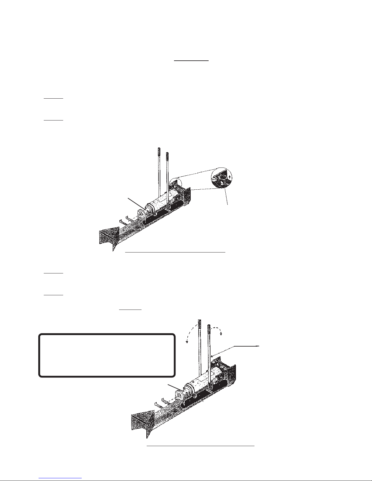
Step 2) Made certain that the Piston Rod (A-32) is fully retracted into the Cylinder
(A-36). If not fully retracted, turn the Release Screw (A-44) counterclockwise to
release the hydraulic pressure. Once this is completed, and the Piston Rod is
fully retracted into the Cylinder, tighten the Release Screw.
Piston Rod (A-32)
Release Screw (A-44)
Figure 2-Retracting the Piston Rod
Step 3) Place the log between the Wedge and the Piston Assembly, resting the log in
the metal Cradle.
Step 4) Grip one Handle (A-16) in each hand and move them in a back-and-forth motion
with one lever being pushed fully forward and one lever being pulled fully rearward.
Please see Figure 3 for illustration of this step.
Warning: When splitting wood, make sure
the area around the Wedge and Piston Assembly
is clear of people to avoid the possibility of injury
from falling wood pieces.
Never let children use the Log Splitter. Keep children
away from the work area at all times.
Operating Lever
Piston Rod (A-32)
#39981 Page 4
Figure 3-Operation of the Log Splitter
Rev 08l
Page 5
Step 5) Repeat Step 4 to advance the Piston Rod (A-32) forward. This will push the log
against the Wedge and split the log.
Step 6) Once the Log is split, remove the pieces from the Log Splitter. Turn the Release
Screw counterclockwise so that the Piston retracts back into the Cylinder as in
Step 2 (see Figure 2). Tighten the Release Screw once the Piston Rod is fully
retracted.
Step 7) Continue the preceding steps until all logs have been split. Once completed,
your Log Splitter should be stored with the Release Screw (A-49) opened so
that any hydraulic pressure is relieved during non-use.
i f t h e r e i s a n y q u e s t i o n a b o u t a c o n d i t i o n b e i n g s a f e o r u n s a f e , d o n o t o p e r a t e t h e t o o l .
Maintenance
After every use, wipe down the Log Splitter to remove any tree sap or dirt occurring during use. This will
extend the use of the Log Splitter.
Bleeding the Log Splitter
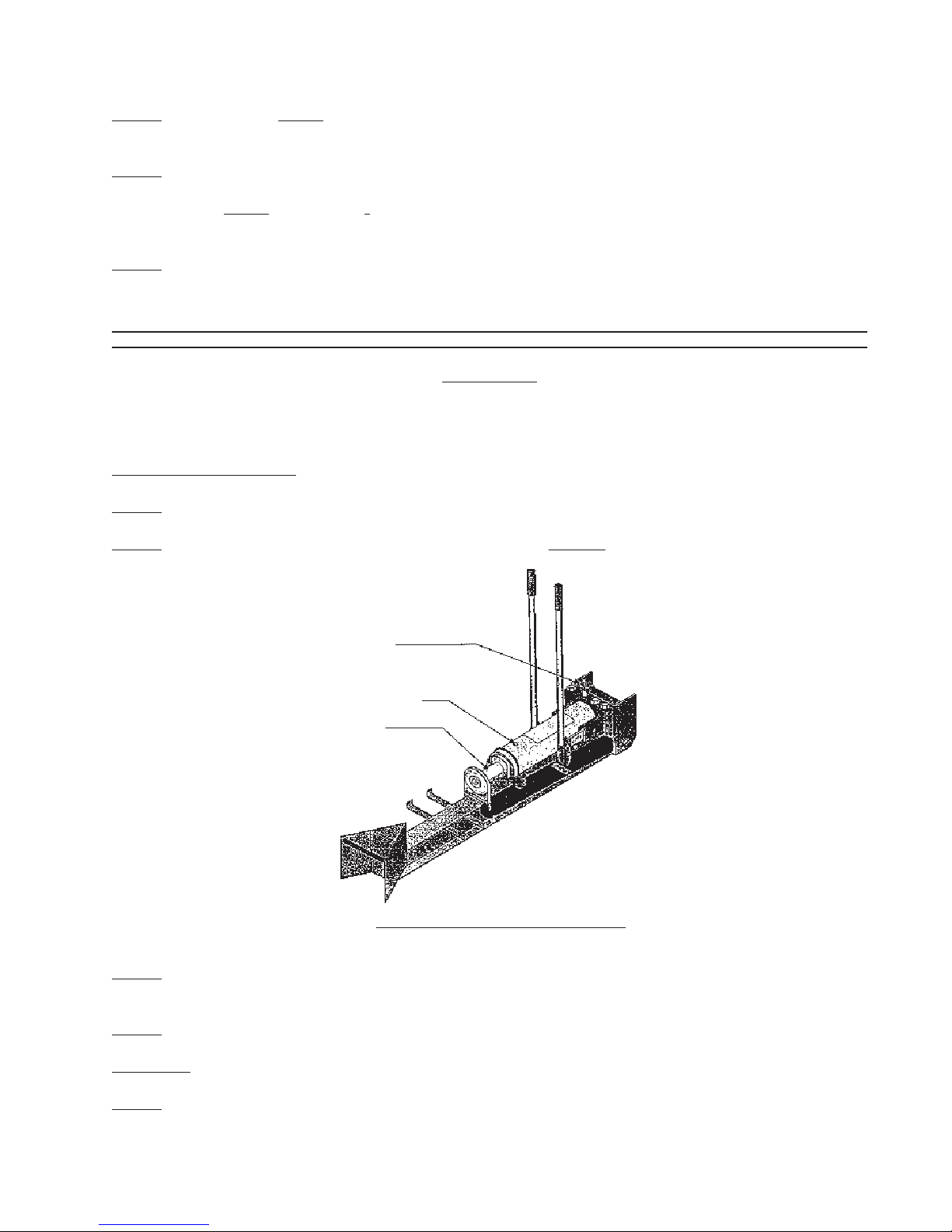
Step 1) Operate the Log Splitter so that the Piston Rod (A-32) is extended to its maximum length.
Step 2) Remove the Oil Filling Plug (A-56) as shown in Figure 4.
Release Screw
Oil Filling Plug (A-56)
Piston Rod
Figure 4-Bleeding the Log Splitter
Step 3) Turn the Release Screw (A-44) counterclockwise as fast as possible. The
Piston Rod will retract into the Cylinder and push air out of the Oil Filling Hole.
Step 4) Replace the Oil Filling Plug. Repeat steps one (1) through four (4) as necessary.
Adding Oil
Step 1) The Log Splitter uses Hydraulic oil. If you need to add oil to the Log Splitter,
remove the Oil Filling Plug and add oil until the Log Splitter is 3/4 full.
#39981 Page 5
Rev 08l
Page 6

Unpacking
UNPACK AND CHECK CONTENTS
When unpacking your Log Splitter, check to make sure the following parts are included. If any parts are
missing or broken, please call HARBOR FREIGHT TOOLS at 1-800-444-3353.
Parts List
Part # Description Quantity Part # Description Quantity
A-1 Nut 2 A-29 O - Ring 2
A-2 Washer 2 A-30 Pump Body 1
A2-1 Washer 4 A-31 Washer 1
A-3 Split Pin 9 A-32 Piston Rod 1
A-4 Shaft 1 A-33 O-Ring Returner 1
A-5 Wheel 2 A-34 O-Ring 1
A-6 Pin 2 A-35 Retaining Ring 1
A-7 Washer 2 A-36 Cylinder 1
A-8 Spring Washer 2 A-37 O-Ring 1
A-9 Bolt 2 A-38 Valve Base 1
A-10 Frame 1 A-39 Ball 3
A-11 Bush 1 A-40 Ball 2
A-12 Top Plate 1 A-41 Bolt 2
A-13 Pin 1 A-42 O-Ring 1
A-14 Spring 2 A-43 Release Pin 1
A-15 U-Clamp 1 A-44 Release Screw 1
A-16 Handle 2 A-45 Pin 1
A-17 Power Unit Assy. 1 A-46 Ball 1
A-18 O-Ring 1 A-47 Retainer 1
A-19 Gland Nut 1 A-48 Spring 1
A-20 O-Ring 1 A-49 Regulate Bolt 1
A-21 Cistern 1 A-50 Pump Plunger 1
A-22 Rubber Washer 2 A-51 Washer 1
A-23 Hexagonal Bolts 2 A-52 O-Ring 1
A-24 Cistern Packing 1 A-52-1 O-Ring 1
A-25 Socket 2 A-53 Pump Body 1
A-26 Pin 6 A-54 Washer 1
A-27 Pump Plunger 1 A-55 Link 2
A-28 Washer 2 A-56 Oil Fill Plug 1
#39981 Page 6
Rev 99a, 08l
Page 7
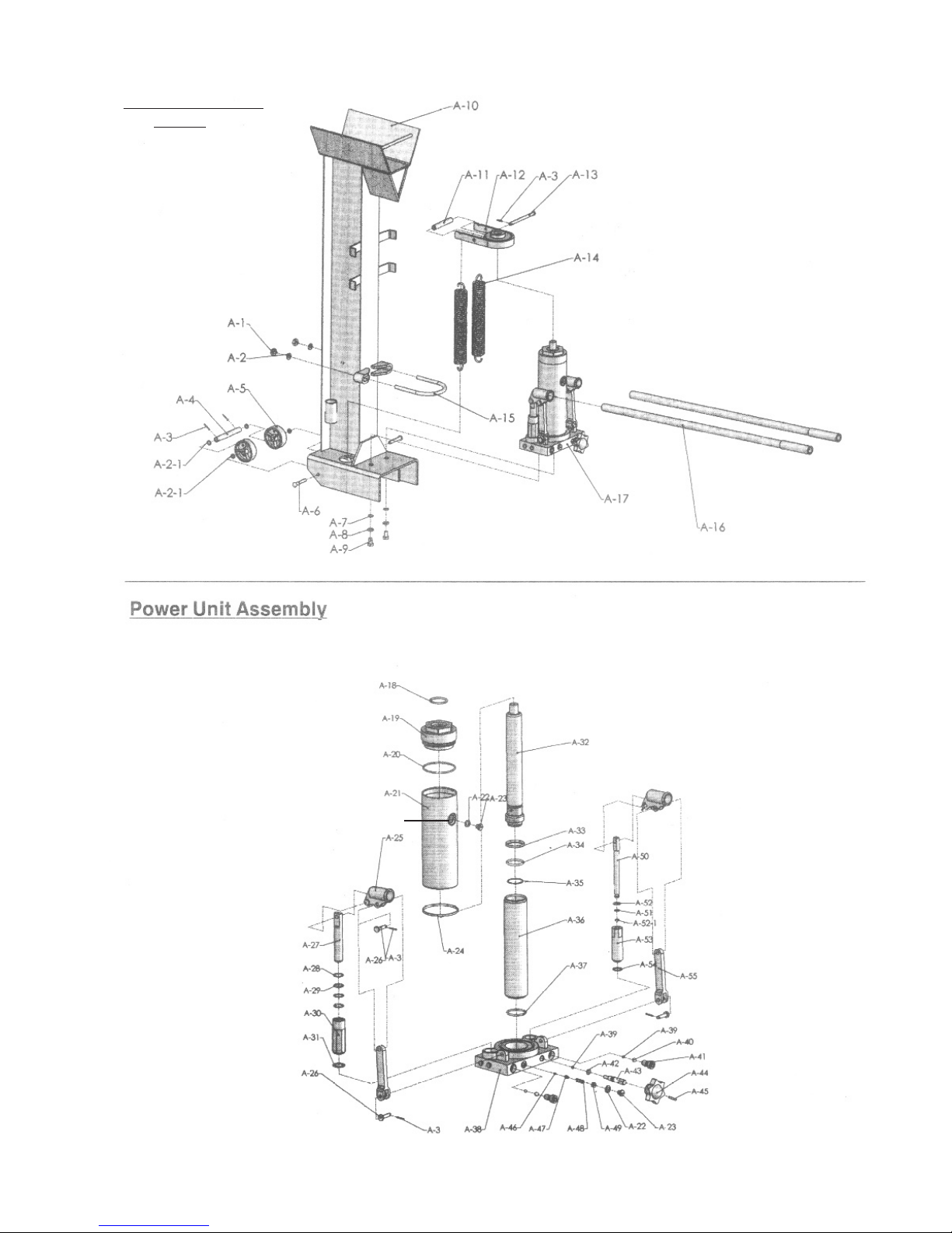
Assembly Diagram
#39981
#39981 Page 7
A-56
Rev 99a, 08l
Page 8

LIMITED 90 DAY WARRANTY
Harbor Freight Tools Co. makes every effort to assure that its products meet high quality
and durability standards, and warrants to the original purchaser that this product is free from
defects in materials and workmanship for the period of 90 days from the date of purchase. This
warranty does not apply to damage due directly or indirectly, to misuse, abuse, negligence or
accidents, repairs or alterations outside our facilities, criminal activity, improper installation,
normal wear and tear, or to lack of maintenance. We shall in no event be liable for death, injuries to persons or property, or for incidental, contingent, special or consequential damages
arising from the use of our product. Some states do not allow the exclusion or limitation of
incidental or consequential damages, so the above limitation of exclusion may not apply to
you. THIS WARRANTY IS EXPRESSLY IN LIEU OF ALL OTHER WARRANTIES, EXPRESS
OR IMPLIED, INCLUDING THE WARRANTIES OF MERCHANTABILITY AND FITNESS.
To take advantage of this warranty, the product or part must be returned to us with
transportation charges prepaid. Proof of purchase date and an explanation of the complaint
must accompany the merchandise. If our inspection verifies the defect, we will either repair or
replace the product at our election or we may elect to refund the purchase price if we cannot
readily and quickly provide you with a replacement. We will return repaired products at our
expense, but if we determine there is no defect, or that the defect resulted from causes not
within the scope of our warranty, then you must bear the cost of returning the product.
This warranty gives you specific legal rights and you may also have other rights which
vary from state to state.
3491 Mission Oaks Blvd. • PO Box 6009 • Camarillo, CA 93011 • (800) 444-3353
#39981 REV 08k Page 8
 Loading...