

Page 1
P/N R1740 ©2004
• This publication contains instructions for the installation of two separate parts: the Cat 5 Bullet & Infrared Camera, and the Cat 5
Camera Microphone.These parts are sold separately under unique part numbers.
• The Cat 5 Bullet & Infrared Camera includes a specially engineered mounting wall plate that is designed to be installed in a
standard single gang box.
• The Cat 5 Camera can be installed without the Cat 5 Camera Microphone, but the Camera Microphone must be installed with
the Camera mounting plate.
Before installing the Cat 5 Camera,please note:
Cat 5 Bullet & Infrared Camera (with optional microphone)
Installation Notes
1. Installing the Cat 5 Camera (with included mounting wall plate)
Rough-In
• The rough-in for this product is the same regardless if the microphone is installed or not.The
rough-in would consist of simply running a single Cat 5 line to a mounted single gang box in the
location of your choice.
Indoor Installation
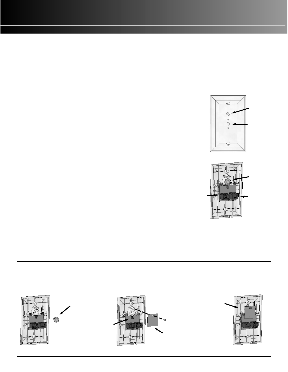
• Install the Cat 5 Camera mounting hardware on to the Cat 5 Camera Mounting Wall Plate.
Firmly screw in the mounting post (included with the camera) to the post mounting hole
(Figure 1) on the front of the plate.
• Mount the Cat 5 Camera to the mounting hardware.
• Plug the RJ-45 connector from the camera into the RJ-45 jack which is labeled “INPUT FROM
CAMERA” and is located on the rear of the mounting wall plate (Figure 2).
• Plug the roughed in Cat 5 line from the Cat 5 Camera Module (in the enclosure) into the RJ-45
jack which is labeled “OUTPUT TO CAMERA MODULE” and is located on the rear of the
mounting wall plate (Figure 2).
• Install the mounting wall plate on the single gang box in the proper direction (use the directional
arrow on the back of the plate that is marked “UP” as a guide). Be sure to route the camera Cat
5 cord through the opening in the bottom of the mounting wall plate and tuck
any excess Cat 5 cord into the single gang box behind the wall plate.
Outdoor Installation
Follow the Indoor Installation instructions (above) and follow this additional information:
• Use a standard single gang box that is labeled “Suitable for Wet Locations”.
• Install the included rubber gasket on the rear of the mounting wall plate and make sure it creates
a tight seal between the mounting wall plate and the gang box.The use of additional weatherproofing such as a silicon based caulk
may be desirable if direct exposure to moisture is likely. If a caulk is used then be sure not to caulk the bottom edge of the
mounting wall plate to allow moisture to escape.
• Ensure that the sealing cap is in place (Figure 2).
Post Mounting
Hole
Microphone
Screen
Figure 1
Sealing
Cap
INPUT FROM
CAMERA
Figure 2
OUTPUT TO
CAMERA MODULE
2. Installing the Cat 5 Camera Microphone (intended for indoor use only)
• Remove the sealing cap from the rear of the mounting wall plate (Figure 3).
• Carefully attach the Cat 5 Camera Microphone circuit board to the mounting wall plate circuit board.The pins on the Cat 5
Camera Microphone circuit board must be aligned with and plugged into the pin socket labeled “JP1” on the mounting wall plate
circuit board (Figure 4).
• Secure the Cat 5 Camera Microphone circuit board in place with the included screw (Figure 5).
Figure 3
Figure 4 Figure 5
Sealing
Cap
JP1 Pin Socket
Cat 5 Camera
Microphone Circuit
Board
Complete
Assembly
Page 2
P/N R1740 ©2004
Cat 5 Camera Solution Overview
The Cat 5 Camera Solution consists of a Cat 5 Camera Module, RJ-45 terminated cameras, and peripheral
devices such as modulators and quad processors.
The Cat 5 Camera module can support up to 4 cameras through the use of an onboard tunable sequencer,
and is compatible with single and multi-channel modulators. The camera module also provides power to the
camera over the Cat 5, further reducing the number of installed cables.
The camera solution provides four levels of camera offerings: a color weatherproof bullet camera, a
weatherproof black and white bullet camera, a weatherproof infrared black and white camera and an indoor
black and white mini camera. Audio can be added to any of the cameras by utilizing the Cat 5 Camera
mounting wall plate (included with select cameras) with the Cat 5 Camera Microphone.
Application Examples
PLEASE NOTE: Components such as power supplies are not shown in the diagrams but may or may not be included with the products shown below.
Please consult the current catalog for more information on required parts and components.
C ameras
Cat 5 Camera
Module
4 Way Video Module
2 x 2 Video Amplifier
Module
Modulator
1 C hannel
Modulator
3 C hannel
Modulator
3 C hannel
8 Way Video Module
RCA
C able
RCA
C ables
RCA
C ables
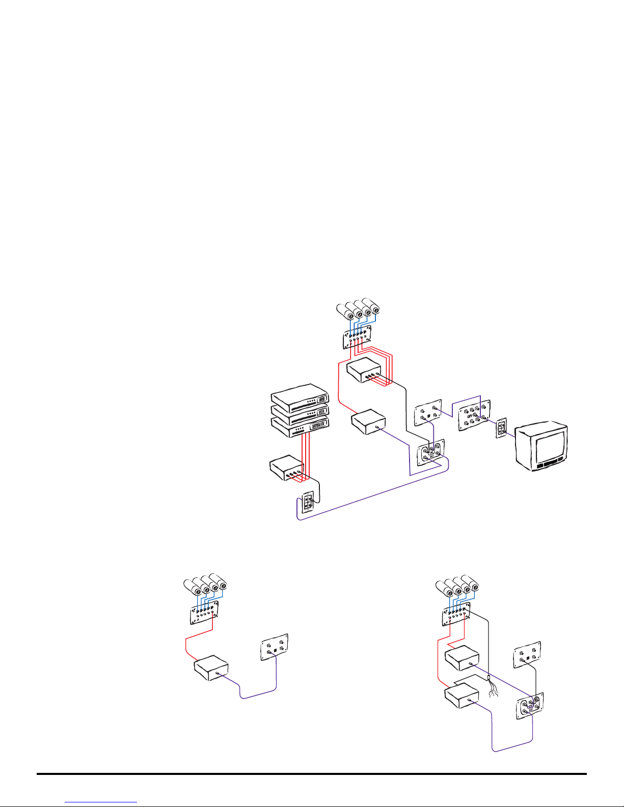
Example 1: Modulating Multiple Cameras
This drawing shows 4 cameras modulated
each on their own channel. It also shows
how to modulate additional devices, such as
DVDs and VCRs, along with the Cat 5
Cameras. Cable TV or off air antenna could
be added in this application by plugging the
main cable feed into the 2 x 2 Video
Amplifier Module using the port labeled
“CATV/ANT”. These broadcast signals
would be combined with the modulated
channels (modulated channels must be set
to “open” channels which are not used by
the CATV or off-air provider).
Example 2: Sequencing Cameras
This drawing shows 4
cameras sequenced on a
single channel.This is
accomplished by using the
built in tunable sequencer
output on the Cat 5
Camera module.The
sequencer can be tuned
to switch between
cameras at intervals between 1 and 30 seconds
(approximately).
Example 3: Sequencing & Modulating plus Audio
This drawing shows 4
cameras sequenced
on a single channel,
but in addition, one
camera is modulated
individually with audio
on a second channel
(ex: the front door).
The Cat 5 to RCA
cable is required to
supply audio to the
modulator.
C ameras
C at5 to
RCA
C able
C at 5 Camera
Module
RCA
C able
RCA
C able
Modulator
1 C hannel
2 x 2 Video Amplifier
Module
4 Way Video Modul e
C ameras
Cat 5 Camera
Module
RCA
C able
Modulator
1 C hannel
2 x 2 Video Amplifier
Module
 Loading...