

Page 1
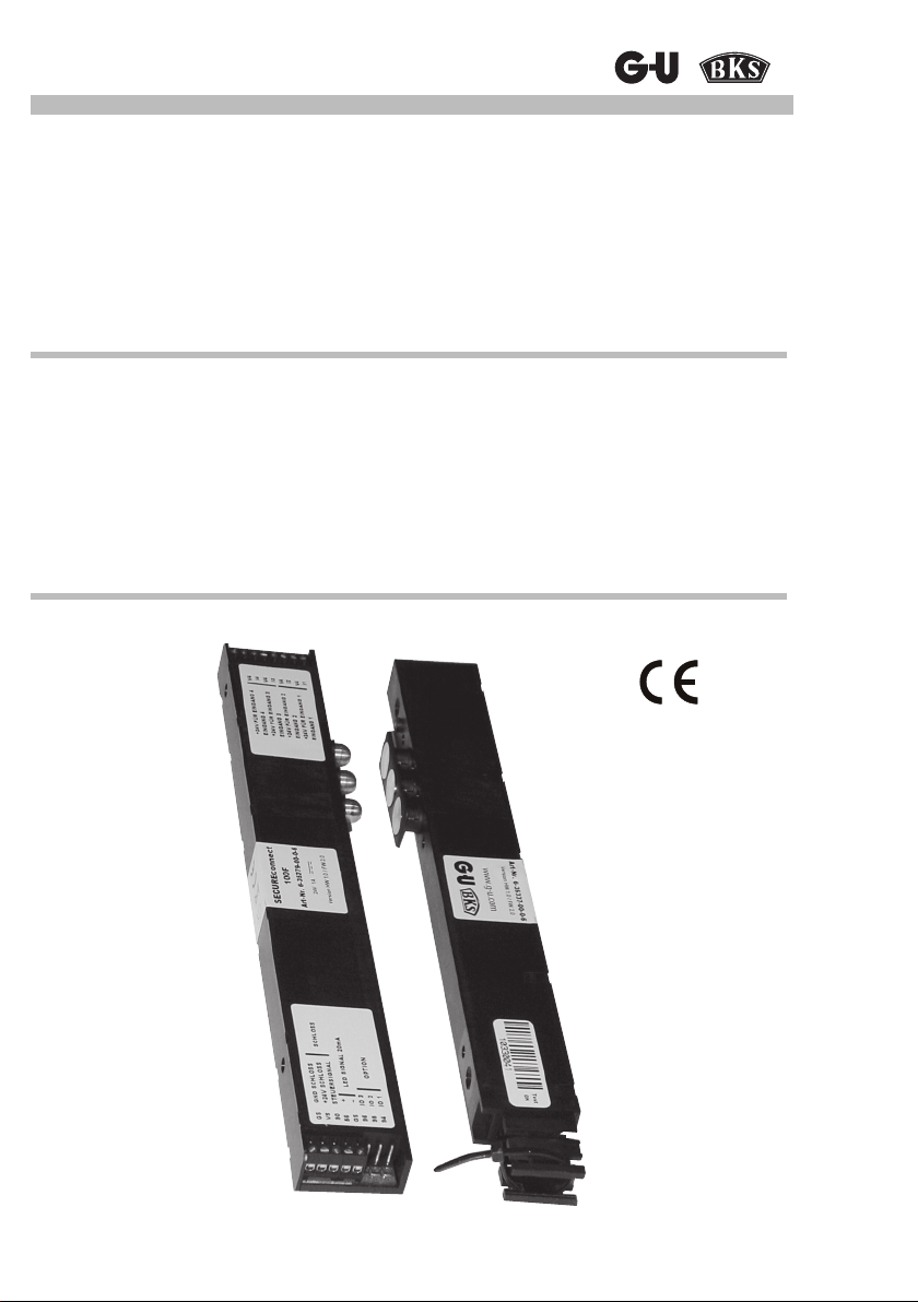
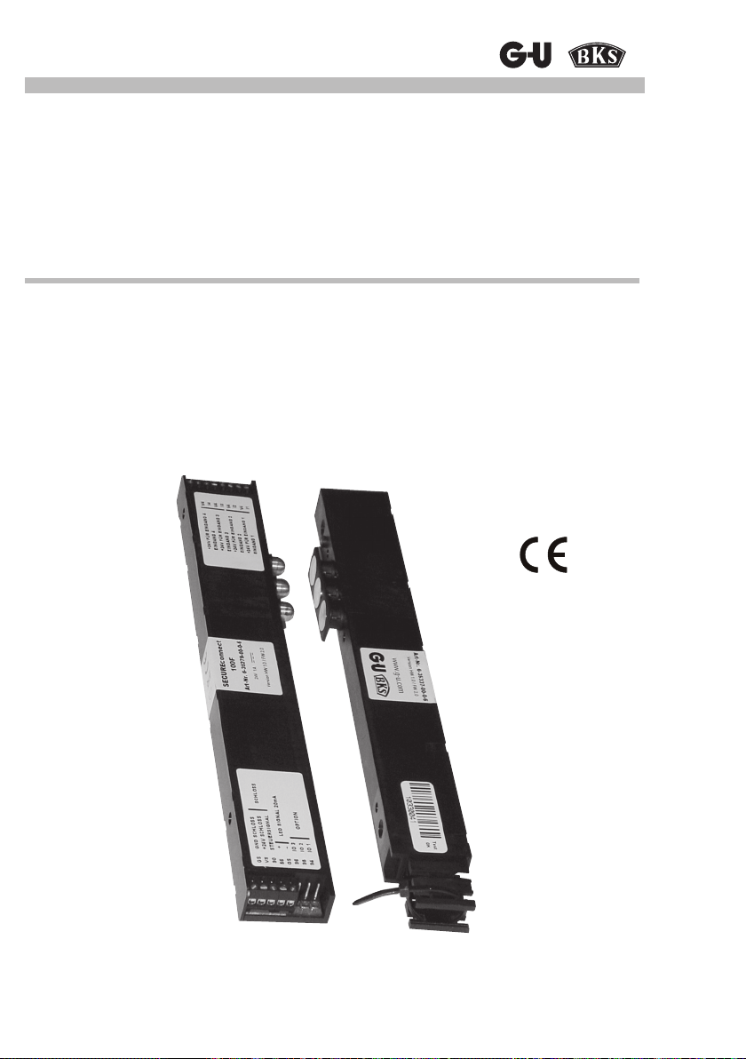
SECUREconnect 100
Strom- und Datenübertrager
Montage- und Bedienungsanleitung
Technisches Datenblatt
Seite 2
SECUREconnect 100
Power and Data Transmission Unit
Mounting and Operating Instructions
Technical Data Sheet
Page 29
Page 2

SECUREconnect 100
Inhalt
1 Information 3
1.1 Hinweise zur Anleitung 3
1.2 Packungsinhalt 3
2 Technische Beschreibung 4
2.1 Anwendungsbereich 4
2.2 Systemdarstellung 5
3 Sicherheitshinweise 6
4 Montagevorbereitung 7
4.1 Stulpblechmontage 7
4.2 Montage Kontaktträger und Kontaktplatte 7
4.3 Falzluft (Kammermaß) einstellen 8
4.4 Vorbereitung zum Einbau in die Tür 9
5 Anschlusshinweise 10
5.1 Leitungsverlegung und elektrischer Anschluss 10
5.2 Allgemeine Beschreibung der Anschlüsse SECUREconnect 100 10
5.3 Beschreibung der Anschlüsse SECUREconnect 100F (Flügelteil) 10
5.4 Beschreibung der Anschlüsse SECUREconnect 100R (Rahmenteil) 13
6 Inbetriebnahme 15
6.1 Aufbau der Kommunikation 15
6.2 LED - Signalisierung 16
6.3 Funktionen mit elektromotorischen Schlössern 17
6.4 Funktionen mit elektromechanischen Schlössern (EK) 18
6.5 Elektrische Funktionsprüfung 19
7 Anschlusszeichnungen 20
7.1 Fallenriegelüberwachung 20
7.2 Anschlussplan Secury Automatik mit A-Öffner 20
7.3 Ein- und Ausschalten des Tonsignals im A-Öffner 21
7.4 Anschlussplan Motorschloss
Serie 19 (mit 14 poligem Anschlusskabel) 22
7.5 Anschlussplan EK-Schloss
Serie 19 (mit 14 poligem Anschlusskabel) 23
7.6 Anschlussplan EK-Schloss
Serie 21 (mit 14 poligem Anschlusskabel) 24
7.7 Anschlussplan EK-Schloss
Serie 21 (mit 8 poligem Anschlusskabel) 25
7.8 Ansteuerung über IO10 Module 26
8 Inspektions- und Wartungsarbeiten, Ersatzteile 28
9 Entsorgung 28
2
Page 3
Strom- und Datenübertrager
1 Information
Vielen Dank, dass Sie sich für das SECUREconnect 100 als Energie- und Datenübertragungsgerät für motorische oder elektromechanische Verschlusssysteme entschieden haben. Damit
haben Sie sich für eine sichere und kompakte Energie- und Datenübertragung entschieden.
1.1 Hinweise zur Anleitung
Die Anleitung enthält wichtige Hinweise und hilft, Gefahren zu vermeiden, Reparaturkosten und
Ausfallzeiten zu vermindern und die Zuverlässigkeit und Lebensdauer des
SECUREconnect 100 zu erhöhen.
Die Bedienungsanleitung ist von jeder Person zu lesen und anzuwenden, die mit dem
SECUREconnect 100 arbeitet, z.B. bei:
• Montage und Anschluss
• Inbetriebnahme und Wartung
Die Angaben dieser Bedienungsanleitung, insbesondere die Kapitel über Sicherheitshinweise,
sind unbedingt zu beachten.
Die Bedienungsanleitung ist nach dem Montageabschluss dem Betreiber zu übergeben. Lesen
Sie diese Anleitung vor der ersten Bedienung bitte sorgfältig durch und bewahren Sie diese
auch für die spätere Nutzung auf. Weisen Sie bitte alle Betreiber / Verantwortliche an, die
Bedienungsanleitung zu lesen.
1.2 Packungsinhalt
Der Packungsinhalt enthält:
Packungsinhalt
Anzahl Bezeichnung
1 Stk. SECUREconnect 100R (für Türrahmen)
1 Stk. SECUREconnect 100F (für Türügel)
4 m 230V Netzkabel mit Eurostecker
4 m Anschlusskabel mit Klemmen für Eingänge
1 Stk. SECUREconnect 100R Kontaktträger aus Kunststoff mit 3 Kontaktplatten
1 Beutel 8 x Stulp-Befestigungsschrauben,
1 Stk. Montage- und Bedienungsanleitung
1 Stk. Einbauanleitung
1 x Kabeltülle, 1 x zusätzl. Kabelbinder zur Zugentlastung
3
Page 4

SECUREconnect 100
2 Technische Beschreibung
2.1 Anwendungsbereich
Das SECUREconnect 100R und -F ist zum lotrechten Einbau in Türen und Türrahmen vorgesehen.
Der Betrieb in freistehenden Toranlagen oder in Türen, deren Umgebungsbedingungen eine
höhere Schutzart als IP 40 erfordern, ist nicht zulässig.
SECUREconnect 100 darf nicht für andere als die zuvor genannten Zwecke eingesetzt
werden.
Die Einhaltung der vom Hersteller vorgeschriebenen Montage- und Bedienungsanleitung gehört
zur bestimmungsgemäßen Verwendung, nur so können Schäden vermieden werden.
Ausgeführte Veränderungen am Schloss oder am Anschluss des Schlosses ohne Zustimmung
der Firmen GU und BKS, schließen eine Haftung des Herstellers für daraus resultierende
Schäden aus.
• Geeignet zum Einbau in Holz-, Kunststoff- und Metalltürsysteme unter Verwendung von
aufschraubbaren, auf das Türsystem abgestimmten Stulpen.
• Kurzschlussfeste Energieübertragung zwischen Türrahmen und Türügel.
• Verschlüsselte Datenübertragung.
Es gelten die allgemeinen Geschäftsbedingungen der Fa. GU.
SECUREconnect 100R zum Einbau in den Türrahmen
• Energie- und Datenübertragungsgerät für motorische oder elektromechanische Verschlusssysteme der Firmen GU und BKS.
• Kommunikationsschnittstelle zum GU-BKS-NET - Bus und Ausgabe von Schlosszuständen an IO10 (Relaisbox).
• LED Anzeige zur Zustandssignalisierung.
• Spannungsversorgung wahlweise 24V DC oder 230V AC.
SECUREconnect 100F zum Einbau in den Türügel
• Energie- und Datenübertragungsgerät für motorische oder elektromechanische Verschlusssysteme der Firmen GU und BKS.
• Langlebige Stößelkontakte (Kabelübergang entfällt).
• Beliebige Türöffnungsweite.
• Ungehindertes Ein- und Aushängen der Tür.
• 4 Eingänge zur Übertragung von Schlosszuständen.
• Stromausgang 20 mA zum Anschluss einer LED als Öffnungssignalisierung.
• LED Anzeige zur Zustandssignalisierung.
• Modulschacht zur Aufnahme von Erweiterungsmodulen für zukünftige Anwendungen.
• Im eingebauten Zustand wartungsfrei.
Betriebsparameter
Versorgungsspannung 230V AC 50/60 Hz 0,25 A oder 24V DC stabilisiert 1,0 A
Schutzart IP 40
Schutzklasse II
Betriebstemperatur -20 °C … +45 °C
4
Page 5
Strom- und Datenübertrager
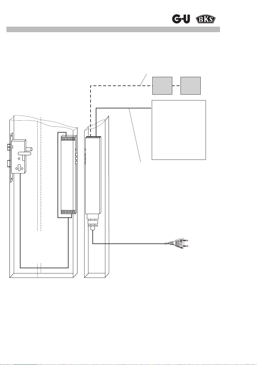
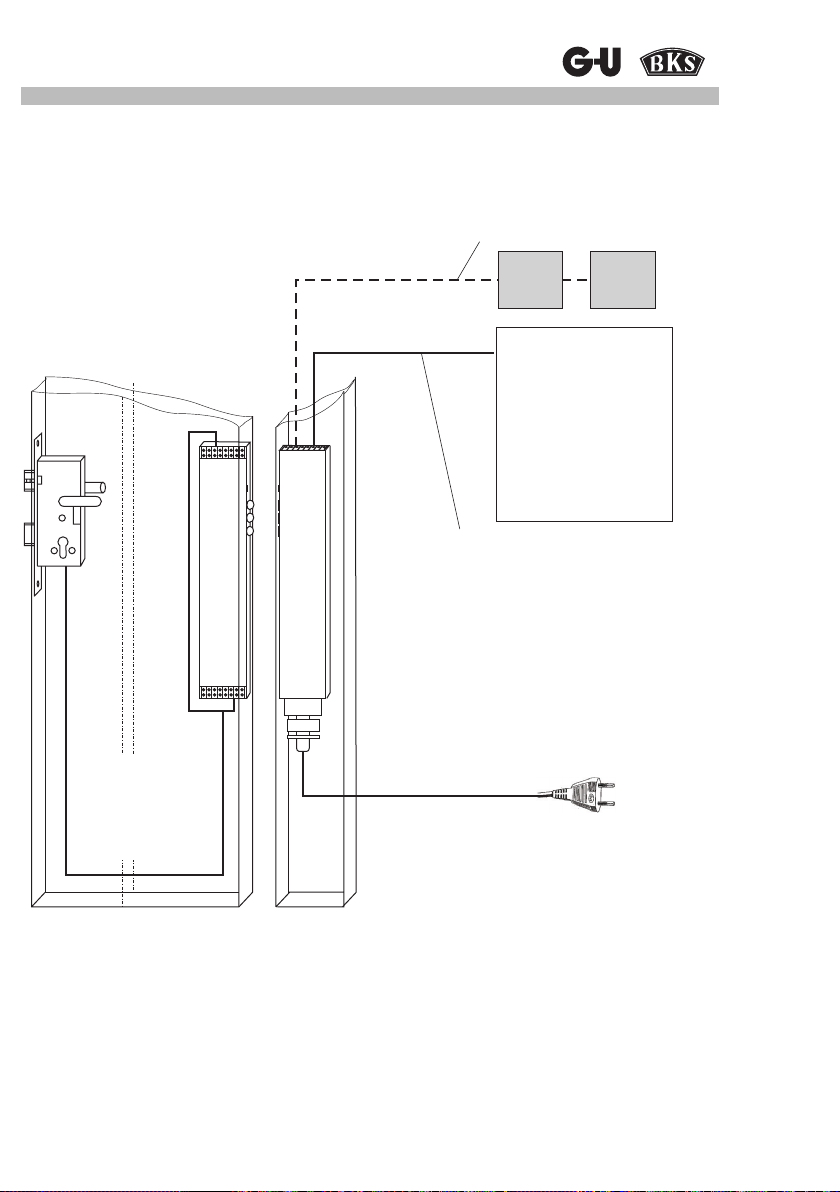
2.2 Systemdarstellung
J-Y(ST) Y2x2x0.6
Ansteuermöglichkeiten siehe
Kap. 5
SECUREconnect 100F
SECUREconnect 100R
IO10
Potenzialfreier Ansteuerkontakt
z.B.
Taster,
Sprechanlage,
Zutrittskontrolle,
Zeitschaltuhr.
Ansteuermöglichkeiten
siehe Kap. 6
Anschlusskabel mit Klemmen für Eingänge
Bei Metall- und Kunststofftüren zum
Leitungsauslass beigefügte Kabeltülle
verwenden.
IO10
Tür mit SECUREconnect 100F
(Position und Kabel)
Detaillierte Einfräsmaße stehen auf der
Zeichnung 0-45733-LO zur Verfügung.
Rahmen mit SECUREconnect 100R
Position und Kabel
(230V AC, 24V DC, BUS, Ansteuerleitung, IO10)
5
Page 6
SECUREconnect 100
3 Sicherheitshinweise
Es ist zu gewährleisten, dass nur Fachkräfte (Denition siehe EN 50110-1, DIN VDE 0105 bzw.
IEC 60364) mit jeglichen Arbeiten (Planung, Transport, Montage, Installation, Inbetriebnahme,
Wartung, Reparatur, Demontage) an den Betriebsmitteln beauftragt werden.
Dabei ist sicherzustellen, dass ihnen die Unterlagen zur Aufstellung, Inbetriebnahme,
Bedienung, Wartung und Reparatur des Betriebsmittels zur Verfügung stehen und sie diese
beachten.
Gefahr !
Es besteht Gefahr bei der Installation und im Umgang mit elektrischer Energie.
Zu niedrige Aderquerschnitte können Brände auslösen.
angegebenen Leitungsquerschnitte einhalten.
Bei Anschluss an 230V besteht Lebensgefahr !
Einbau und Montage elektrischer Komponenten dürfen nur durch Elektrofachkräfte erfolgen. Bei Nichtbeachten der Installationshinweise können
Brand oder andere Gefahren entstehen.
• Vor dem Anschluss an die Stromversorgung ist die Bedienungsanleitung zu beachten.
• Für geeignete Zugentlastung der Zuleitung sorgen.
• Anschlussleitungen nicht beschädigen.
• Beim Auslass aus dem Prol beiliegende Kabeltülle verwenden.
• Bei Installation und Leitungsverlegung sind die Vorschriften und Normen für SELV Span-
nung einzuhalten.
• Bei Anwendung in Rauch- und Feuerschutz-Türen (DIN 18250) ist das Schalten einer
„Dauerauf“ - Funktion untersagt! Dieser führt zum Verlust der Feuer schutzzulassung des
Türelementes.
• Im Flügelteil des SECUREconnect ist ein Energiespeicher integriert, der gewährleistet,
dass bei Kurzzeit AUF und anschließendem Netzausfall die zurückgezogenen Fallenriegel
aller mechatronischen Schlösser von G-U / BKS auch bei geöffneter Tür in eine verschlussbereite Position vorfahren.
Dadurch ist ein sicheres Verschließen der Türe im Brandfall gewährleistet.
• SECUREconnect 100R ist intern durch eine 2 A Sicherung abgesichert. Diese Sicherung
ist nicht von außen zugänglich und nicht dazu geeignet, gewechselt zu werden. Ein Öffnen des Gerätes führt zu dessen Zerstörung und dem Verlust der Garantie.
• Die Netztrennung erfolgt durch Ziehen des Netzsteckers aus der Steckdose.
Die Steckdose muss gut zugänglich sein.
Falls SECUREconnect 100 fest an die Stromversorgung angeschlossen wird, muss es
möglich sein, die Abschaltung mit Hilfe einer geeigneten, entsprechend gekennzeichneten
Vorrichtung, z.B. Schalter, Sicherung, Sicherungsautomat, im Hausverteiler durchzuführen.
Immer die
Diese Anleitung ist Bestandteil des Produktes und muss beim Endanwender
verbleiben.
6
Page 7
Strom- und Datenübertrager
4 Montagevorbereitung
Allgemeine Hinweise zur Montage
Die Montage der elektronischen Bauteile erfordert besondere Sorgfalt, da Scheuerstellen,
schadhafte Kabel, beschädigte Kontakte etc. sicherheitsrelevant sind und zum Ausfall des
Systems führen können. Versichern Sie sich vor der Montage vom einwandfreien Zustand der
Bauteile.
Beachten Sie bitte unbedingt die Angaben
der beiliegenden Montagezeichnung!
4.1 Stulpblechmontage
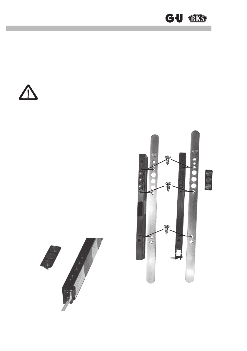
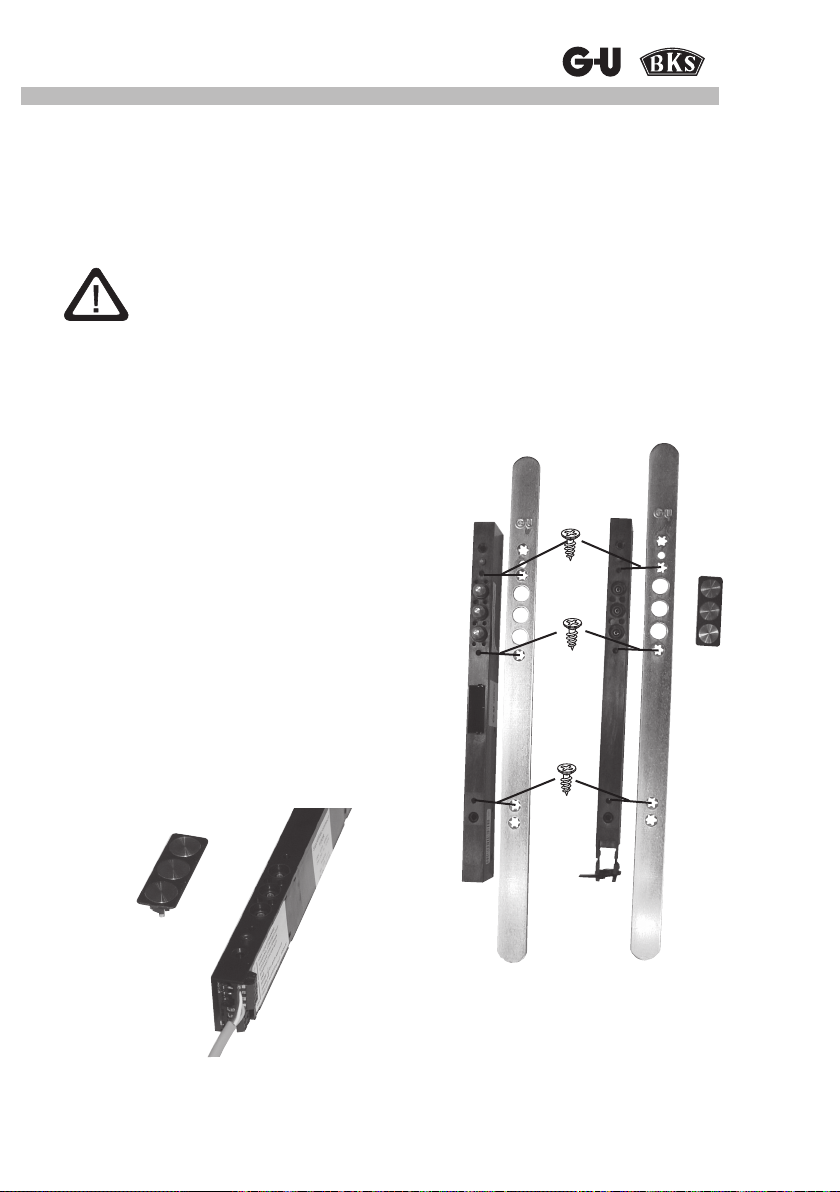
Am SECUREconnect 100R und SECUREconnect 100F jeweils den entsprechenden Stulp mit
den 8 mitgelieferten 4 x 7 Torx-Spezielschrauben befestigen (siehe Beutel).
Die Befestigungsschrauben dürfen nur mit geeignetem
Werkzeug für TORX T20 mit einem max. Drehmoment
von 1,0 Nm angezogen werden.
4.2 Montage Kontaktträger und Kontaktplatte
Nach Montage des Stulps muss am
SECUREconnect 100R der Kontaktträger mit den
3 Kontaktplatten montiert werden.
Die 3 Kontaktplatten sind schon im Kontaktträger
montiert, so dass diese Kontakteinheit nur noch in die
dafür vorgesehene Aufnahme am Stulp hineingedrückt
werden muss.
Die Kontakteinheit rastet leicht ein und lässt sich durch
vorsichtiges Aushebeln mit einem geeigneten Werkzeug
(z.B. Schraubendreher) wieder lösen.
Kontaktträger mit
Kontaktplatte
7
Page 8
SECUREconnect 100
4.3 Falzluft (Kammermaß) einstellen
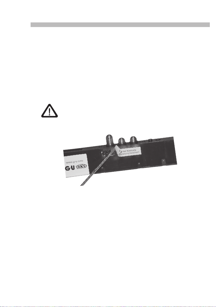
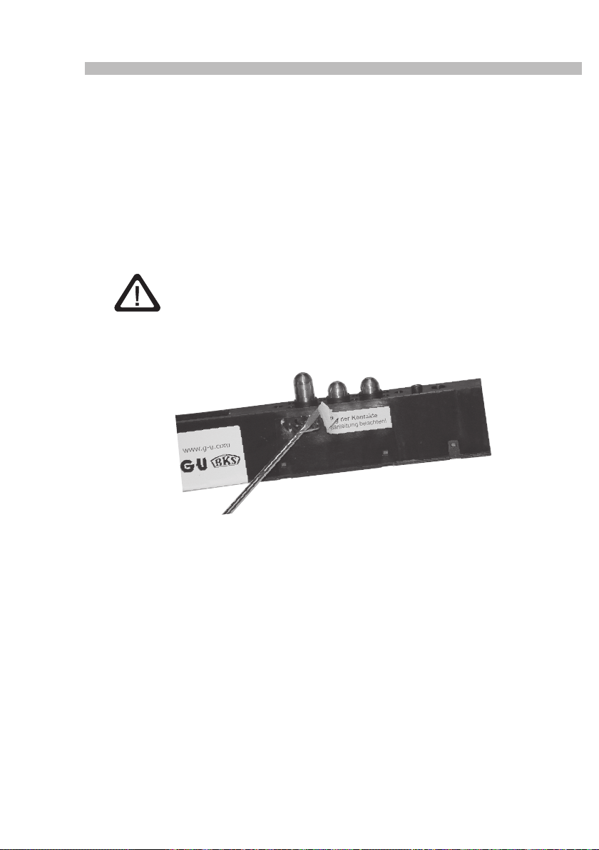
Im Auslieferungszustand ist SECUREconnect 100F für eine Falzluft (Kammermaß) von
0-6 mm eingestellt. Um dieses Maß auf 6-12 mm zu erhöhen, können mittels eines kleinen
Schraubendrehers die seitlich neben den Stößelkontakten bendlichen Begrenzungsklammern
herausgezogen werden. Hierzu ist der Aufkleber „Hubverstellung der Kontakte“ vorsichtig zu
entfernen (später wieder ankleben). Die Stößelkontakten ragen jetzt 12 mm aus dem Gerät.
Bei Falzlufteinstellung 6-12 mm bitte Begrenzungsklammern nicht wieder
einsetzen!
Um SECUREconnect 100F wieder für eine Falzluft von 6 mm zu begrenzen, drücken Sie die
Stößelkontakte bis zum Anschlag hinein und schieben die Begrenzungsklammern wieder ins
Gerät.
Achtung
Verwenden sie keine Falzlufteinstellung von 6-12 mm, wenn die Falzluft
kleiner als 6 mm ist. Dies erhöht die Belastung der Kontakte und verringert
die Lebensdauer des Gerätes.
Aufkleber wegen Schutzwirkung bitte wieder anbringen!
8
Page 9
Strom- und Datenübertrager
4.4 Vorbereitung zum Einbau in die Tür
Je nach Werkstoff der Tür (Holz-, Metall-, Kunststofftür) müssen für den Einbau von
SECUREconnect 100 unterschiedliche und geeignete Befestigungsschrauben verwendet
werden, deren Art und Länge von den verwendeten Prolen abhängig sind.
Der maximale Durchmesser der Schrauben darf jedoch 4,0 mm nicht überschreiten. Die Befestigungsschrauben sollten sich ohne Widerstand an SECUREconnect 100 und Stulp durch das
Gerät schieben lassen.
Ausreichend Platz für eine Kabelschlaufe berücksichtigen.
Achten Sie beim Befestigen des SECUREconnect 100 in der Tür darauf, dass sich der Stulp
(vor allem bei Flachstulpen) nicht verformt.
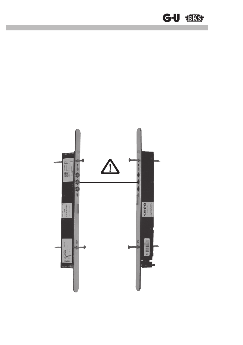
Die Stößelkontakte am SECUREconnect 100F und die Kontaktächen am
SECUREconnect 100R müssen im eingebauten Zustand exakt gegenüberliegen und dürfen
keinen Versatz von mehr als 2 mm haben.
Versatz max. 2 mm
Darstellung für Holztüren.
Bei Metall und Kunststoff wird SECUREconnect 100F über Stulpschrauben befestigt.
Bitte beiliegende Einbauzeichnung Nr. 0-45733-LO beachten.
9
Page 10
SECUREconnect 100
5 Anschlusshinweise
5.1 Leitungsverlegung und elektrischer Anschluss
Achtung:
Bei Installation und Leitungsverlegung sind die Vorschriften und
Normen für SELV Spannung einzuhalten.
Bei der Leitungsverlegung ist unbedingt darauf zu achten, dass die Kabel im Schloss- bzw.
Stulpbereich beim Einbau nicht gequetscht oder beschädigt werden können.
Abzweigdosen sollten für Wartungsarbeiten zugänglich sein. Kabelart, Leitungslängen und
-querschnitte dürfen nur gemäß den Vorgaben ausgeführt werden.
5.2 Allgemeine Beschreibung der Anschlüsse SECUREconnect 100
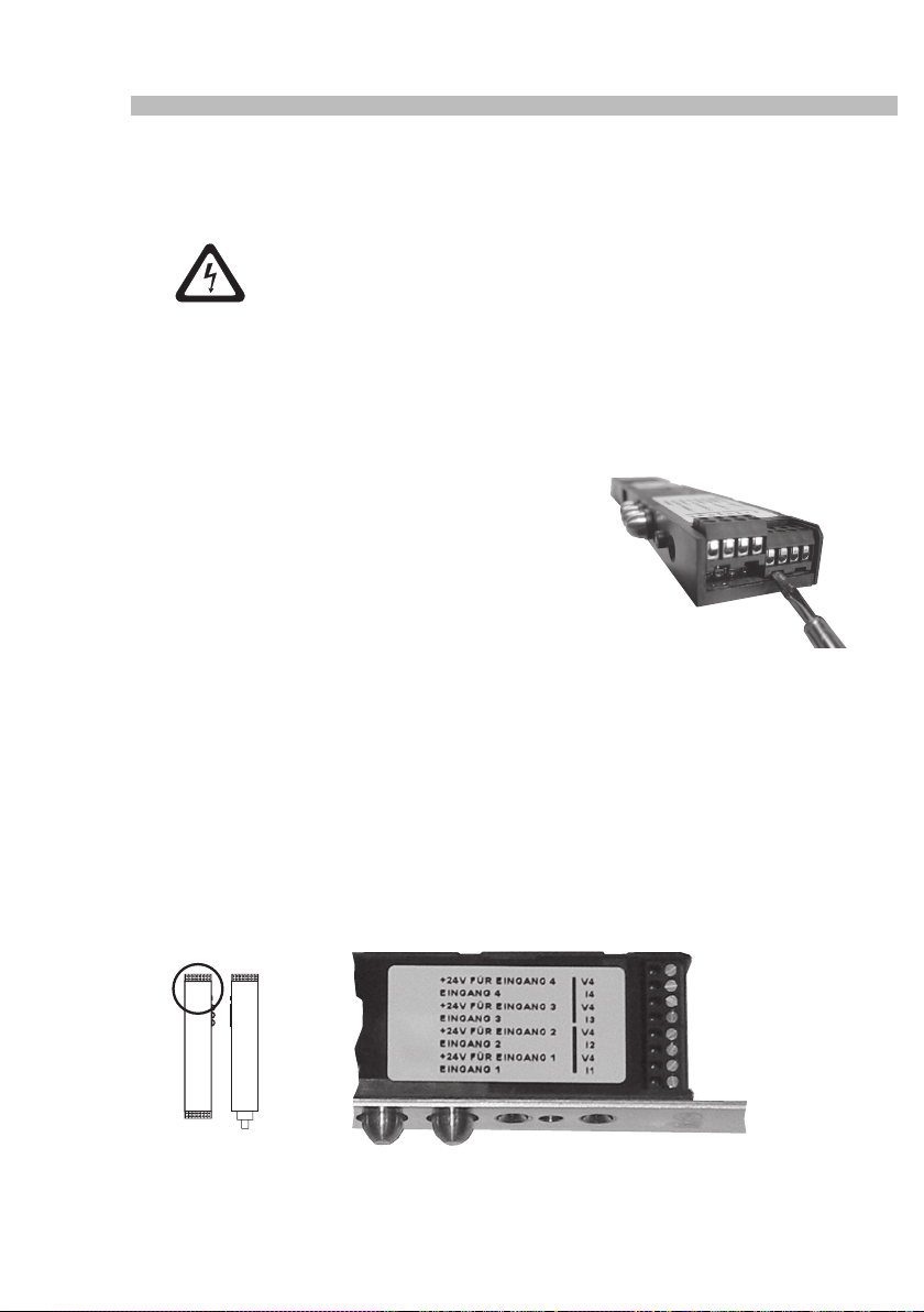
Zum einfacheren Anschluss lassen sich alle
Anschlussklemmen nach vorn abziehen.
5.3 Beschreibung der Anschlüsse SECUREconnect 100F (Flügelteil)
5.3.1 Anschlussklemmen Rückmeldekontakte (I1 - I4 / V4)
Hier werden die Rückmeldekontakte der elektromechanischen oder elektromotorischen Schlösser (soweit vorhanden und benötigt) angeschlossen.
Diese Meldungen werden bei geschlossener Tür an SECUREconnect 100R verschlüsselt
übertragen und über die Relais eines angeschlossenen I/O-Modules I/O10 (Optional) 1:1 potentialfrei als Wechselkontakt ausgegeben.
(siehe Anschlussplan im Anhang)
10
SECUREconnect 100F
Page 11
Strom- und Datenübertrager
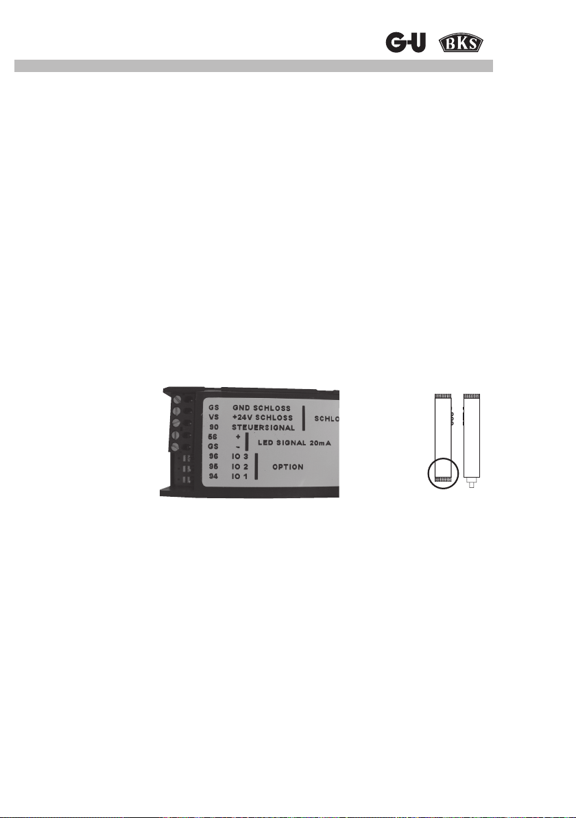
5.3.2 Anschlussklemmen Elektrische Schlösser
An die Klemmen GS, VS und 90 können mechatronische Schlösser von GU BKS angeschlossen werden (siehe jeweils Anschlussplan der verschiedenen Schlösser im Anhang).
5.3.3 Anschlussklemmen LED
An die Anschlussklemmen 56 und GS kann eine LED zur Signalisierung des Öffnungszustandes angeschlossen werden. Dies kann z.B. für einen beleuchteten Türknopf, Stangengriff etc.
genutzt werden. Der Stromausgang ist kurzschlussfest und auf 20 mA begrenzt, so dass die
LED ohne Vorwiderstand angeschlossen werden kann.
Der Stromausgang wird ca. 3 s nach Zurückfahren der Verriegelung solange eingeschaltet,
bis die Verriegelung wieder ausgefahren ist. Bei geöffneter Tür oder Dauerentriegelung jedoch
nicht länger als 15 s.
Die Einschaltdauer ist nicht veränderbar.
5.3.4 Option 1-3
Die Klemmen 94, 95, 96 sind für optionale Anwendungen reserviert.
SECUREconnect 100F
Klemmen 94-96
11
Page 12
SECUREconnect 100
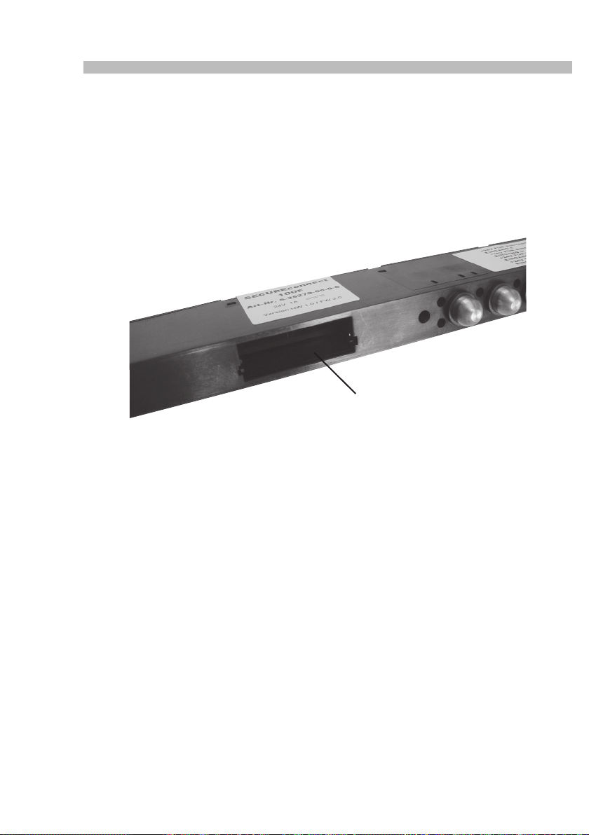
5.3.5 Modulschacht
SECUREconnect 100F kann mit Funktionsmodulen zur Funktionserweiterung ausgestattet
werden, die in den Modulschacht des Gerätes eingeschoben werden.
Der Modulschacht ist für zukünftige Anwendungen reserviert und wird nach Entfernen des
Stulps durch Herausdrehen der 3 Stulpbefestigungsschrauben des SECUREconnect 100F
zugänglich.
Nähere Informationen zum Einbau sind in der Montage- und Bedienungsanleitung der jeweiligen GU Komponente beigelegt.
SECUREconnect 100F
Modulschacht
12
Page 13
Strom- und Datenübertrager
5.4 Beschreibung der Anschlüsse SECUREconnect 100R (Rahmenteil)
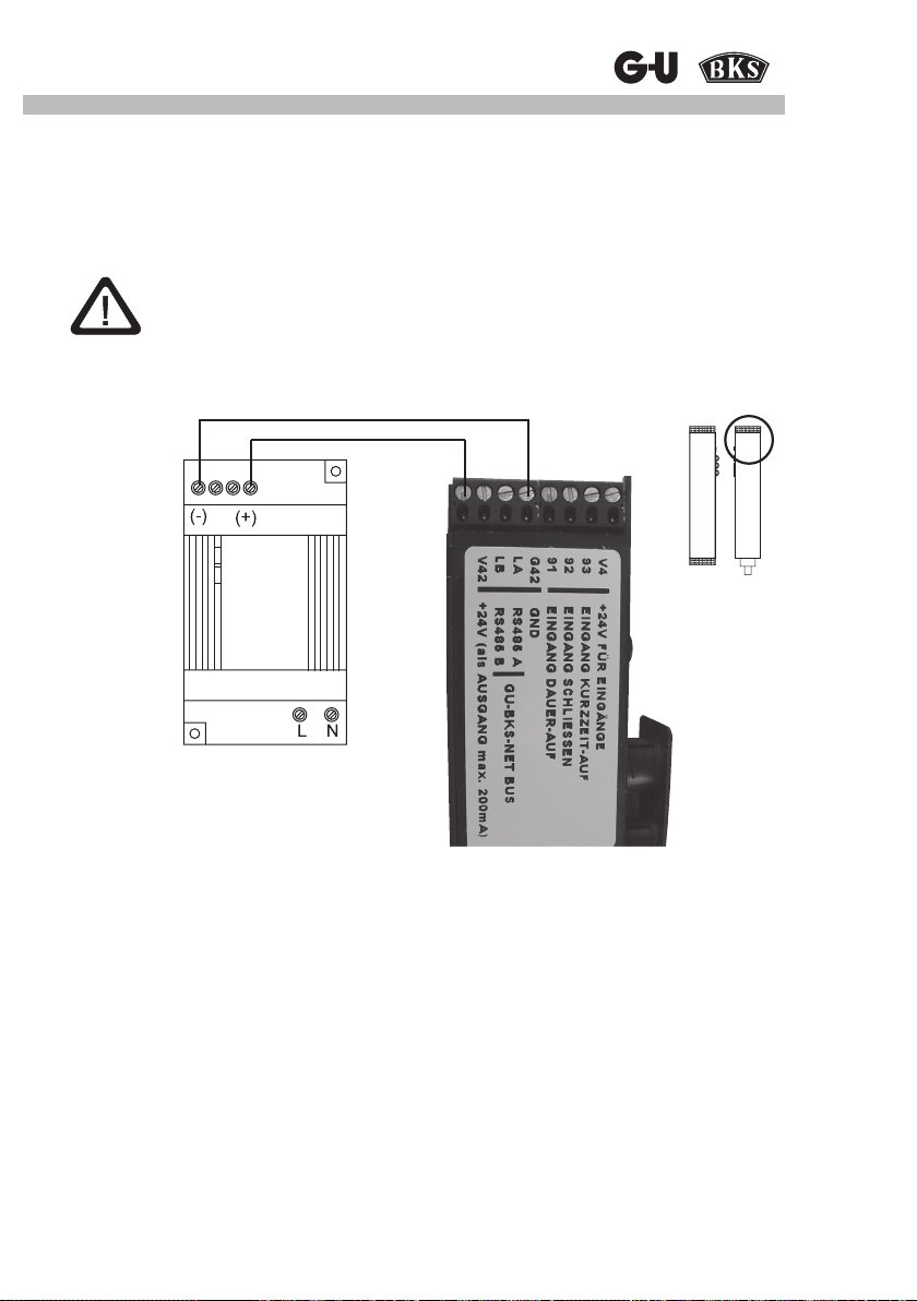
5.4.1 Anschlussklemmen externe 24V DC Spannungsversorgung
An die Klemmen V42 und G42 kann eine externe 24V DC Spannungsversorgung zum Betrieb
des SECUREconnect 100 angeschlossen werden.
Achtung:
Es dürfen nur Spannungsquellen 24V DC nach DIN EN 60950 eingesetzt
werden.
SECUREconnect 100R
*)
Stabilisiertes
Netzteil
230 / 24 V, 1 A
*) Anschluss am „Ausgang“
5.4.2 Anschlussklemmen GU-BKS-NET - Bus
An die Klemmen LA und LB wird der GU-BKS-NET - Bus angeschlossen.
Über diesen BUS kann SECUREconnect 100 mit anderen kompatiblen BUS-Teilnehmern
(z.B. Fluchttürsteuerung FTNT10) kommunizieren.
Nähere Informationen zur Funktion sind der Montage und Bedienungsanleitung zu
GU-BKS-NET beigelegt.
5.4.3 Anschlussklemmen Steuereingänge
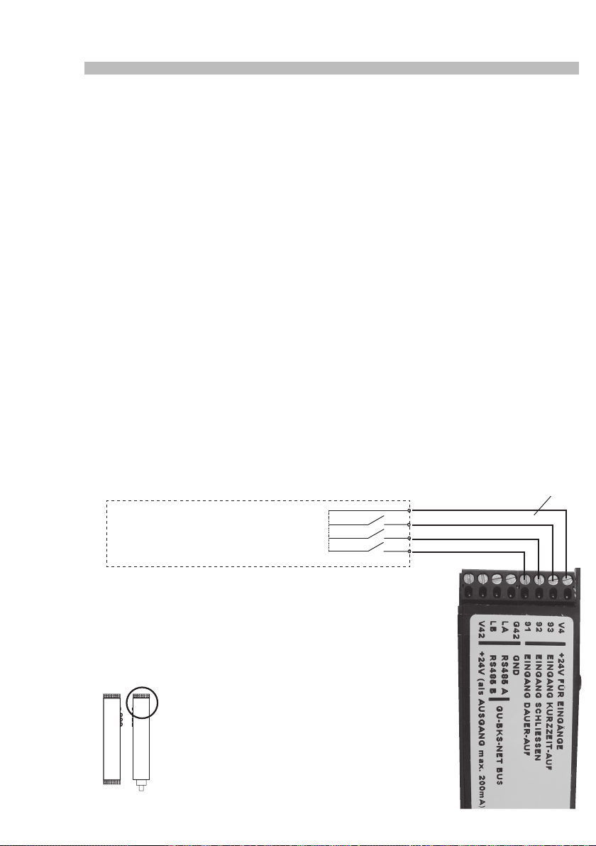
An die Anschlussklemmen V4, 91, 92, 93 werden potentialfreie Kontakte zum Öffnen/ Schließen
der Tür angeschlossen. (Taster, Relais, Zutrittskontrolle, etc.)
13
Page 14
SECUREconnect 100
Ø20
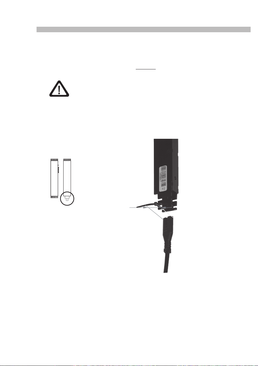
5.4.4 Anschluss 230V AC Spannungsversorgung
SECUREconnect 100 kann mit einer 230V AC Spannung betrieben werden.
Hierzu wird das Netzkabel, nach dem sicheren Verlegen im Türrahmen, im unteren Bereich des
SECUREconnect 100R eingesteckt und zwingend mittels beigelegter Kabelbinder am Gerät
xiert, so dass ein Lösen verhindert wird.
Achtung
Bei Metall- und Kunststofftüren ist zur Leitungseinführung eine
min. Ø 20 mm große Bohrung vorzusehen.
Die Bohrung muss mit der beiliegenden Kabeltülle zum Schutz der Zuleitung versehen werden.
Alle Kanten, über die die Netzzuleitung geführt wird, dürfen nicht scharfkantig und müssen
gratfrei sein.
SECUREconnect 100R
für Bohrung
Wird SECUREconnect 100 an 230V AC angeschlossen, steht an den Klemmen V42 und
G42 für weitere externe Geräte eine Spannung 24V DC, 0,2 A zur Verfügung.
14
Page 15
Strom- und Datenübertrager
6 Inbetriebnahme
Bitte die Montagehinweise in Kapitel 4 beachten!
1. Bauen Sie SECUREconnect 100F in den Türügel ein und schließen Sie das elektrische
Schloss entsprechend den angeführten Anschlussplänen an.
ACHTUNG!
Kabel können beim Eindrehen der Befestigungsschrauben beschädigt
werden!
Empfehlung: Schraube durch das Gerät stecken und Kabel neben der Schraube mit Klebe-
band xieren.
2. Bauen Sie SECUREconnect 100R genau gegenüberliegend in den Türrahmen ein.
Achten Sie darauf, dass beim Schließen der Tür die Stößelkontakte des
SECUREconnect 100F genau auf die Kontaktächen des SECUREconnect 100R treffen
(siehe dazu Montagezeichnung 0-45733-L0).
3. Schließen Sie SECUREconnect 100R an die Betriebsspannung (230V AC oder 24V DC)
an.
6.1 Aufbau der Kommunikation
6.1.1 Codieren
Bei der Inbetriebnahme blinken beide Status LEDs des SECUREconnect 100 nach Anlegen
der Betriebsspannung abwechselnd rot / grün.
Die Status LED am SECUREconnect 100F blinkt grün, wenn die Tür einmal kurze Zeit geschlossen und mit Spannung versorgt wurde. Dies zeigt eine normale Funktionalität an.
In diesem Zustand kommuniziert jedes SECUREconnect 100R mit jedem
SECUREconnect 100F bei voller Funktionalität.
Als erste Sicherheitsstufe erfolgt die Datenübertragung zwischen den Geräten AES-codiert
(abhörsicher verschlüsselt).
Sind SECUREconnect 100R und SECUREconnect 100F für 15 Min. miteinander ununterbrochen verbunden, gehen die Geräte als zweite Sicherheitsstufe eine untrennbare „Partnerschaft“
ein, indem ein Zufallscode generiert und zukünftig zwischen den Geräten ausgetauscht wird.
SECUREconnect 100R und SECUREconnect 100F werden danach keine fremden Flügeloder Rahmenteile mehr akzeptieren.
6.1.2 Trennen
Ein Trennen der Codierung zwischen SECUREconnect 100R und SECUREconnect 100F und
der Austausch einer einzelnen Komponente ist nicht möglich.
Im Fehlerfall werden SECUREconnect 100R und SECUREconnect 100F immer als Paar
ausgetauscht.
15
Page 16
SECUREconnect 100
6.2 LED - Signalisierung
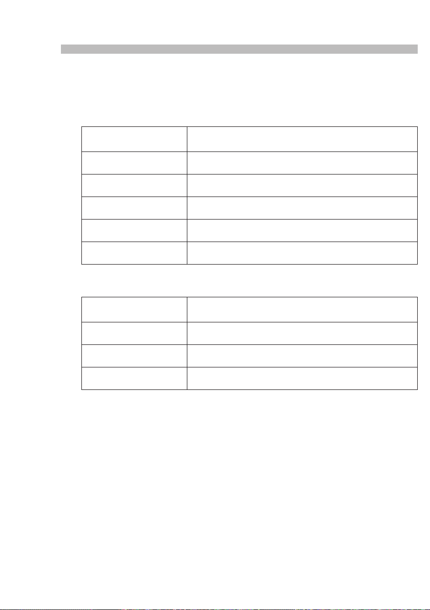
Die LED - Signalisierung am SECUREconnect 100 ist ein wichtiges Hilfsmittel bei der Inbetriebnahme oder Fehlersuche. Sie gibt Auskunft über die verschiedenen Zustände des Gerätes.
6.2.1 Anzeigen am SECUREconnect 100R
LED grün / LED rot
0,5 Hz abwechselnd blinkend
LED grün / LED rot
1 Hz abwechselnd blinkend
LED grün
0,5 Hz blinkend
LED grün
1 Hz blinkend
LED rot
2 Hz blinkend
LED rot
5 Hz blinkend
Anzeige bei geschlossener und geöffneter Tür.
6.2.2 Anzeigen am SECUREconnect 100F
LED grün
1 Hz blinkend
LED grün
0,5 Hz blinkend
LED grün
aus
LED grün
5 Hz blinkend
Anzeige bei geschlossener Tür, sowie bis 15 s nach Öffnen der Tür.
Normalzustand, uncodiert,
keine Kommunikation mit anderen Geräten am GU-BKS NET - Bus
Normalzustand, uncodiert,
Kommunikation mit mindestens einem Gerät am GU-BKS NET - Bus
Normalzustand, codiert,
keine Kommunikation mit anderen Geräten am GU-BKS NET - Bus
Normalzustand, codiert,
Kommunikation mit mindestens einem Gerät am GU-BKS NET - Bus
Temperatur zu hoch
Fehler:
Kurzschluss
Normalzustand, uncodiert
Normalzustand, codiert
Spannungsversorgung zwischen SECUREconnect 100R und 100F ist
längere Zeit unterbrochen
Fehler:
Kurzschluss, Abschaltung, Kondensatoren….
Erläuterung:
5 Hz = 5 x blinken / Sekunde
2 Hz = 2 x blinken / Sekunde
1 Hz = LED 1/2 Sekunde an, 1 x blinken / Sekunde
0,5 Hz = LED 1 Sekunde an
16
Page 17
Strom- und Datenübertrager
6.3 Funktionen mit elektromotorischen Schlössern
(Direktanschluss an die Klemmen V4, 91, 92, 93)
6.3.1 Kurzzeit AUF
Wird ein an den Klemmen 93 / V4 angeschlossener, potentialfreier Kontakt betätigt, wird bei geschlossener Tür an SECUREconnect 100F das Signal zum Öffnen des elektrischen Schlosses
und zum Einfahren der Falle erteilt.
Wird die Tür geöffnet, fährt das elektrische Schloss die Falle nach 3 s wieder aus. Die Tür ist
somit beim Schließen sofort verriegelt.
Bleibt die Tür geschlossen, wird der Fallenriegel nach 2 - 20 s (einstellbar) ausgefahren.
Achtung:
Hier kann es vorkommen, dass die Falle auf das Schließblech auäuft.
Bitte kontrollieren sie den Verschlusszustand der Tür.
Wird ein an den Klemmen 93 / V4 angeschlossener, potentialfreier Kontakt (Tastimpuls) dauerhaft betätigt, bleibt das angeschlossene elektrische Schloss solange geöffnet, wie das Signal
anliegt.
• Wird die Tür geöffnet, fährt das elektrische Schloss die Falle nach 3 s wieder aus.
• Wird die Tür wieder geschlossen, fährt das elektrische Schloss die Falle wieder ein.
6.3.2 Dauer AUF
Wird ein a n den Klemmen 91 / V4 angeschlossener, potentialfreier Kontakt betätigt, wird bei
geschlossener Tür an SECUREconnect 100F das Signal zum Einfahren der Falle erteilt.
Die Falle bleibt dauerhaft eingefahren.
Achtung:
Es erfolgt kein automatischer Wiederverschluss des angeschlossenen elektrischen Schlosses.
Die Anwendung dieser Funktion in Feuerschutz-Türen (DIN 18250) ist untersagt! Dieser führt zum Verlust der Feuerschutzzulassung des Türelementes!
6.3.3 Tür verriegeln
Wird ein an den Klemmen 92 / V4 angeschlossener, potentialfreier Kontakt (Tastimpuls) betätigt, wird bei geschlossener Tür an SECUREconnect 100F das Signal zum Wiederverschließen
des elektrischen Schlosses erteilt.
Achtung:
Hier kann es vorkommen, dass die Falle auf das Schließblech auäuft.
Bitte kontrollieren sie den Verschlusszustand der Tür.
17
Page 18
SECUREconnect 100
6.4 Funktionen mit elektromechanischen Schlössern (EK)
6.4.1 Tür Kurzzeit AUF (Drücker einkuppeln)
Wird ein an den Klemmen 93 / V4 angeschlossener, potenzialfreien Kontakt betätigt, wird bei
geschlossener Tür an SECUREconnect 100F das Signal zum Einkuppeln des Türdrückers
erteilt.
• Bleibt die Tür geschlossen, wird der Türdrücker nach 20 s wieder ausgekuppelt.
• Wird die Tür geöffnet, wird der Türdrücker nach 3 s wieder ausgekuppelt.
• Wird ein an den Klemmen 93 / V4 angeschlossener, potentialfreier Kontakt dauerhaft
betätigt, bleibt der Türdrücker solange eingekuppelt, wie das Signal anliegt (s.o.).
• Wird die Tür geöffnet, wird der Türdrücker nach 3 s wieder ausgekuppelt.
• Wird die Tür wieder geschlossen, wird der Türdrücker wieder eingekuppelt.
6.4.2 Tür Dauer AUF
Wird ein an den Klemmen 91 / V4 angeschlossener, potenzialfreier Kontakt (Tastimpuls) betätigt,
wird bei geschlossener Tür an SECUREconnect 100F das Signal zum Einkuppeln des Türdrückers erteilt.
• Bleibt die Tür geschlossen, bleibt auch der Türdrücker dauerhaft eingekuppelt.
• Wird die Tür geöffnet, wird der Türdrücker nach 3 s wieder ausgekuppelt.
•
Wird die Tür wieder geschlossen, wird der Türdrücker wieder eingekuppelt.
6.4.3 Tür schließen (Drücker auskuppeln)
Wird ein an den Klemmen 92 / V4 angeschlossener, potentialfreier Kontakt betätigt, wird bei
geschlossener Tür an SECUREconnect -F das Signal zum Auskuppeln des Türdrückers erteilt.
Kurzzeit- / AUF z.B. Sprechanlage,
Zutrittskontrolle, Zeitschaltuhr
+ 24 V
Kurzzeit AUF (Impuls)
Schließen (Impuls) / Drücker auskuppeln
Dauer AUF (Impuls)
braun
weiß
gelb
grün
Beiliegendes Anschlusskabel
mit Klemmen
18
Page 19

Strom- und Datenübertrager
6.5 Elektrische Funktionsprüfung
Um einen korrekten Anschluss der kompletten Baugruppe prüfen zu können, sind folgende
Arbeitschritte notwendig:
1. manuelles Schließen der Tür
2. am SECUREconnect 100R die Versorgungsspannung
(z.B. 230V AC mittels EURO-Stecker) anlegen.
3. am SECUREconnect 100R die braune und weiße Ader des Anschlusskabels brücken.
Die Schlossfunktion Kurzeit AUF wird aktiviert und bewirkt eine kurzzeitige Öffnung des elektrischen Schlosses bzw. ein kurzzeitiges Einkuppeln des Außendrückers.
19
Page 20
SECUREconnect 100
7 Anschlusszeichnungen
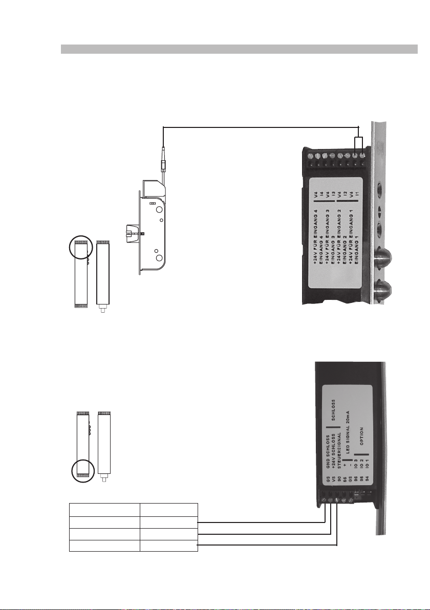
7.1 Fallenriegelüberwachung
Systemkabel zur
Fallenriegelüberwachung
SECUREconnect 100F
7.2 Anschlussplan Secury Automatik mit A-Öffner
Türöffnungszeit bei Impulsansteuerung ca. 2 s (nicht einstellbar).
Türöffnungszeit dauerhaft, solange Ansteuerungssignal ansteht.
Anschlusskabel Signal
Grau (blau) GND (minus)
Braun 24V (plus)
Schwarz Steuerleitung
20
SECUREconnect 100F
Page 21
Strom- und Datenübertrager
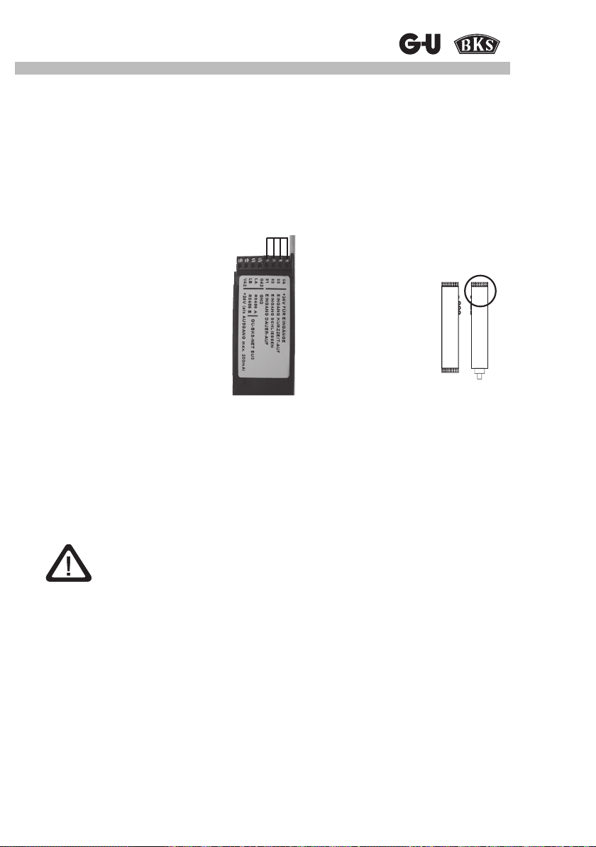
7.3 Ein- und Ausschalten des Tonsignals im A-Öffner
1. Anschluss des A-Öffners an SECUREconnect 100F nach Anschlussplan.
2. SECUREconnect 100R stromlos schalten.
3. Brücken der Klemmen V4, 93, 92, 91.
4. Warten bis SECUREconnect 100F aufhört zu blinken.
5. SECUREconnect 100R und 100F verbinden (z.B. Tür schließen)
6. Spannung am SECUREconnect 100R einschalten.
Es startet nun eine automatische Schaltsequenz, die nach ca. 30 s beendet ist. Während dieser Zeit führt der A-Öffner keine Bewegung aus.
SECUREconnect 100R
Achtung:
SECUREconnect 100R und 100F dürfen während dieser Zeit nicht getrennt
werden. (z.B. Tür öffnen)
7. SECUREconnect 100R stromlos schalten und Brücken entfernen.
8. Warten bis SECUREconnect 100F aufhört zu blinken.
9. Spannung einschalten.
21
Page 22
SECUREconnect 100
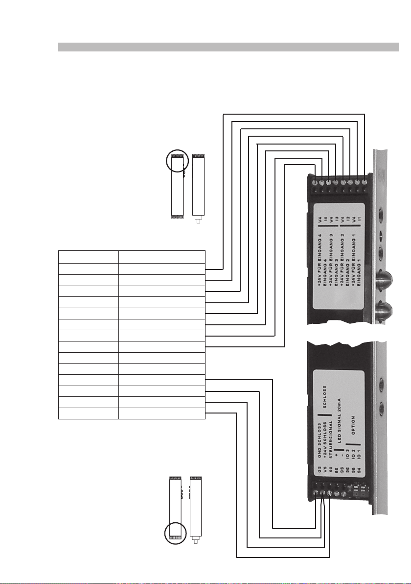
7.4 Anschlussplan Motorschloss
Serie 19 (mit 14 poligem Anschlusskabel)
SECUREconnect 100F
Anschlusskabel Signal
Blau verriegelt COM
Rot verriegelt NO
Schwarz entriegelt COM
Violett entriegelt NO
Grau- rosa Schließbart COM
Rot-blau Schließbart NO
Weiß-grün Funktionsausgang COM
Braun-grün Funktionsausgang NO
Grün nicht belegt
Gelb Funktionseingang
Weiß GND
Braun + 24V
Grau Türkontakt
Rosa Steuerleitung
22
Page 23
Strom- und Datenübertrager
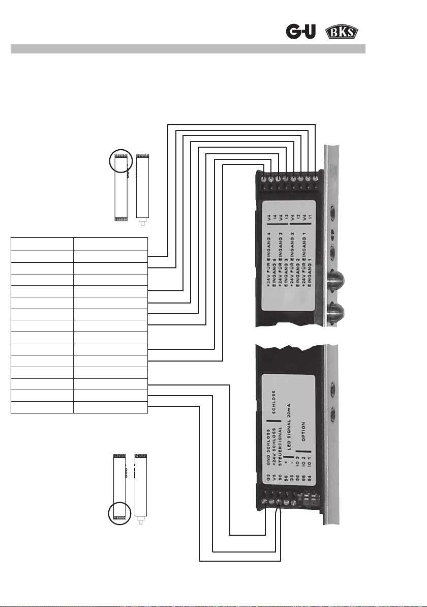
7.5 Anschlussplan EK-Schloss
Serie 19 (mit 14 poligem Anschlusskabel)
SECUREconnect 100F
Anschlusskabel Signal
Blau Verriegelt COM
Grün Verriegelt NO
Grau Verriegelt NC
Rot Schließbart COM
Gelb Schließbart NO
Violett Drücker Seite 1 COM
Rot-blau Drücker Seite 1 NO
Braun-grün Drücker Seite 1 NC
Weiß-grün Drücker Seite 2 COM
Grau-rosa Drücker Seite 2 NO
Schwarz Drücker Seite 2 NC
Weiß GND
Braun +12 - 24V
Rosa Steuerleitung
23
Page 24
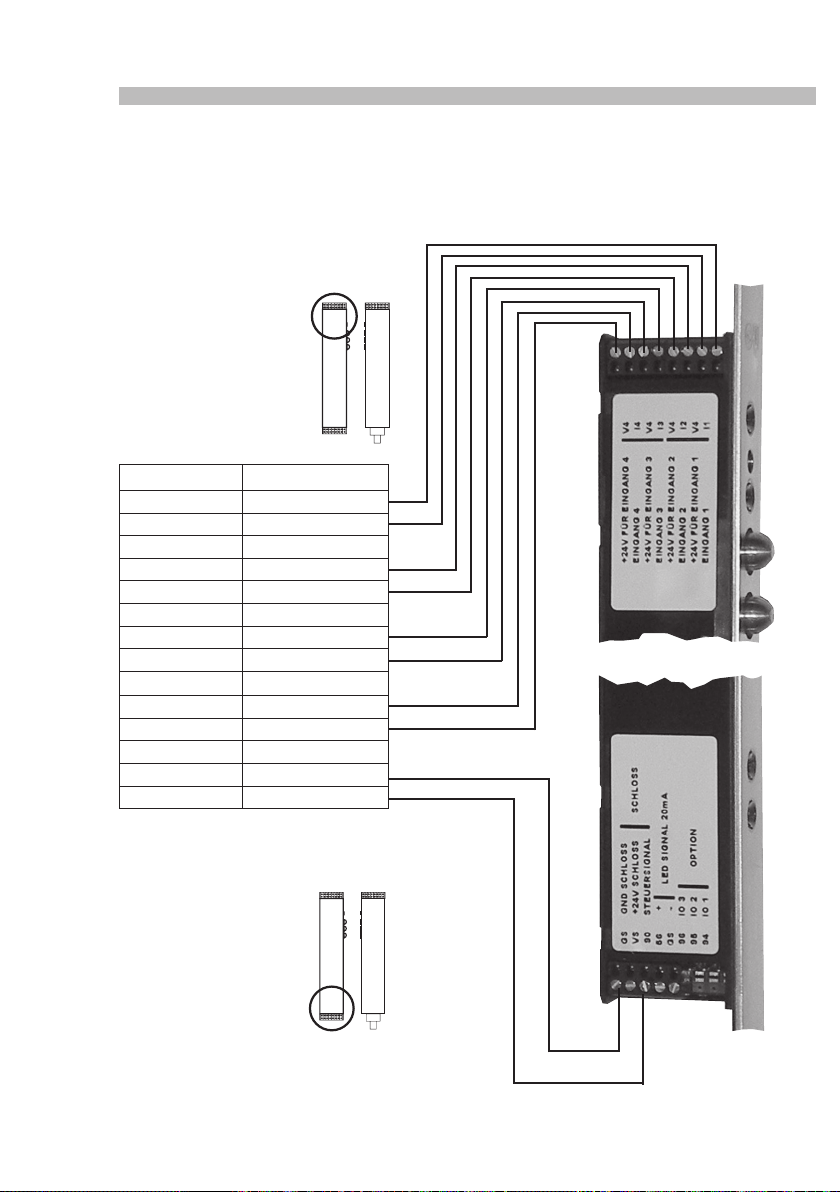
SECUREconnect 100
7.6 Anschlussplan EK-Schloss
Serie 21 (mit 14 poligem Anschlusskabel)
SECUREconnect 100F
Anschlusskabel Signal
Blau Verriegelt COM
Grün Verriegelt NO
Grau Verriegelt NC
Rot Schließbart COM
Gelb Schließbart NO
Rosa Schließbart NC
Violett Drücker Seite 1 COM
Rot-blau Drücker Seite 1 NO
Braun-grün Drücker Seite 1 NC
Weiß-grün Drücker Seite 2 COM
Grau-rosa Drücker Seite 2 NO
Schwarz Drücker Seite 2 NC
Weiß GND
Braun +12 - 24V
24
Page 25
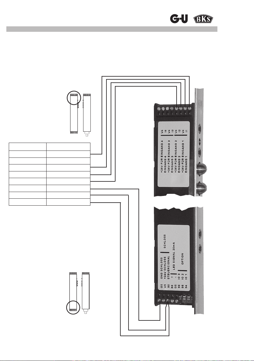
Strom- und Datenübertrager
7.7 Anschlussplan EK-Schloss
Serie 21 (mit 8 poligem Anschlusskabel)
SECUREconnect 100F
Anschlusskabel Signal
Blau Verriegelt COM
Grau Verriegelt NO
Grün Verriegelt NC
Rot Schließbart COM
Gelb Schließbart NO
Weiß GND
Braun +12 - 24V
Rosa Steuerleitung
25
Page 26
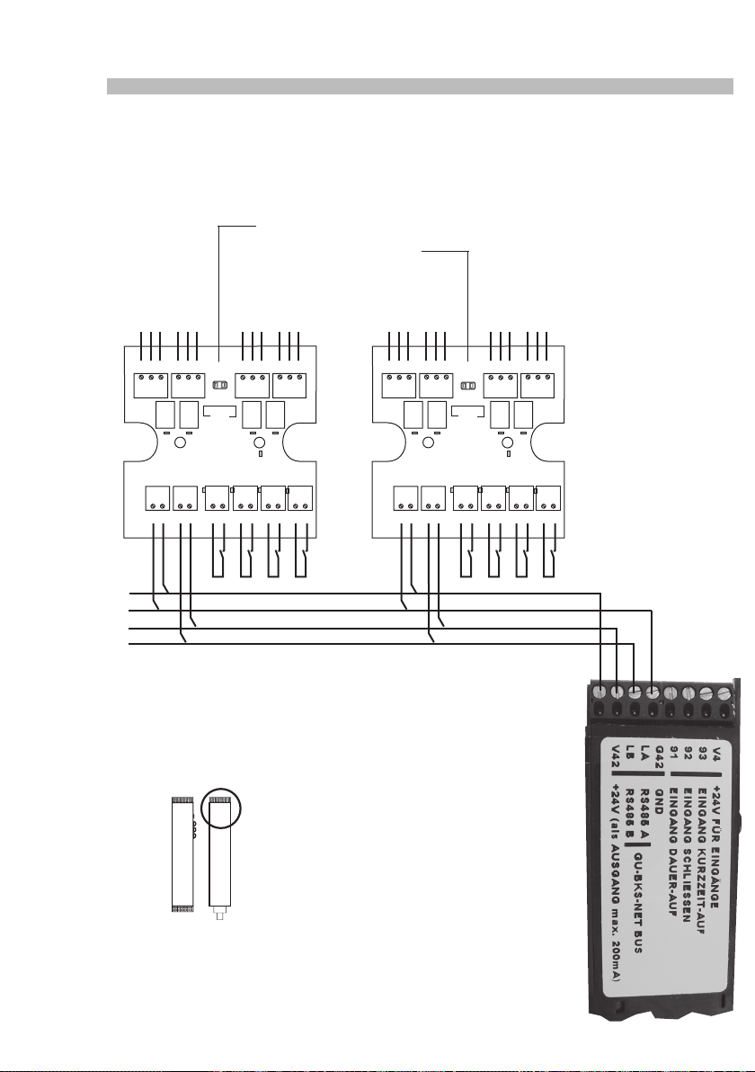
SECUREconnect 100
7.8 Ansteuerung über IO10 Module
Bitte achten Sie darauf, dass sich die Adresseinstellung der IO10 Module unterscheiden.
Adressjumper
Geschlossen: Gerät 1
Offen: Gerät 2
COM
NCNCCOM
NO
NC
COM
NO
NC
COM
NO
NC
COM
NO
NO
NC
COM
NO
NC
COM
NO
NC
COM
NO
61 41 51 61 41 5162 42 52 62 42 5263 43 53 63 43 5364 44 54 64 44 54
Adresse
Service Service
IO10-1
G1 V1 LA LB G1 V1 LA LBV9 I1 V9 I1V9 I2 V9 I2V9 I3 V9 I3V9 I4 V9 I4
Adresse
IO10-2
26
Page 27
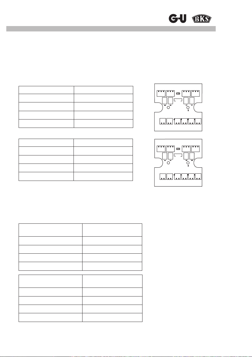
Strom- und Datenübertrager
7.8.1 Eingänge am IO10 Modul
Über die Klemmen LA und LB am SECUREconnect 100R können 2 Stück IO10 -Module angeschlossen werden.
Die Parameter der Ein- und Ausgänge sind entsprechend der GU-BKS-NET Philosophie voreingestellt.
Grundeinstellungen IO10 Adresse 1:
Eingang Funktion
Eingang 1: Klemme I1, V9 Dauer - AUF
Eingang 2: Klemme I2, V9 Schließen
Eingang 3: Klemme I3, V9 Verriegeln mit Vorrang
Eingang 4: Klemme I4, V9 Entriegeln mit Vorrang
Grundeinstellungen IO10 Adresse 2:
Eingang Funktion
Eingang 1: Klemme I1, V9 Entriegeln ohne Vorrang
Eingang 2: Klemme I2, V9 -
Eingang 3: Klemme I3, V9 Kurzzeit - AUF
Eingang 4: Klemme I4, V9 -
61 41 51 62 42 52 6343 53 64 44 54
Service
G1 V1 LALB V9 I1 V9 I2 V9 I3 V9 I4
61 41 51 62 42 52 6343 53 64 44 54
Service
G1 V1 LALB V9 I1 V9 I2 V9 I3 V9 I4
7.8.2 Ausgänge am IO10 Modul
Der Status der Eingänge (SECUREconnect 100F) wird direkt an die Relais des IO10-Moduls
ausgegeben.
Grundeinstellungen
Eingang
(SECUREconnect 100F)
Eingang 1: Klemme I1, V4 Relais 1: Klemme 41, 51, 61
Eingang 2: Klemme I2, V4 Relais 2: Klemme 42, 52, 62
Eingang 3: Klemme I3, V4 Relais 3: Klemme 43, 53, 63
Eingang 4: Klemme I4, V4 Relais 4: Klemme 44, 54, 64
Eingang
(SECUREconnect 100F)
Eingang 1: Klemme I1, V4 Relais 1: Klemme 41, 51, 61
Eingang 2: Klemme I2, V4 Relais 2: Klemme 42, 52, 62
Eingang 3: Klemme I3, V4 Relais 3: Klemme 43, 53, 63
Eingang 4: Klemme I4, V4 Relais 4: Klemme 44, 54, 64
Ausgang
IO10 Adresse 1
Ausgang
IO10 Adresse 2
27
Page 28

SECUREconnect 100
8 Inspektions- und Wartungsarbeiten, Ersatzteile
Das SECUREconnect 100 darf nur mit herstellereigenen Netzteilen oder 230V AC betrieben
werden.
Bei Verwendung von Fremdfabrikaten besteht keinerlei Haftungs-, Gewährleistungs- oder
Serviceleistungsanspruch.
Werden Ersatzteile oder Erweiterungen benötigt, so dürfen ausschließlich Originalteile des
Herstellers verwendet werden.
Wartungs- und Instandsetzungsarbeiten dürfen nur von Fachkräften ausgeführt werden, welche
vom Hersteller geschult bzw. autorisiert sind.
Schlösser:
Die Betriebsbereitschaft des Verschlusssystems ist regelmäßig zu prüfen. Hierzu müssen die
Befestigungspunkte überprüft- und die Schrauben ggf. nachgezogen werden. Die mechanischen Eigenschaften des Schlosses (Schlüssel- bzw. Drückerbedienung / Fallenriegel) dürfen
nicht durch Verschmutzung beeinträchtigt werden und müssen ebenfalls regelmäßig gewartet
und geölt werden (z.B. BKS Pegespray).
SECUREconnect 100
SECUREconnect 100 ist wartungsfrei.
Es empehlt sich, die Kontakte gelegentlich mit einem weichen, trockenen Tuch zu reinigen.
Verwenden Sie niemals Öl- oder Silikonhaltige Schmier- oder Reinigungsmittel.
9 Entsorgung
Das Bauteil / Gerät enthält elektronische Teile und muss entsprechend den gesetzlichen
Bestimmungen entsorgt werden.
28
Page 29
SECUREconnect 100
Power and Data Transmission Unit
Mounting and Operating Instructions
Techncial Data Sheet
29
Page 30

SECUREconnect 100
Contents
1 Information 31
1.1 General advice 31
1.2 Delivery contents 31
2 Technical description 32
2.1 Field of application 32
2.2 Schematic view 33
3 Safety advice 34
4 Mounting preparations 35
4.1 Mounting the face plates 35
4.2 Mounting the contact holder with contact plates 35
4.3 Regulating the rebate clearance 36
4.4 Installation in the door 37
5 Wiring advice 38
5.1 Wiring and electrical connection 38
5.2 SECUREconnect 100 terminals 38
5.3 Connection terminals of SECUREconnect 100F
(leaf-side component) 38
5.4 Connection terminals of SECUREconnect 100R
(frame-side component) 41
6 Start-up 43
6.1 Establishing communication 43
6.2 LED signalling 44
6.3 Functions with motor-driven locks 45
6.4 Function with electromechanical locks ('EK') 46
6.5 Electrical function test 47
7 Connection diagrams 48
7.1 Latchbolt monitoring 48
7.2 Connection diagram Secury Automatik with A-opener 48
7.3 Switching the A-opener's acoustic signal on and off 49
7.4 Connection diagram of motor-driven lock
Series 19 (with 14-wire connecting cable) 50
7.5 Connection diagram of ‘EK‘ lock
Series 19 (with 14-wire connecting cable) 51
7.6 Connection diagram of ‘EK‘ lock
Series 21 (with 14-wire connecting cable) 52
7.7 Connection diagram of ‘EK‘ lock
Series 21 (with 8-wire connecting cable) 53
7.8 Control via IO10 modules 54
8 Inspection and maintenance works, replacement parts 56
9 Disposal 56
30
Page 31

Power and Data Transmission Unit
1 Information
Thank you for having decided to purchase SECUREconnect 100, a safe and compact power
and data transmission unit intended for use with motor-driven or electromechanical locking
systems.
1.1 General advice
This manual contains important advice which must be followed in order to prevent hazard,
ensure the reliable functioning and long service life of SECUREconnect 100, and to reduce
downtimes and repair cost.
The instructions must be read carefully by every person handling SECUREconnect 100, e.g.,
during
• Installation and electrical connection
• Start-up and maintenance
It is essential that the information given in this manual, especially the chapters concerned with
safety, should be observed.
After installation, the instruction manual must be handed over to the operating company/user
who should read it carefully before operating the unit the rst time and keep it for later service
and maintenance. Please point out the necessity to read these instructions thoroughly to all
users and responsible persons.
1.2 Delivery contents
The package contains:
Delivery contents
Qty. Designation
1 pc. SECUREconnect 100R (component for door frame)
1 pc. SECUREconnect 100F (component for door leaf)
4 m 230V mains cable with Europlug
4 m Connecting cable with input terminals
1 pc. SECUREconnect 100R plastic contact holder with 3 contact plates
1 bag 8 fastening screws for attachment of face plates
1 pc. Mounting and Operating Instructions
1 pc. Installation instructions
1 rubber grommet, 1 cable tie for strain relief
31
Page 32

SECUREconnect 100
2 Technical description
2.1 Field of application
The SECUREconnect 100R and -F components are designed for vertical installation in the the
frame and the door leaf, respectively.
It is not permitted to operate the unit in exterior gate or door assemblies where ambient conditions require a higher protection class than IP 40.
SECUREconnect 100 must not be used for purposes other than the intended use (see
chapter 1 Information).
'Intended use' comprises the observance of the manufacturer's operating and service instructions which is essential for the avoidance of damage and injury.
The companies G-U and BKS exclude any liability for damage arising from changes made on
the lock or on the lock connection without their consent.
• Suitable for installation in timber, PVC, and metal door assemblies with the use of prolespecic screw-on type face plates.
• Short-circuit proof power transmission between door frame and leaf.
• Encrypted data transmission.
All deliveries are made on the basis of the General Terms and Conditions of the company GU.
SECUREconnect 100R for installation in the door frame
• Power and data transmission unit for motor-driven or electromechanical locking systems
from GU and BKS.
• Communication interface to the GU-BKS-NET bus, output of lock statuses to IO10 (relay
box).
• Status indicator LEDs.
• Optional voltage supply of 24 V DC or 230V
SECUREconnect 100F for installation in the door leaf
• Power and data transmission unit for motor-driven or electromechanical locking systems
from GU and BKS.
• Long-life tappet contacts (no need of a cable duct).
• Any door opening angle possible
• Unhindered hinging and unhinging of door leaf.
• 4 inputs for transmission of lock statuses
• Power output 20 mA for connection of LED signalling 'open'.
• Status indicator LEDs.
• Compartment for extension modules for possible future applications.
• Once installed, the unit is maintenance-free.
Operating parameters
Supply voltage 230V AC 50/60 Hz 0.25 A or 24V DC stabilised 1.0 A
IP Protection class IP 40
Protection system II
Ambient temperature -20 °C … +45 °C
32
Page 33
Power and Data Transmission Unit
2.2 Schematic view
J-Y(ST) Y2x2x0.6
For various
control options
see chapter 5.
SECUREconnect 100F
SECUREconnect 100R
IO10
Potential-free control
contact, e.g. pushbutton,
intercom, access control,
timer switch.
For various control
options see chapter 6.
Connecting cable with input terminals
For metal and PVC doors use rubber
grommet enclosed in package.
IO10
Door leaf with SECUREconnect 100F
(Position and cable route)
For detailed recess dimensions see drawing
0-45733-L0.
Frame jamb with SECUREconnect 100R
Position and cable route
(230V AC, 24V DC, BUS, control line, IO10)
33
Page 34

SECUREconnect 100
3 Safety advice
It is necessary to ensure that only trained specialists (for the denition thereof see EN 50110-1,
DIN VDE 0105 or IEC 60364) are charged with jobs related to the product (planning, transport,
assembly, installation, start-up, maintenance, repair, dismantling).
Moreover, it is necessary to ensure that the documents required for installation, start-up,
operation, maintenance and repair of the product are made available to the specialists and
observed by them duly.
Danger !
Installation works involving the use of electrical equipment are
dangerous.
Insufcient wire cross sections may cause a re. Therefore it is
important to always observe the specied cross sections.
Connections to a 230V mains are dangerous to life !
The installation of electrical components must be carried out by trained
electricians only. Non-observance of the installation advice may result in re
and other hazards.
• Observe operating instructions before connection to the mains.
• Relieve supply line from strain by an appropriate means.
• Do not damage connecting cables.
• Use enclosed rubber grommet on cable outlet from prole.
• Observe standards and regulations for extra-low voltage (SELV) during installation and
laying of cables.
• By no means switch a 'permanent OPEN' contact when using the unit on smoke and re
protection doors (DIN 18250) ! This will nullify the door assembly's re approval.
• The door leaf component of SECUREconnect has an integral energy storage ensuring
that in the event of a power failure during short-time 'OPEN', the retracted latchbolts of all
mechatronic G.U-BKS locks will eject to be ready for locking. This provides for safe and
reliable door locking in the event of a re.
• SECUREconnect 100R features an internal 2 A fuse which is not accessible from outside
and not suitable for being exchanged. Opening the device will damage it and nullify its
warranty.
• Disconnecting the unit from the mains is done by pulling the power plug from the
socket.
The socket must be freely accessible.
If SECUREconnect 100 is connected to the electricity supply permanently, it is necessary
to provide for switch off by means of a suitable and appropriately marked device on the
building's distribution board, e.g. a switch, fuse, or automatic cutout.
This manual is part of the product and must remain with the end user.
34
Page 35
Power and Data Transmission Unit
4 Mounting preparations
General mounting advice
The electronic components should be installed with utmost care since chafed or defective cables, damaged contacts etc. may seriously affect the safety of the system and cause its failure.
Ensure that all components are in faultless state before mounting them.
It is imperative to observe the attached assembly drawing!
4.1 Mounting the face plates
Attach SECUREconnect 100R and SECUREconnect 100F to the corresponding face plate,
each, using the special 4 x 7 Torx screws included in the bag (8 altogether).
Tighten screws with a max. torque of 1.0 Nm using a TORX T20 suitable tool only.
4.2 Mounting the contact holder with contact
plates
After having attached the face plate, mount the contact
holder with the 3 contacts to SECUREconnect 100R.
The 3 contact plates are rmly attached to the contact
holder, so all you have to do is press the unit through the
face plate bores into the provided jacks, you will feel the
part snap in lightly.
If necessary, the contact unit can be levered out again
carefully using an appropriate tool, e.g. an screw driver.
Contact holder with
contact plates
35
Page 36
SECUREconnect 100
4.3 Regulating the rebate clearance
The ex-factory setting of SECUREconnect 100F regarding the rebate clearance is 0 - 6 mm.
For increasing this value to 6 - 12 mm, it is possible to pull out the restricting brackets on the
side of the tappet contacts using a small screwdriver. In doing so, the adhesive label "Hubverstellung der Kontakte" (adjustment of contact travel) must be removed carefully and re-attached
afterwards. The tappet contacts now protrude 12 mm from the device.
Do not reinsert the restriction brackets with the rebate clearance set
to 6 - 12 mm !
If you wish to limit SECUREconnect 100F to a rebate clearance of 6 mm again, press back the
tappet contacts until stop and reinsert the restricting brackets.
Attention
Do not adjust to 6 - 12 mm rebate clearance if the clearance is smaller than
6 mm. This would increase the strain on the contacts and reduce the service
life of the device.
36
Reattach the adhesive label for protection !
Page 37
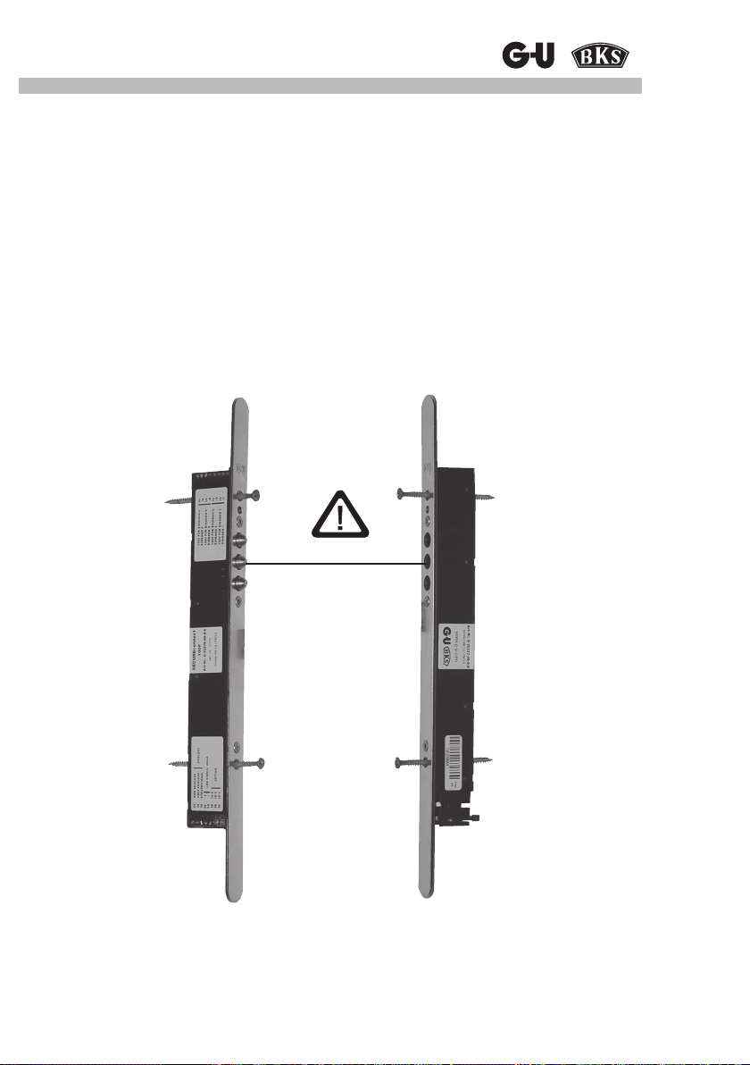
Power and Data Transmission Unit
4.4 Installation in the door
Depending on the door material (timber, metal, PVC), different fastening screws must be used
for the installation of SECUREconnect 100; type and length of the screws vary according to the
door prole used.
It is important, however, that the max. screw diametre does not exceed 4.0 mm. The fastening screws should allow for being inserted through the face plate and SECUREconnect 100
without any resistance.
Ensure that there is sufcient space for a cable loop.
Be careful to not deform the face plate when fastening SECUREconnect 100 to the door (this
refers especially to at face plates).
In installed condition, the tappet contacts of SECUREconnect 100F and the contact surfaces of
SECUREconnect 100R must be exactly aligned, the maximum tolerable offset is 2 mm.
Max. offset 2mm
Figure shows installation in timber doors.
In the case of metal and PVC doors, SECUREconnect 100F is fastened by the face
plate screws.
Please consider enclosed installation drawing 0-45733-LO.
37
Page 38
SECUREconnect 100
5 Wiring advice
5.1 Wiring and electrical connection
Attention:
Observe standards and regulations for extra-low voltage (SELV)
during installation and laying of cables.
The cables must be laid in such a way that they cannot be squeezed in or dammaged in the
area of the lock forend during installation.
Distribution boxes must be accessible for maintenance work. Cable types, lengths, and cross
sections must conform to the specications.
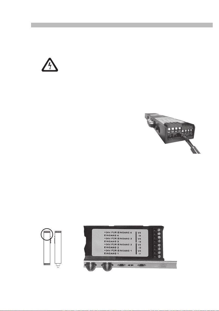
5.2 SECUREconnect 100 terminals
To facilitate connection, all terminals can be
disconnected from the front.
5.3 Connection terminals of SECUREconnect 100F
(leaf-side component)
5.3.1 Terminals for monitoring contacts (I1 - 14 / V4)
This is where the door monitoring contacts of the electromechanical or motor-driven locks (if
provided) are connected.
With the door closed, the feedback signals are transmitted to SECUREconnect 100R (frame
component) in an encrypted way and put out 1:1 to a potential-free changeover contact via the
relays of a connected I/O module I/O10 (optional).
(see connection diagram in the appendix)
SECUREconnect 100F
38
Page 39
Power and Data Transmission Unit
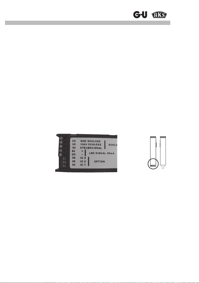
5.3.2 Connection terminals for electrical locks
The terminals GS, VS, and 90 are provided for the connection of mechatronic locks from
G.U-BKS (for particular connection diagrams see appendix).
5.3.3 Connection terminals for LED
Terminals 56 and GS are provided for the connection of an LED signallingunlocked status.
This is useful, e.g., for illuminated door knobs or push bars. The power output is short circuit
protected and limited to 20 mA which allows the LED to be connected without pre-resistor.
Approx. 3 s after door release, the power output is switched on for the duration of release,
however, not longer than 15 s regardless of whether in short-time OPEN or permanent OPEN
mode.
The switch-on time cannot be changed.
5.3.4 Options 1-3
Terminals 94, 95, and 96 are reserved for optional applications.
SECUREconnect 100F
Terminals 94-96
39
Page 40
SECUREconnect 100
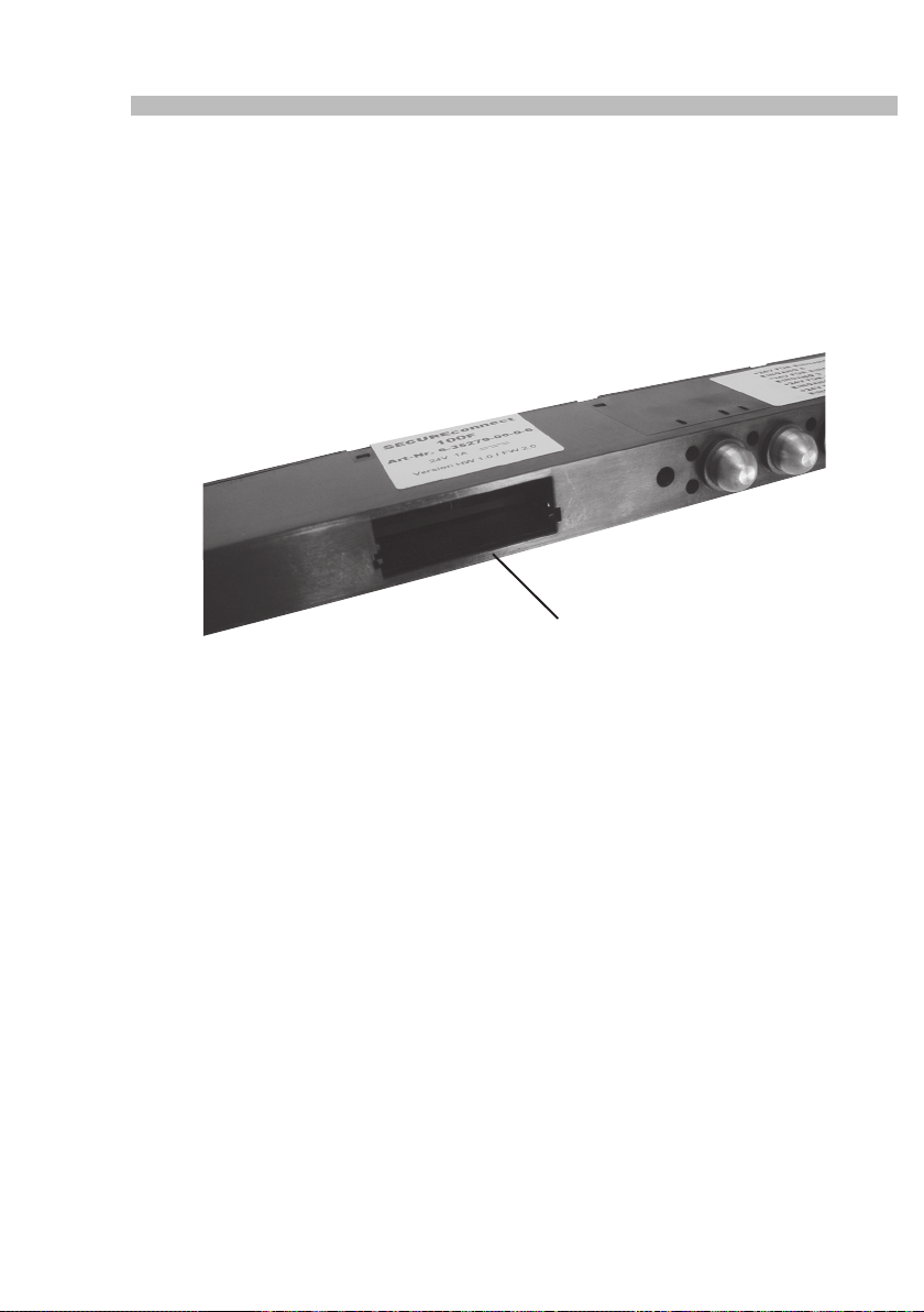
5.3.5 Module compartment
To extend SECUREconnect 100F for further functions, it is possible to insert extension modules into the module compartment of the device.
Provided for future applications, this compartment is accessible after removing the face plate
from SECUREconnect 100F by turning out the fastening screws.
Further installation details are to be taken from the mounting and operating instructions of the
respective GU device.
SECUREconnect 100F
Module compartment
40
Page 41
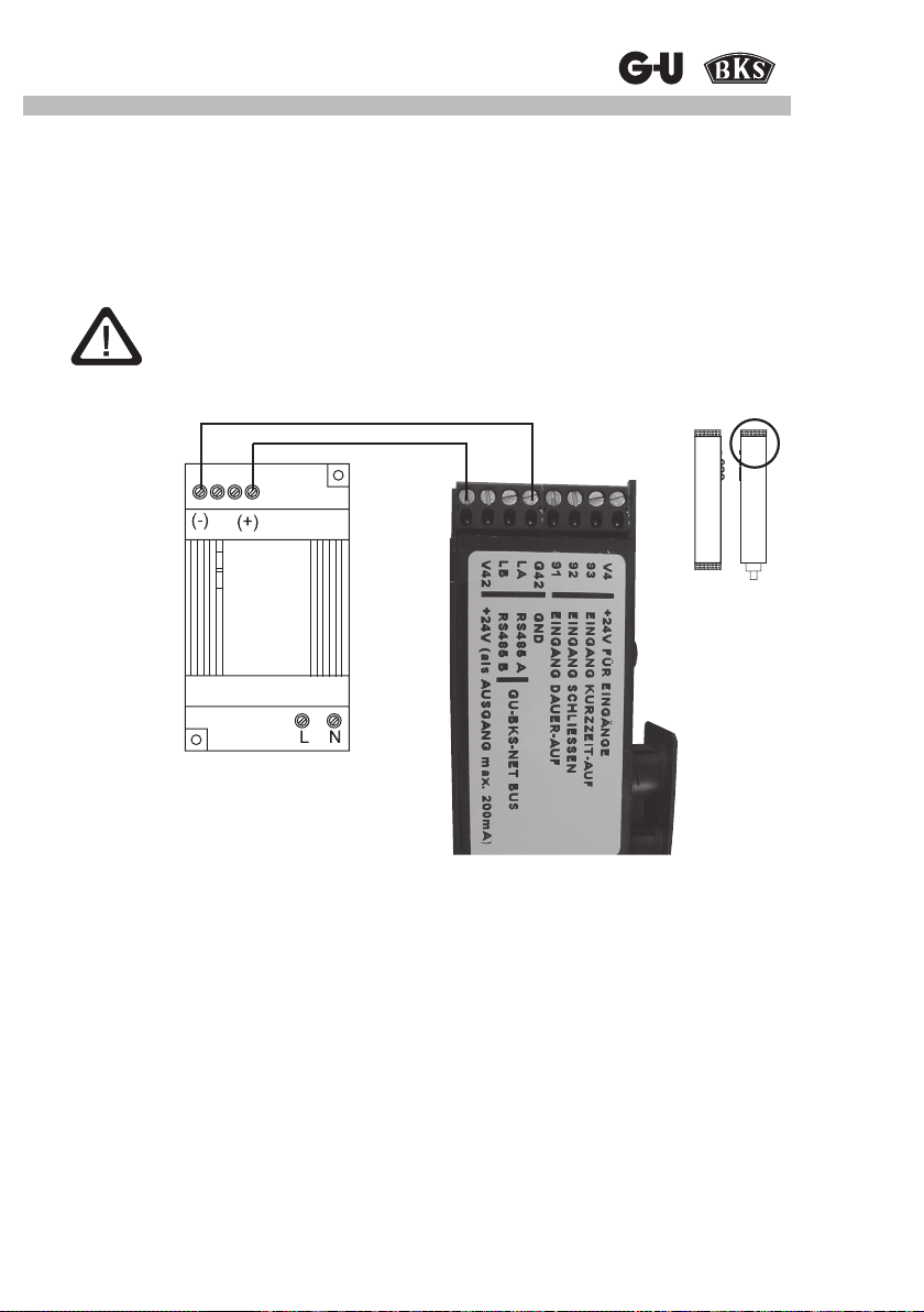
Power and Data Transmission Unit
5.4 Connection terminals of SECUREconnect 100R
(frame-side component)
5.4.1 Terminals for external 24V DC voltage supply
The terminals V42 and G42 are provided for the connection of an external 24V DC voltage
supply to operate SECUREconnect 100
Attention:
Only 24 V DC voltage sources in accordance with EN 60950 may be used.
SECUREconnect 100R
*)
Stabilized
power supply
230 / 24 V, 1 A
*) Connecting at output „Ausgang“
5.4.2 Connection terminals for GU-BKS-NET bus
Terminals LA and LB are assigned for the connection of the GU-BKS-NET bus.
This bus allows SECUREconnect 100 to communicate with other compatible bus participants
(e.g. escape door control unit FTNT10).
Further functional details are to be taken from the GU-BKS-NET installation and operating
instructions.
5.4.3 Connection terminals for control inputs
The terminals V4, 91, 92, 93 are provided for potential-free contacts required to open and close
the door. (Pushbutton, relays, access control etc.)
41
Page 42
SECUREconnect 100
Ø20
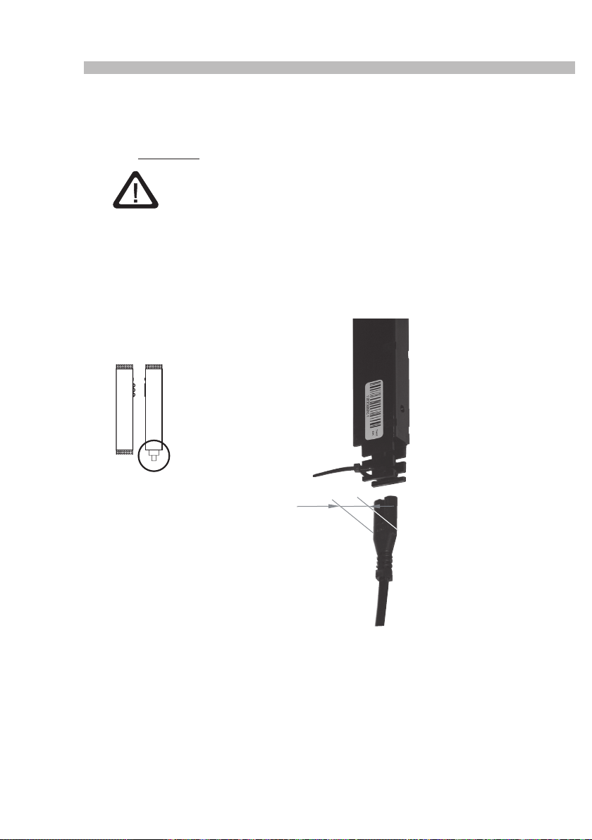
5.4.4 Connecting a 230V AC voltage supply
SECUREconnect 100 is suited for operation with 230V AC voltage.
The mains cable is plugged in at the bottom side of SECUREconnect 100R and must be
xed by all means with the attached cable tie to prevent it from coming loose.
Attention
With metal and PVC doors, it is necessary to drill a cable inlet with a
minimum diametre of 20 mm.
The borehole must be tted with the enclosed rubber grommet to protect the lead.
All edges touched by the mains cable must be unsharp and free of burrs.
SECUREconnect 100R
for
Ø20 bore
If SECUREconnect 100 is connected to 230V AC, a 24V AC 0.2 A voltage for external devices
will be available at terminals V42 and G42.
42
Page 43
Power and Data Transmission Unit
6 Start-up
Please observe the mounting advice given in chapter 4!
1. Install SECUREconnect 100F in the door leaf and connect the electrical lock according to
the particular connection diagram.
ATTENTION!
Cables may be damaged when turning in the fastening screws.
We recommend: Insert screw through device and x cable beside the screw with adhesive
tape.
2. Install SECUREconnect 100R in the door frame exactly on the opposite side.
Ensure that the tappet contacts of SECUREconnect 100F exactly coincide with the contact surfaces of SECUREconnect 100R as the door closes (see also installation drawing 0-45733-L0).
3. Connect SECUREconnect 100R to the operating voltage supply (230V AC or 24V DC).
6.1 Establishing communication
6.1.1 Coding
At start-up, the two status LEDs of SECUREconnect 100 will be ashing alternately red and
green as soon as the operating voltage has been applied.
The status LED on SECUREconnect 100F ashes green as soon as the door has been closed
once for a short time and supplied with voltage. This indicates normal functioning.
At this stage, the two SECURE connect 100 components are not yet coupled, so a SECURE-
connect 100R component could communicate openly and function perfectly with any SECURE-
connect 100F component.
The rst level of security consists in the fact that the exchange data between the two components are AES-encrypted.
As a second level of security, SECUREconnect 100R and SECUREconnect 100F – after having been connected with each other for 15 minutes – enter into an inseparable "partnership" by
generating a random code which will be exchanged between the two components later on.
Afterwards SECUREconnect 100R and SECUREconnect 100F will no longer accept any other
frame or leaf components.
6.1.2 Separation
The code uniting SECUREconnect 100R and SECUREconnect 100F cannot be changed, this
means exchanging just one component is not possible.
In the event of failure, SECUREconnect 100R and SECUREconnect 100F must always
exchanged as a pair.
43
Page 44
SECUREconnect 100
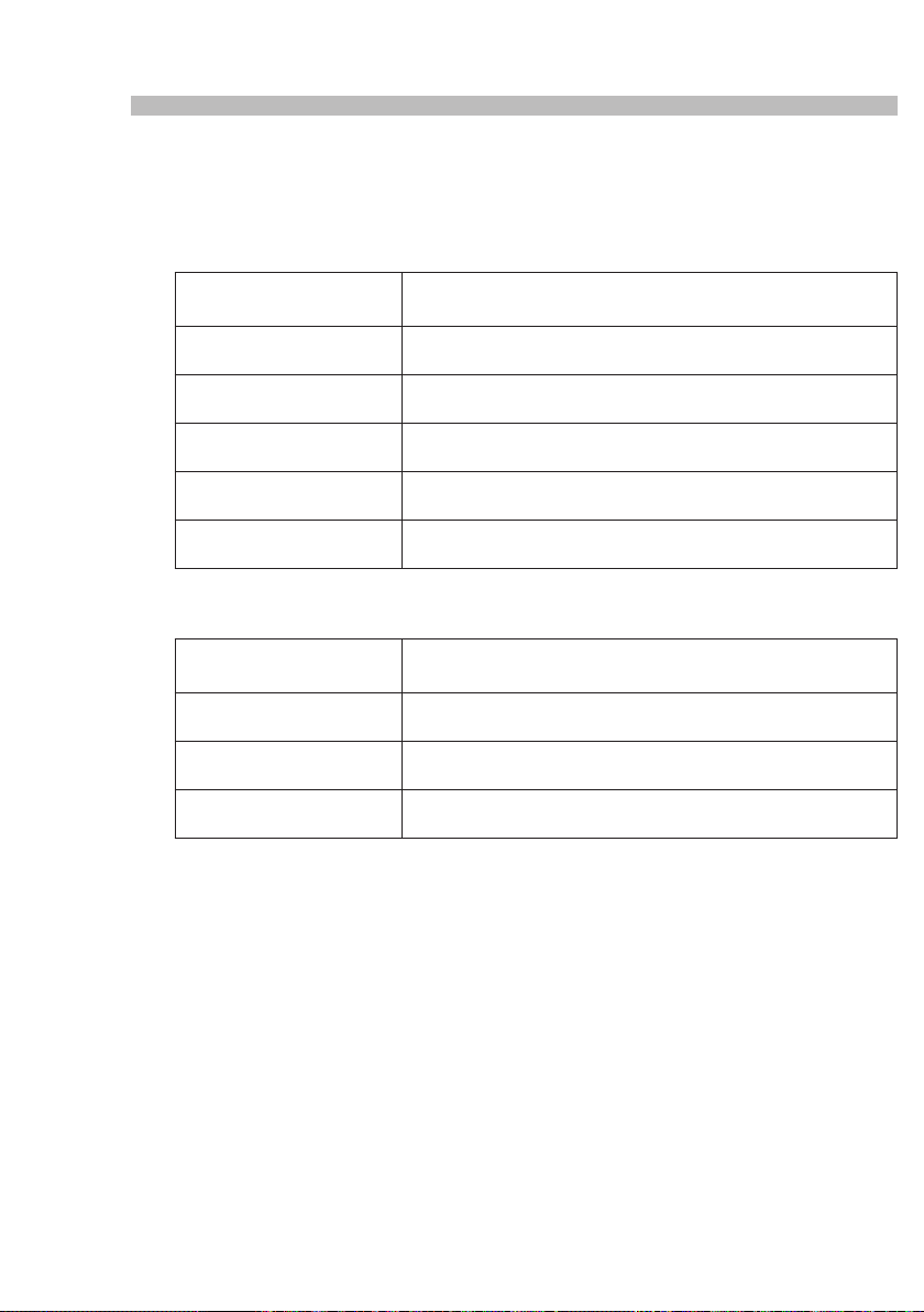
6.2 LED signalling
The LED indication of SECUREconnect 100 is an important means during start-up or when it
comes to trouble shooting. It provides information on the different statuses of the device.
6.2.1 LED indication on SECUREconnect 100R
LED green / LED red
0.5 Hz ashing alternately
LED green / LED red
1 Hz ashing alternately
LED green
0.5 Hz ashing
LED green
1 Hz ashing
LED red
2 Hz ashing
LED red
5 Hz ashing
Display with door open and closed.
6.2.2 LED indication on SECUREconnect 100F
LED green
1 Hz ashing
LED green
0.5 Hz ashing
LED green
off
LED green
5 Hz ashing
Display with door closed, and up to 15 s after door opening
Normal status, uncoded,
no communication with other devices linked to the GU-BKS-NET bus
Normal status, uncoded,
communication with at least one device linked to the GU-BKS-NET bus
Normal status, coded,
no communication with other devices linked to the GU-BKS-NET bus
Normal status, coded,
communication with at least one device linked to the GU-BKS-NET bus
Temperature too high
Trouble:
Short circuit
Normal status, uncoded,
Normal status, coded,
Power supply between SECUREconnect 100R and 100F interrupted
for a longer period of time
Trouble:
Short circuit, switch-off, capacitors....
Explanation:
5 Hz = 5 ashes per second
2 Hz = 2 ashes per second
1 Hz = LED 0.5 seconds on, 1 ash per second
0.5 Hz = LED 1 second on
44
Page 45
Power and Data Transmission Unit
6.3 Functions with motor-driven locks
(Direct connection to terminals V4, 91, 92, 93)
6.3.1 Short-time OPEN
If a potential-free contact connected to terminals 93 / V4 is actuated with the door closed, SECUREconnect 100F receives the signal to release the electrical lock and to retract the latch.
When the door is opened, the electrical lock will extend the latch again after 3 s, so the door will
be locked without delay as it is shut again.
If the door remains closed, the latchbolt will extend after 2 - 20 s (time adjustable).
Attention:
Here it may happen that the extended latchbolt hits the strike plate. In that
case, please check the locking status of the door.
If a potential-free contact (gating pulse) connected to terminals 93 / V4 is actuated permanently,
the electrical lock remains open for the duration of the signal.
• When the door is opened, the electrical lock will extend the latch again after 3 s.
• When the door is closed again, the electrical lock will retract the latch.
6.3.2 Permanent OPEN
If a potential-free contact connected to terminals 91 / V4 is actuated with the door closed,
SECUREconnect 100F receives the signal to retract the latch.
The latch remains retracted permanently.
Attention:
The electrical lock will not re-lock automatically.
The application of this function is not permitted with re rated doors
(DIN 18250) ! Non-compliance will result in the revocation of the door's
re approval !
6.3.3 Door locking
If a potential-free contact (gating pulse) connected to terminals 92 / V4 is actuated with the door
closed, SECUREconnect 100F receives the signal to re-lock the electrical lock.
Attention:
Here it may happen that the extended latchbolt hits the strike plate.
In that case, please check the locking status of the door.
45
Page 46
SECUREconnect 100
6.4 Function with electromechanical locks ('EK')
6.4.1 Short-time OPEN (engaging the lever handle)
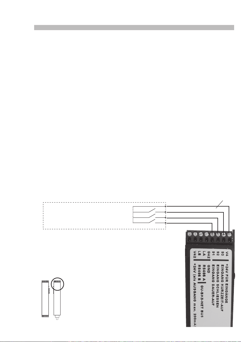
If a potential-free contact connected to terminals 93 / V4 is actuated with the door closed,
SECUREconnect 100F receives the signal to engage the lever handle.
• If the door remains closed, the lever handle will be disengaged again after 20 s.
• If the door is opened, the lever handle will be disengaged again after 3 s.
• If a potential-free contact connected to terminals 93 / V4 is actuated permanently, the
lever handle remains engaged remains for the duration of the signal (see above).
• If the door is opened, the lever handle will be disengaged again after 3 s.
• If the door is closed again, the lever handle will be re-engaged.
6.4.2 Permanent OPEN
If a potential-free contact (gating pulse) connected to terminals 91 / V4 is actuated with the
door closed, SECUREconnect 100F receives the signal to engage the lever handle.
• If the door remains closed, the lever handle will remain engaged.
• If the door is opened, the lever handle will be disengaged again after 3 s
•
If the door is closed again, the lever handle will be re-engaged.
6.4.3 Door closing (disengaging the lever handle)
If a potential-free contact connected to terminals 92 / V4 is actuated with the door closed,
SECUREconnect 100F receives the signal to disengage the lever handle.
Short-time OPEN (impulse), e.g. intercom
access control, timer switch
+ 24V short-time OPEN (impulse)
Close (impulse / handle disengaging)
Permanent OPEN (impulse)
46
Enclosed connection cable with
brown
white
yellow
green
terminals
Page 47

Power and Data Transmission Unit
6.5 Electrical function test
In order to verify if an assembly group has been connected properly, it is necessary to carry out
the following work steps:
1. Close door manually
2. Apply supply voltage to SECUREconnect 100R (e.g. 230V AC by means of a Europlug)
3. Bridge brown and white wire of connecting cable on SECUREconnect 100R
The lock function 'short-time OPEN' will be activated causing the electrical lock to unlock and
the outside lever handle to engage for a short moment, each.
47
Page 48
SECUREconnect 100
7 Connection diagrams
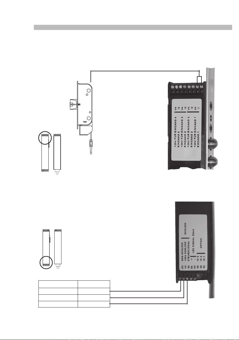
7.1 Latchbolt monitoring
System cable for
latchbolt monitoring
SECUREconnect 100F
7.2 Connection diagram Secury Automatik with A-opener
Impulse-controlled door opening time approx. 2 s (cannot be adjusted).
Permanent door opening time corresponds to duration of control signal
Connecting cable Signal
Grey (blue) GND (minus)
Brown 24V (plus)
Black Control line
48
SECUREconnect 100F
Page 49
Power and Data Transmission Unit
7.3 Switching the A-opener's acoustic signal on and off
1. Connect A-opener to SECUREconnect 100F according to connection diagram.
2. Disconnect SECUREconnect 100R from power supply.
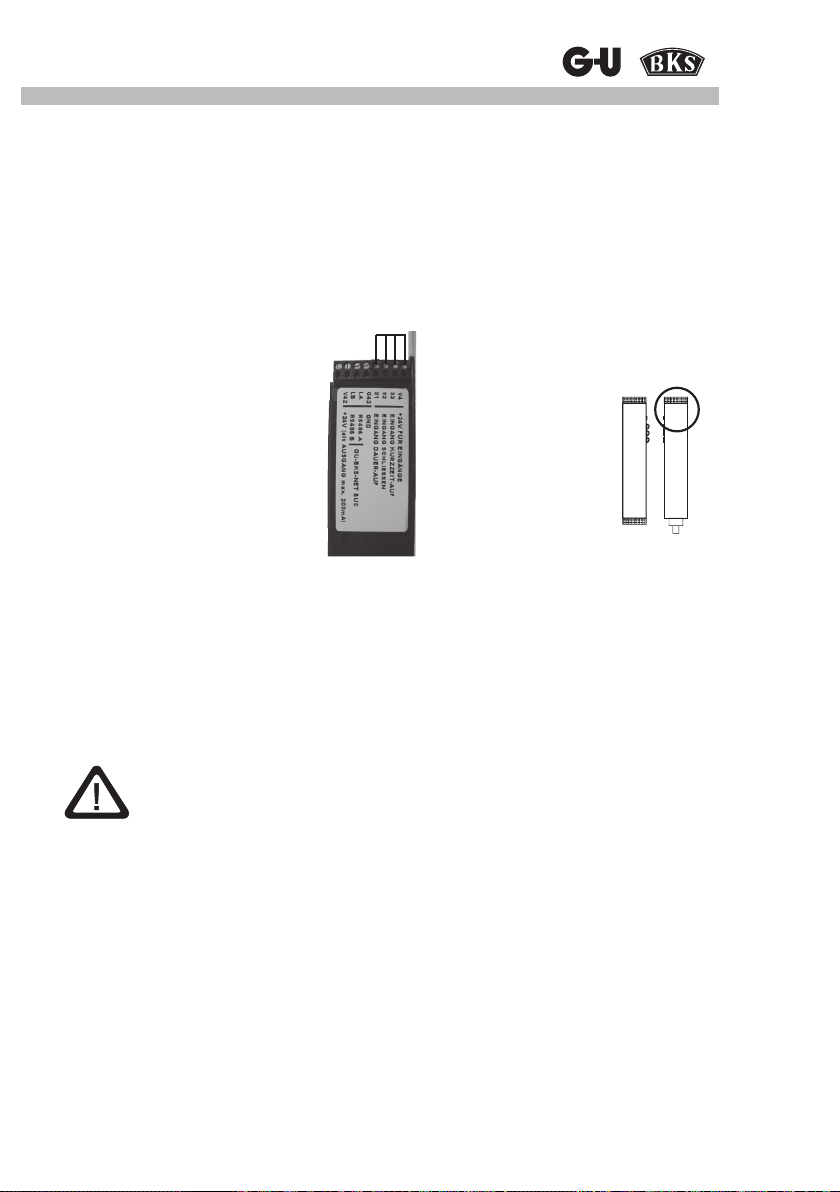
3. Bridge terminals V4, 93, 92, 91.
4. Wait until SECUREconnect 100F stops ashing.
5. Connect SECUREconnect 100R and 100F (e.g., by closing the door)
6. Switch-on voltage on SECUREconnect 100R.
An automatic switching sequence will be started and completed after 30 s. During this period
of time, the A-opener will not be active.
SECUREconnect 100R
Attention:
SECUREconnect 100R and 100F must not be separated during this period
(e.g. by opening the door)
7. Disconnect SECUREconnect 100R from power supply and remove bridges.
8. Wait until SECUREconnect 100F stops ashing.
9. Switch on power.
49
Page 50
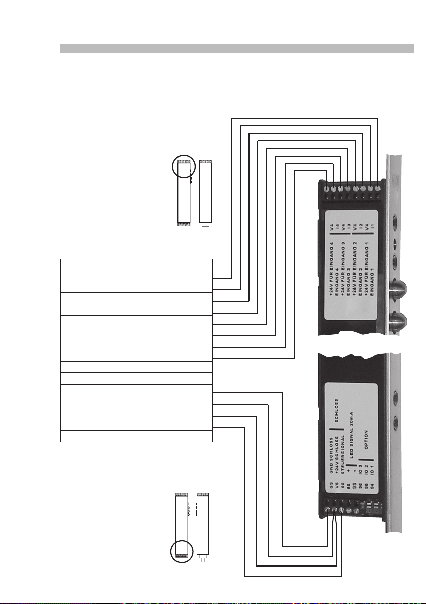
SECUREconnect 100
7.4 Connection diagram of motor-driven lock
Series 19 (with 14-wire connecting cable)
SECUREconnect 100F
Connecting
cable
Blue Locked COM
Red Locked NO
Black Unlocked COM
Purple Unlocked NO
Grey-pink Locking cam COM
Red-blue Locking cam NO
White-green Function output COM
Brown-green Function output NO
Green Not assigned
Yellow Function input
White GND
Brown + 24V
Grey Door contact
Pink Control line
Signal
50
Page 51
Power and Data Transmission Unit
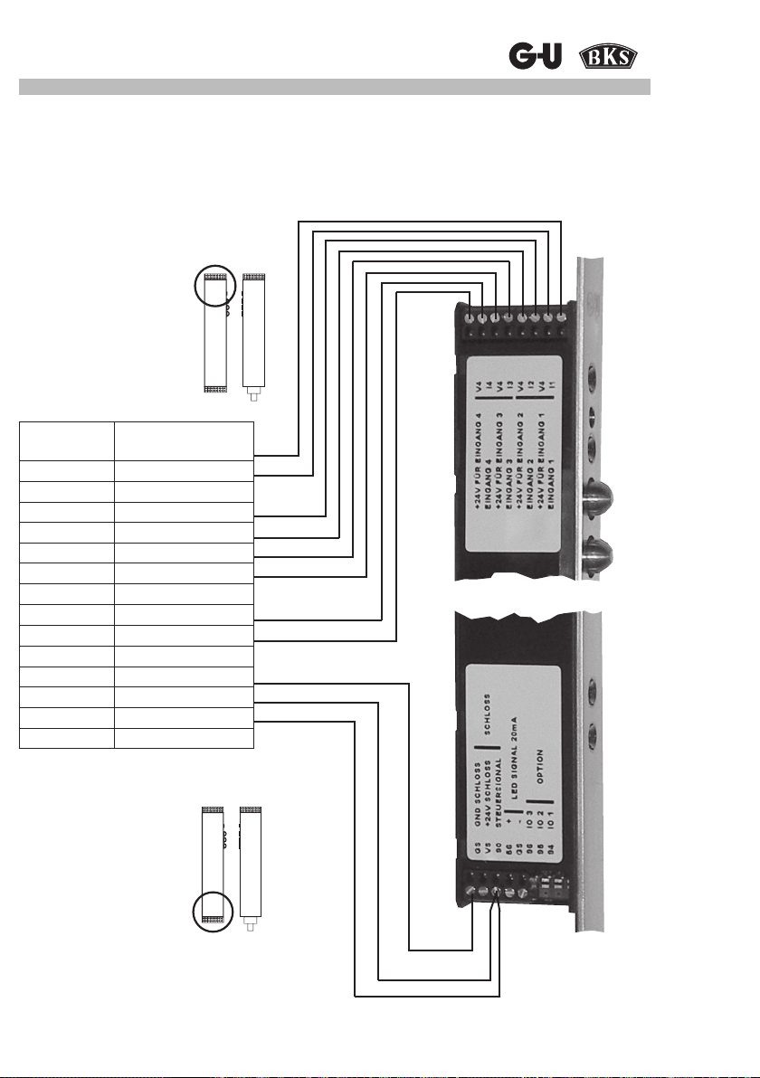
7.5 Connection diagram of ‘EK‘ lock
Series 19 (with 14-wire connecting cable)
SECUREconnect 100F
Connecting
cable
Blue Locked COM
Green Locked NO
Grey Locked NC
Red Cyl. locking cam COM
Yellow Cyl. locking cam NO
Purple Handle side 1 COM
Red-blue Handle side 1 NO
Brown-green Handle side 1 NC
White-green Handle side 2 COM
Grey-pink Handle side 2 NO
Black Handle side 2 NC
White GND
Brown +12 - 24V
Pink Control line
Signal
51
Page 52
SECUREconnect 100
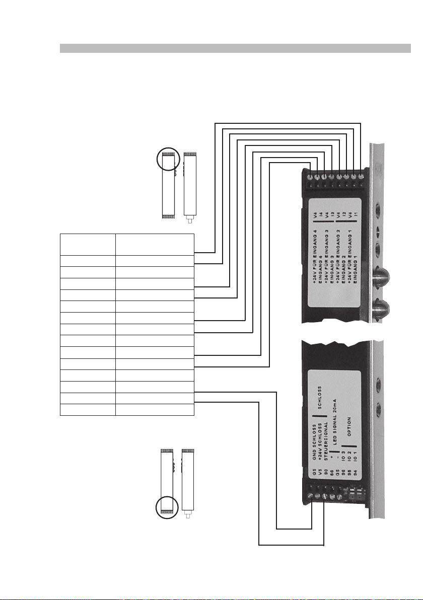
7.6 Connection diagram of ‘EK‘ lock
Series 21 (with 14-wire connecting cable)
SECUREconnect 100F
Connecting
cable
Blue Locked COM
Green Locked NO
Grey LockedNC
Red Cyl. locking cam COM
Yellow Locking cam NO
Pink Schließbart NC
Purple Handle side 1 COM
Red-blue Handle side 1 NO
Brown-green Handle side 1 NC
White-green Handle side 2 COM
Grey-pink Handle side 2 NO
Black Handle side 2 NC
White GND
Brown +12 - 24V
Signal
52
Page 53
Power and Data Transmission Unit
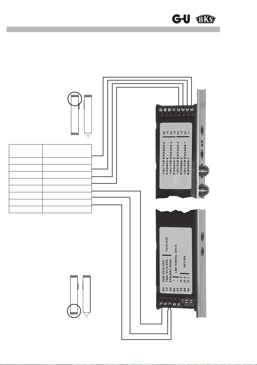
7.7 Connection diagram of ‘EK‘ lock
Series 21 (with 8-wire connecting cable)
SECUREconnect 100F
Connecting
cable
Blue Locked COM
Grey Locked NO
Green Locked NC
Red Cyl. locking cam COM
Yellow Cyl. locking cam NO
White GND
Brown +12 - 24V
Pink Control line
Signal
53
Page 54
SECUREconnect 100
7.8 Control via IO10 modules
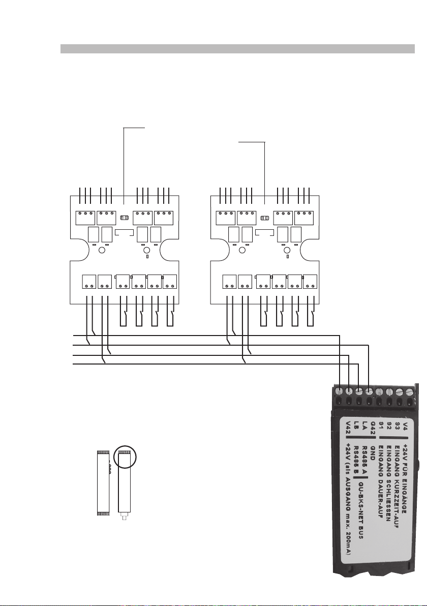
Please bear in mind that each module has a different address setting.
Address jumper
Closed: Device 1
Open: Device 2
COM
NCNCCOM
NO
NC
COM
NO
NC
COM
NO
NC
COM
NO
NO
NC
COM
NO
NC
COM
NO
NC
COM
NO
61 41 51 61 41 5162 42 52 62 42 5263 43 53 63 43 5364 44 54 64 44 54
Address
Service Service
IO10-1
G1 V1 LA LB G1 V1 LA LBV9 I1 V9 I1V9 I2 V9 I2V9 I3 V9 I3V9 I4 V9 I4
Address
IO10-2
54
Page 55
Power and Data Transmission Unit
7.8.1 IO10 module inputs
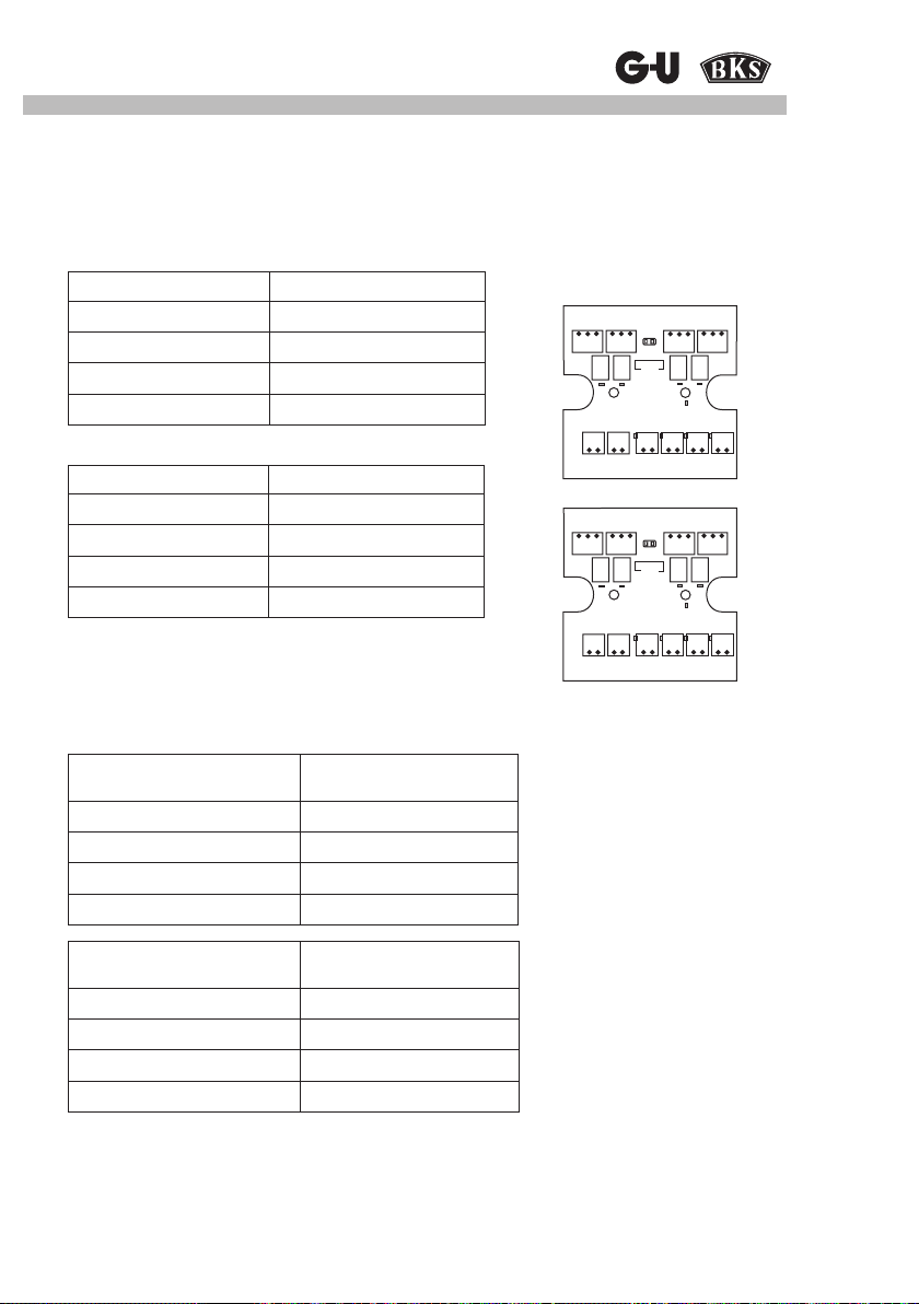
Two IO10 modules can be connected to SECUREconnect 100R via terminals LA and LB.
Input and output parameters are preset in compliance with the GU-BKS-NET concept.
Basic settings of IO10 address 1:
Input Function
Input 1: terminal I1, V9 Permanent OPEN
Input 2: terminal I2, V9 Close
Input 3: terminal I3, V9 Priority locking
Input 4: terminal I4, V9 Priority unlocking
61 41 51 62 42 52 6343 53 64 44 54
Service
Basic settings of IO10 address 2:
G1 V1 LALB V9 I1 V9 I2 V9 I3 V9 I4
Input Function
Input 1: terminal I1, V9 Non-priority unlocking
Input 2: terminal I2, V9 -
Input 3: terminal I3, V9 Short-time OPEN
61 41 51 62 42 52 6343 53 64 44 54
Service
Input 4: terminal I4, V9 -
7.8.2 IO10 module outputs
G1 V1 LALB V9 I1 V9 I2 V9 I3 V9 I4
The input statuses (SECUREconnect 100F) are put out directly to the IO10 module relays.
Basic settings
Input
(SECUREconnect 100F)
Input 1: terminal I1, V4 Relay 1: terminal 41, 51, 61
Input 2: terminal I2, V4 Relay 2: terminal 42, 52, 62
Input 3: terminal I3, V4 Relay 3: terminal 43, 53, 63
Input 4: terminal I4, V4 Relay 4: terminal 44, 54, 64
Input
(SECUREconnect 100F)
Input 1: terminal I1, V4 Relay 1: terminal 41, 51, 61
Input 2: terminal I2, V4 Relay 2: terminal 42, 52, 62
Input 3: terminal I3, V4 Relay 3: terminal 43, 53, 63
Input 4: terminal I4, V4 Relay 4: terminal 44, 54, 64
Output
IO10 address 1
Output
IO10 address 2
55
Page 56

SECUREconnect 100
8 Inspection and maintenance works, replacement parts
SECUREconnect 100 may only be operated with the original mains adaptor or with 230V AC.
If other than original products are used, all product liability, warranty, and service claims will
expire.
If replacement parts or extensions are required, orignial parts may be used exclusively.
Maintenance and repair works must only be carried out by experts trained and authorised by
the manufacturer.
Locks:
The serviceability of the locking system must be veried at regular intervals. For doing so,
check all all xing points and retighten screws, if required. In order to avoid that the mechani-
cal properties of the lock – especially with regard to key, handle, and latchbolt movement – are
affected by dirt, it is necessary that the lock is inspected and lubricated (e.g. with BKS maintenance spray) at regular intervals.
SECUREconnect 100
SECUREconnect 100 is maintenance-free.
We recommend that the contacts be cleaned with a soft and dry cloth occasionally.
By no means use cleaning agents and lubricants containing oil or silicone.
9 Disposal
The device contains electronic parts and must be disposed of in compliance with the legal
regulations.
56
Page 57

Power and Data Transmission Unit
Notes:
57
Page 58

SECUREconnect 100
Notes:
58
Page 59

Power and Data Transmission Unit
Notes:
59
Page 60

Gretsch-Unitas GmbH
Baubeschläge
Johann-Maus-Str. 3
71254 Ditzingen
www.g-u.com
0-45654-L0-0 - Mod. 2 - Alle Rechte, Irrtümer und Änderungen vorbehalten. / All rights reserved. Errors excepted. Subject to change without notice.
 Loading...