

Page 1
Page 2

SpectroEye™6
Page 3

Welcome!
SpectroEye is a spectrophotometer which, just as all new
GretagMacbeth products, has a fully modular structure, and so is
extremely flexible and easy to use. The purpose of this manual is
to illustrate the various fields of application and how to integrate
SpectroEye into your working environment in the most effective way
possible.
We hope you enjoy reading the manual, and enjoy working with
your SpectroEye as well.
We welcome any suggestions or ideas you may have for
improvements. Contact us through your authorised dealer,
or via the Internet!
The GretagMacbeth SpectroEye development team.
Set-up
Use
1
2
SpectroEye™ 3
Functions
Appendix
3
4
Page 4
Specific safety recommendations
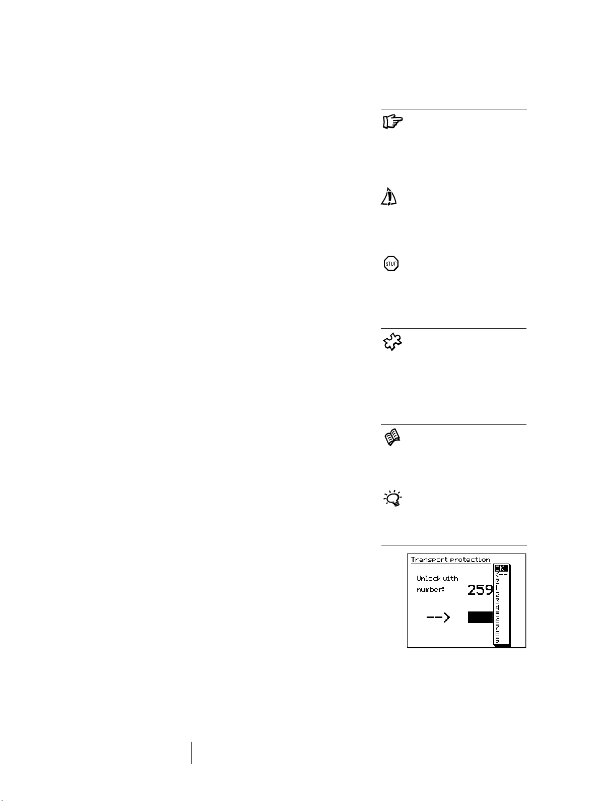
This section contains particularly
important information for the correct
use of the instrument and for
achieving good results. Failure
to observe these warnings could
result in errors or loss of data!
Failure to observe the following
recommendation could result in
damage to the SpectroEye or
other equipment, for which
GretagMacbeth declines all
responsibility.
Failure to observe the following
recommendations could
compromise personal safety
and that of others.
Brief guide to the manual
The manual is divided into four chapters: Set-up, Use, Practice and
Appendix. The content of each chapter is given to the right. This system
gives quick and precise access to the information you require.
The page layout of the manual includes two columns. The wider
text column contains all the functional descriptions, examples and
explanations. These are clarified, integrated or indicated by additional
information, such as “Screenshots” and recommendations, highlighted
in grey in the outer column. We recommend getting to know these
supplements and their relative symbols by carefully reading the
corresponding explanations in the left margin.
Additional function symbol
The function described here is
not part of the SpectroEye basic
specifications. The corresponding
description should only be read if
the related function package
is installed on your instrument.
Other recommendations
If additional information on the
subject illustrated is contained
in other sections of the manual,
the “book” symbol refers to the
corresponding chapter.
Brief recommendations for putting
theoretical information into practice.
Screenshots
SpectroEye™4
Brief guide to the manual
Page 5
As well as important safety recommendations, this chapter
contains all the information necessary for setting-up and
using the measuring device.
This chapter is an introduction to the operating principles
of the device. It illustrates how to make chromatic
measurements and comparisons with the SpectroEye
through a number of classic application examples.
Set-up
Use
1
2
In this chapter we will take a detailed look at
selected functions which highlight the high standard
of the SpectroEye unit.
The appendix contains information regarding machine
messages, technical specifications, mathematical formulas,
bibliographic references and the quick reference index.
Functions
Appendix
3
4
SpectroEye™ 5
Structure of the manual
Page 6

SpectroEye™6
Page 7

1.1 General
1.1.1 General safety recommendations 9
1.1.2 Supply specifications 10
1.1.2.1 Basic equipment and accessories 10
1.1.2.2 Equipment firmware 11
1.1.3 SpectroEye functional elements 12
1.2 SpectroEye preparation
1.2.1 Charging the batteries 13
1.2.2 Transportation safety deactivation 13
1.2.3 SpectroEye connection options 14
1.2.3.1 Communications adapter 14
1.2.3.2 Connecting the battery charger 15
1.2.3.3 Connecting to a PC 15
1.2.3.4 Connecting to a Macintosh 16
1.2.3.5 Connecting to a printer 16
1.2.3.6 Connecting to a Seiko printer 17
1.2.3.7 Connecting to the Ethernet 18
Set-up
Use
1
2
1.3 Transport 18
Functions
Appendix
3
4
SpectroEye™ 7
1 • Set-up
Page 8

SpectroEye™8
Kapitel
Page 9
1 Set-up
1.1 General
1.1.1 General safety recommendations
Failure to observe the safety recommendations and instructions
given by this manual may result in measurement error and loss
of data, as well as damage to persons and property.
SpectroEye is not flameproof, therefore the device must
not be used in environments where the risk of explosion
exists, or in areas subject to strong electromagnetic fields.
Do not use SpectroEye in ambient temperatures
in excess of 40°C (104° F).
Never open SpectroEye. Unauthorised opening of
the device shall immediately invalidate the warrantee.
For any repairs, contact your authorised dealer.
Ensure that the supply cable provided is connected
to a mains socket equipped with earth contact to avoid
a shock hazard.
To avoid operating errors, SpectroEye should be used
exclusively by specifically trained personnel.
SpectroEye must only be used on dry, flat, horizontal
and stable surfaces, and must not be exposed to direct
sunlight.
SpectroEye must only be used in the operating
conditions specified below.
SpectroEye must be protected from chemical
substances, corrosive vapours, strong mechanical
vibration and impact.
Use only GretagMacbeth original spare parts
and accessories.
For transport purposes only use the original packing
and secure the instrument with the transport protection
(Settings > General > Transport protection).
1
The specified operating conditions
are given in the appendix under
item 4.1 “Technical specifications”.
Read chapter 1.3.
The SpectroEye case must be kept clean using
a clean cloth slightly dampened in soapy water.
SpectroEye™ 9
1 • Set-up
Page 10
1
1.1.2 Supply specifications
1.1.2.1 Basic equipment and accessories
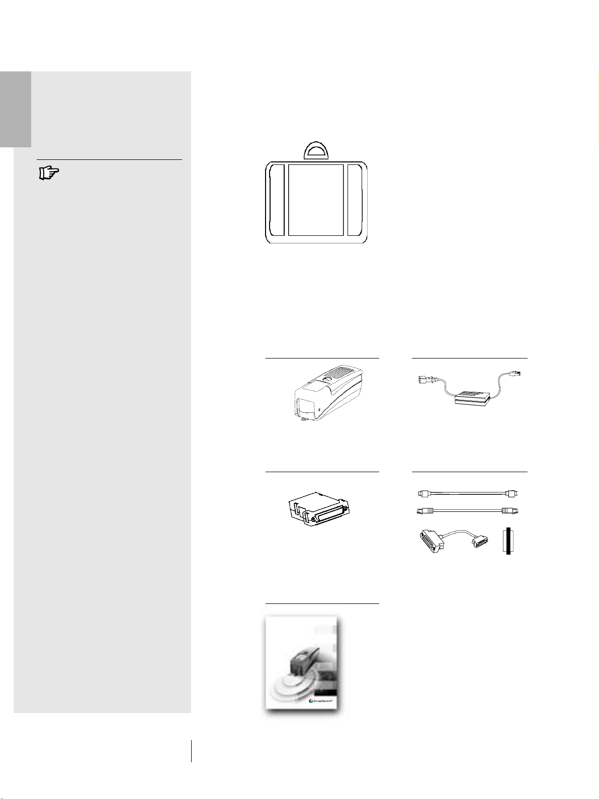
The SpectroEye and related standard accessories are delivered
in a case.
It is advisable to keep the case in
good condition ! If the SpectroEye
has to be transported or shipped,
it must be packed in the original
case to avoid damage.
GretagMacbeth declines all
responsibility for damage to the
SpectroEye during transport
caused by inadequate packaging.
On delivery, check that the content of the case is complete.
The following elements must be present:
1. SpectroEye
2. Battery charger
3. Communications adapter 4. Connecting cable set
5. Operating manual
Operating manual
™
SpectroEye
SpectroEye™10
1 • Set-up
Page 11
1.1.2.2 Equipment firmware
The firmware for the SpectroEye has a modular configuration.
This means that the range of functions must be configured
according to requirements when the device is purchased,
and that possible supplementary functions can be added
at any time.
• The basic instrument is equipped with the following
standard measurement functions:
Densitometry - Density
Spectrum - Reflection spectrum
Colorimetry - CIELAB with CIE L*a*b*,
CIE L*C*h (a*b*) and E CIELAB
• The following additional functions may be purchased
and enabled:
Densitometry - All densities
- Dot gain
- Dot area
- Contrast
- Trapping
- Hue error
- Greyness
- Print characteristic
- Printing plate
- Auto function
Spectrum - Density spectrum
Colorimetry - CIE XYZ, CIE xyY
- CIELUV with CIE L*u*v*,
CIE L*C*h (u*v*) and E CIELUV
- LABmg, LCHmg and Emg
- Hunter Lab and E Hunter Lab
- Reflection factor RxRyRz
Color difference - Metamerism, E*94, E CMC,
E FMCII
Dye strength - Absolute (K/S) and relative (DS)
White- and Yellowness - W CIE, W E313, W Berger,
W Stensby, ISO Brightness R457,
Y E313, Y D1925, T CIE
Special functions - Best Match
Color guides - Pantone
®
Color Formula Guide,
HKS E/K/N/Z, TOYO Color Finder,
DIC Color Guide
Security - Setting protection
- Multiple users
1
Indications regarding basic and
supplementary functions are as
per Nov. '98. Modifications may
be made at any time.
Contact your GretagMacbeth dealer
who will be happy to inform you
of any innovations or variations.
When reading this manual, check
if the description of these
supplementary functions is
indicated by the puzzle symbol.
This will save you the time of reading
sections regarding functions which
are not applicable to your instrument.
SpectroEye™ 11
1 • Set-up
Page 12
1
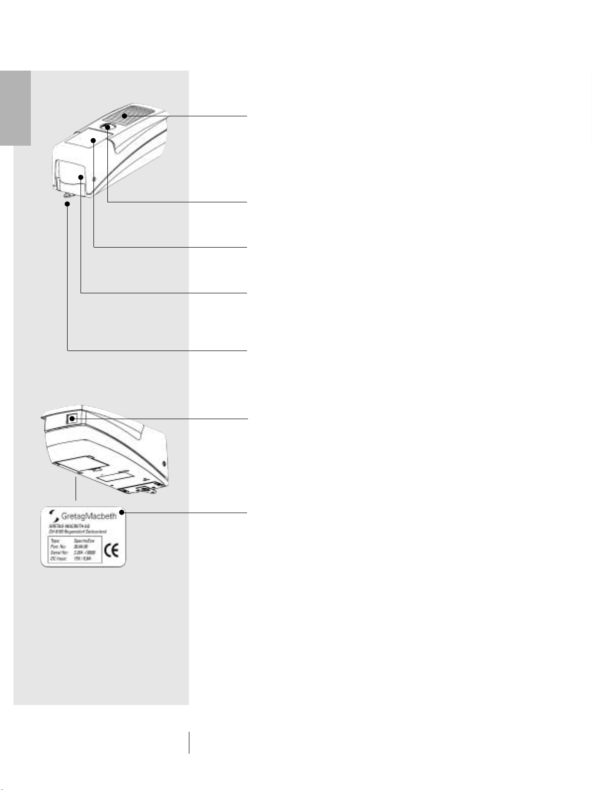
1.1.3 SpectroEye functional elements
Measurement pad
Pressing lightly on this pad starts a measurement or selects
the menu option highlighted on the display.
Control wheel
Instrument firmware functions, menu options or measurement
windows can be selected using this wheel.
The display
The display is easy to view and has graphic capabilities.
It displays the available functions and measurement results.
Measurement module
The moving measurement head contains the optics, the built-in
white reference and automatic filter wheel, in a high precision
multiple use measurement module.
Targeting aperture
The targeting aperture is fully visible. Quick and accurate
positioning is simple even with small color patches
and color bars.
Data port
The SpectroEye is equipped with a multi-function port.
Data exchange, protocol management and battery charging
are all performed by the same interface.
Serial plate
The certification plate gives the main specifications of the
SpectroEye at a glance. The serial number of the instrument
is very important, and must be quoted when contacting
GretagMacbeth either by phone or via the Internet.
SpectroEye™12
1 • Set-up
Page 13
1.2 SpectroEye preparation
1.2.1 Charging the batteries
The SpectroEye is subject to quality control and the batteries
are charged prior to delivery. If a long period of time passes
between delivery from GretagMacbeth and Set-up, the
instrument must be recharged using the battery charger
supplied.
1
Procedure
1. Connect the battery charger to the mains supply by means
of the mains cable
2. Insert the charging plug into the SpectroEye port
3. Recharge the instrument for approximately three hours
4. Remove the charging cable and disconnect the battery
charger from the mains when charging is complete
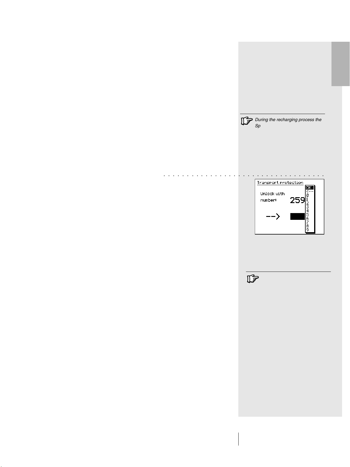
1.2.2 Transportation safety deactivation
The SpectroEye is fitted with an electronic transportation
safety system, which prevents involuntary operation and
thus damage to the measuring head due to impact or vibration
during transport.
Procedure
1. Press the measurement pad area down for about three
seconds to cancel any input which may have been created
by transport and unpacking movements.
2. Briefly press the measurement pad. The display shows
the field for entering code 259 and a window for the number
selection.
3. At this point enter the numbers 2, 5 and 9 in succession,
pressing the measurement pad each time to choose a
number. If a mistake is made during code entry or you wish
to cancel a single entry, bring the cursor bar to
the measurement pad. To cancel the entire sequence, keep
the measuring pad pressed for about three seconds.
4. If the figures have been correctly entered, bring the cursor
bar to the OK field and press the measurement pad.
The display will then show a menu.
5. Bring the cursor bar to the item Return on the displayed
menu and press the measurement pad until the main menu
appears.
During the recharging process the
SpectroEye tends to becom warm.
This is due to the rapid charge
system and is perfectly normal.
○○○○○○○○○○○○○○○○○○○○○○○○○○○○○○○○○○○
For transportation always secure
the instrument with the transport
protection (read chapter 1.3).
<- and press
SpectroEye™ 13
1 • Set-up
Page 14
1
If the SpectroEye does not require
connection to any other instrument,
the battery charger can also be
connected directly.
1.2.3 SpectroEye connection options
The SpectroEye connection socket is multi-functional, meaning
that the power supply, serial communications and the Ethernet
are built into one socket. It is possible to connect single devices
directly to the SpectroEye, or various devices simultaneously
by means of the communications adapter.
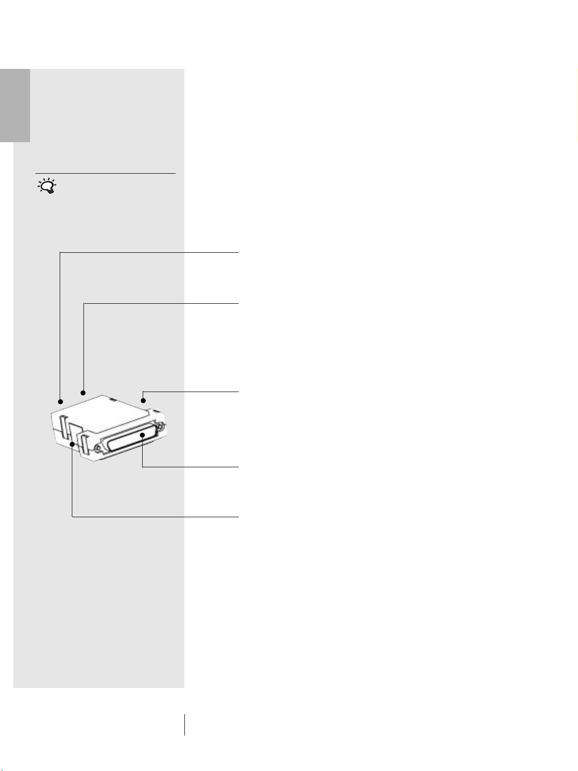
1.2.3.1 Communications adapter
This adapter connects the SpectroEye to all the possible
accessories: computer (PC or Macintosh), network, printer
or battery charger. Various connections can be made
simultaneously through the adapter, with only one cable
connected to the instrument itself.
GretagMacbeth Instrument
The SpectroEye is connected to the connector cable through
this socket.
Ethernet = / Power
Ethernet or the battery charger can be connected to this socket.
This Ethernet connection is not crossed and can be used when
the SpectroEye is connected to the network via a Hub. If the
socket is not used for Ethernet, the battery charger can be
connected here.
Ethernet X / Power
Ethernet or the battery charger can be connected to this socket.
This Ethernet connection is crossed, and is used when the
SpectroEye is connected directly to a PC. If the socket is not
used for Ethernet, the battery charger can be connected here.
Serial 1
This socket is used for serial communications if a Mini DIN
shaped plug is not available.
Serial 2
This socket is used for serial communications if a Mini DIN
shaped plug is available.
SpectroEye™14
1 • Set-up
Page 15
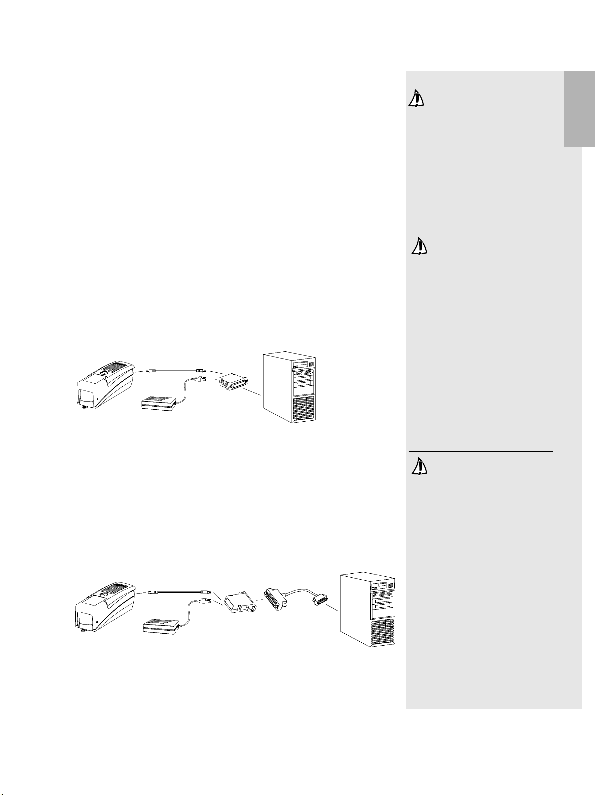
1.2.3.2 Connecting the battery charger
1. Insert connecting cable 36.64.31 into the SpectroEye
data port.
2. Insert the other end of the connecting cable into the
GretagMacbeth instrument socket of the communications
adapter.
3. Insert the battery charger plug into a free Power socket
on the communications adapter. The battery charger is
connected to the mains electricity supply by means of
the power cord supplied.
1.2.3.3 Connecting to a PC
Connecting to a PC with 25 pin serial interface port
1. Insert connecting cable 36.64.31 into the SpectroEye
data port.
2. Insert the other end of the connecting cable into the
GretagMacbeth instrument socket of the communications
adapter.
3. Connect the Serial socket on the communications adapter
to the PC port.
36.64.31
Take care to use the right
connecting cable!
1
Take care to use the right
connecting cable!
36.64.64
36.64.95
Connecting to a PC with 9 pin serial interface port
1. Insert connecting cable 36.64.31 into the SpectroEye
data port.
2. Insert the other end of the connecting cable into the
GretagMacbeth instrument socket of the communications
adapter.
3. Insert the intermediate cable 36.50.55 between the Serial
socket on the communications adapter and the PC port.
36.64.31
36.64.64
36.64.95
36.50.55
Take care to use the right
connecting cable!
SpectroEye™ 15
1 • Set-up
Page 16
1
Take care to use the right
connecting cable!
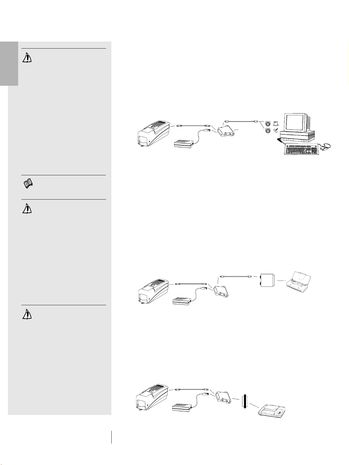
1.2.3.4 Connecting to a Macintosh
1. Insert connecting cable 36.64.31 into the SpectroEye
data port.
2. Insert the other end of the connecting cable into the
GretagMacbeth instrument socket of the communications
adapter.
3. Insert the intermediate cable 36.50.54 between the Serial
socket on the communications adapter and the Macintosh
port.
36.64.31
36.64.95
36.50.54
36.64.64
For connecting to the specific Seiko
model DPU 411 or DPU 414 printer,
read section 1.2.3.6.
Take care to use the right
connecting cable!
Take care to use the right
connecting cable!
1.2.3.5 Connecting to a printer
Connecting a printer through a parallel interface
1. Insert connecting cable 36.64.31 into the SpectroEye
data port.
2. Insert the other end of the connecting cable into the
GretagMacbeth instrument socket of the communications
adapter.
3. Insert converter 36.50.92 into the printer interface port.
4. Connect the converter with the proper battery charger.
5. Insert the intermediate cable 36.50.54 between the
communications adapter Serial port and the converter.
36.50.54
36.64.31
36.50.92
36.64.64
36.64.95
Connecting to a printer with serial interface
1. Insert connecting cable 36.64.31 into the SpectroEye
data port.
2. Insert the other end of the connecting cable into the
GretagMacbeth instrument socket of the communications
adapter.
3. Insert adapter 11.50.70 between the communications
adapter Serial port and the printer.
36.64.31
11.50.70
SpectroEye™16
1 • Set-up
36.64.64
36.64.95
Page 17
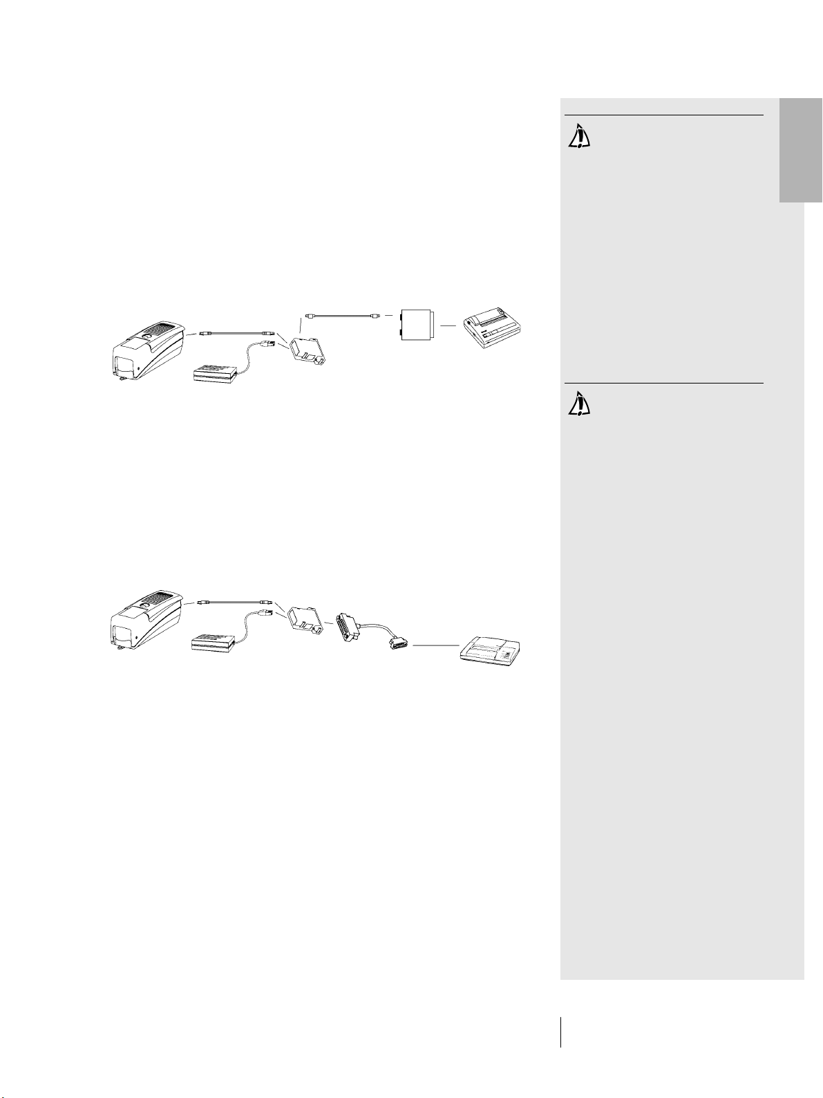
1.2.3.6 Connecting to a Seiko printer
Connecting to a Seiko model DPU 411 printer
1. Insert connecting cable 36.64.31 into the SpectroEye
data port.
2. Insert the other end of the connecting cable into the
GretagMacbeth instrument socket of the communications
adapter.
3. Insert Seiko adapter 36.51.37 into the printer interface port.
4. Insert the intermediate cable 36.50.54 between the communications adapter Serial port and the printer interface port.
36.50.54
36.64.31
36.51.37
36.64.64
36.64.95
Connecting to a Seiko model DPU 414 printer
1. Insert connecting cable 36.64.31 into the SpectroEye
data port.
2. Insert the other end of the connecting cable into the
GretagMacbeth instrument socket of the communications
adapter.
3. Insert the intermediate cable 36.65.04 between the communications adapter Serial port and the printer interface port.
36.64.31
36.65.04
Take care to use the right
connecting cable!
1
Take care to use the right
connecting cable!
36.64.95
36.64.64
SpectroEye™ 17
1 • Set-up
Page 18
1
Take care to use the right
connecting cable!
1.2.3.7 Connecting to the Ethernet
Connection to the Ethernet via hub
1. Insert connecting cable 36.64.31 into the SpectroEye
data port.
2. Insert the other end of the connecting cable into the
GretagMacbeth instrument socket of the communications
adapter.
3. Insert the Ethernet cable into the Ethernet = socket on
the communications adapter.
Take care to use the right
connecting cable!
GretagMacbeth declines all
responsibility for damage to the
SpectroEye during transport caused
by inadequate packaging and
protection.
Connection to the Ethernet directly on computer
1. Insert connecting cable 36.64.31 into the SpectroEye
data port.
2. Insert the other end of the connecting cable into the
GretagMacbeth instrument socket of the communications
adapter.
3. Insert the Ethernet cable into the Ethernet X socket on
the communications adapter.
1.3 Transport
For transporting the SpectroEye, always use the original case
and secure the instrument with the transport protection.
To activate the transport protection, select the following from
main menu:
Settings > General > Transport protection > Lock transport
protection
and confirm with Yes.
To remove the transport protection, simply enter the
number 259.
SpectroEye™18
1 • Set-up
Page 19

2.1 Instrument philosophy and
firmware structure
2.1.1 Color measurement and comparison 21
2.1.2 Data management 22
2.1.3 User selection 22
2.2 Operating principles
2.2.1 Menu 23
2.2.2 Measurement window 25
2.2.2.1 Measurement window structure 25
2.2.2.2 The symbols bar 26
2.3 Initial settings
2.3.1 General settings 29
2.3.1.1 Data interface 30
2.3.1.2 LCD contrast 31
2.3.1.3 Date and time 31
2.3.2 User defined settings 32
2.3.2.1 Turn display 32
2.3.2.2 Printer 33
2.3.2.3 Measurement set-up 34
Set-up
Use
1
2
2.4 Working with the SpectoEye
2.4.1 Single measurement 39
2.4.1.1 Checking the measurement conditions 39
2.4.1.2 Reference and sample measurement 40
2.4.1.3 Comparison of measurement values 40
2.4.1.4 Graphical representation of measurement 41
results
2.4.1.5 Printing the measurement values 42
2.4.1.6 Switching between measurement functions 43
2.4.2 Series measurement 44
2.4.2.1 Creating a series of references 44
2.4.2.2 Additional processing and deleting
of references 45
2.4.2.3 Measurement of samples 45
2.4.2.4 Assigning samples to a reference 46
2.4.2.5 Repeating a series 46
2.4.3 Jobs 47
2.4.3.1 Creating a job 47
2.4.3.2 Measurement of samples 49
2.4.3.3 Additional processing and deleting 50
of samples
2.4.3.4 Remeasure a job 50
Functions
Appendix
3
4
SpectroEye™ 19
2 • Use
Page 20

2
2.5 Database management and maintenance
2.5.1 Jobs 51
2.5.1.1 Modification of jobs data 51
2.5.1.2 Delete jobs 52
2.5.2 Reference libraries 53
2.5.2.1 Creating a new library 53
2.5.2.2 Managing an existing library 54
2.5.2.3 Deleting a reference library 54
2.5.3 Users 55
2.5.3.1 Creating new users 55
2.5.3.2 Modifiy user 56
2.5.3.3 Delete user 56
2.6 Settings
2.6.1 General settings 57
2.6.1.1 Date interface 57
2.6.1.2 Setting protection 58
2.6.1.3 LCD contrast 59
2.6.1.4 Date and time 59
2.6.1.5 Battery 60
2.6.1.6 New functions 60
2.6.1.7 Instrument type 61
2.6.1.8 Service 61
2.6.1.9 Transport protection 61
2.6.2 User defined settings 62
2.6.2.1 Measurement set-up 62
2.6.2.2 Functions access 68
2.6.2.3 Printer 69
2.6.2.4 Turn display 70
2.6.2.5 Language 70
SpectroEye™20
2 • Use
Page 21
2. Use
The SpectroEye has just two control devices to control the
instrument operations, the control wheel and the measurement
pad. The measurement pad is designed according to technicalapplication criteria so the functions can be adapted to individual
user requirements quickly and easily.
Based on concrete examples, this chapter illustrates both the
principles of the instrument and its use.
2.1 Instrument philosophy and firmware
structure
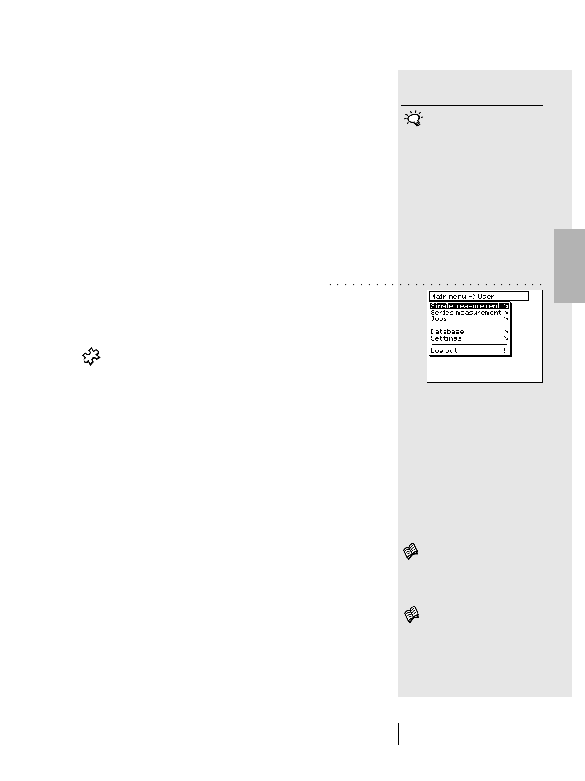
The starting point for instrument use is the Main Menu
(see figure). The Main Menu is subdivided into three activity
sectors as follows:
1. Colour measurement and comparison
2. Data management
3. User selection
A detailed illustration of these three sectors is given in the
following sections.
This chapter must be read carefully.
It contains important basic information which is helpful for a quick
understanding of the SpectroEye
operation and how to obtain
the best possible performance.
○○○○○○○○○○○○○○○○○○○○○○○○○○○○
2
2.1.1 Color measurement and comparison
There are three ways in which sample measurement and
comparison can be accomplished. Which is chosen will depend
on the operating mode the operator wishes to use and the
measurement application.
The choices are:
• Single measurement
• Series measurement
• Jobs
In Single measurement you can measure a single sample, or
you can compare a single sample with a reference, without
saving the results into the instrument. Each new measurement
overwrites the preceding value.
In Series measurement you have the option of saving various
references into the instrument as Series. The measured sample
is assigned to the corresponding reference either automatically
or manually. While the reference values are kept stored until
deleted by the operator, the samples are overwritten for each
new measurement.
Read chapter 2.4.1
Read chapter 2.4.2
SpectroEye™ 21
2 • Use
Page 22
2
Read chapter 2.4.3
2.1.2 Data management
○○○○○○○○○○○○○○○○○○○○○○○○○
Using Jobs you can create complete jobs with all the relevant
information. As well as the name of the job, conditions of
measurement, etc. all the references and all the samples are
saved by the instrument. The assignment of measured samples
to their corresponding references may be either automatic or
manual. All data remain saved until they are deleted by the
operator.
Data stored in the instrument for long periods must be managed
and maintained. It is also possible to establish and modify the
fundamental settings.
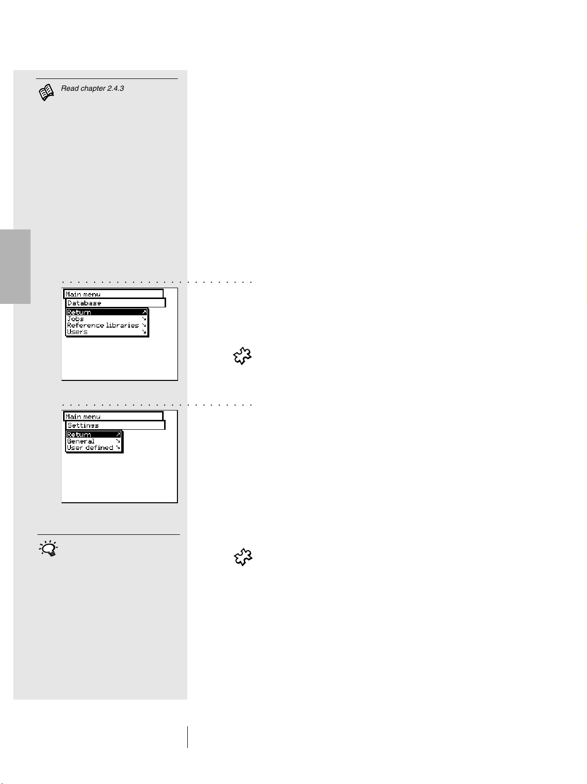
At the Data management level, there is a distinction between:
• Database
• Settings
The following is managed in the Database:
- Jobs Client data, measurement conditions
- Reference libraries Collection of references which are
automatically created, apart from
the color guides.
- Users Creation and modification of the various
users and related passwords
○○○○○○○○○○○○○○○○○○○○○○○○○
2.1.3 User selection
With the Multiple User option the
instrument is configured so that
each user works with the functions
and setting set for their own
particular type of work. This further
serves to protect data and settings
from possible unauthorised access.
In Settings, there are general settings and user defined settings:
- General Specific instrument settings, shared
by users, such as LCD contrast, date
and time, etc.
- User defined Specific user settings, such as the
setting of the LCD for right-handed
or left-handed use, measurement
conditions, etc.
If the Multiple Users package has been purchased and installed,
the Log out option is given as the last item on the main menu.
This serves to protect specific user data from possible
unauthorised access. It puts the SpectroEye into a protected
condition, and the instrument can only be rendered operative
by entering a user name and password.
SpectroEye™22
2 • Use
Page 23
2.2 Operating principles
Through the main menu, the software of the SpectroEye leads
to the measurement windows. The wheel may be used to select
the desired menu options, while the measurement pad – besides
performing a measurement – also acts as the ENTER key.
2.2.1 Menu
Starting from the main menu, through the various sub-menus
select which operation is to be performed.
The procedure is always the same:
1. Turn the wheel until the black cursor bar is positioned on
the desired menu option.
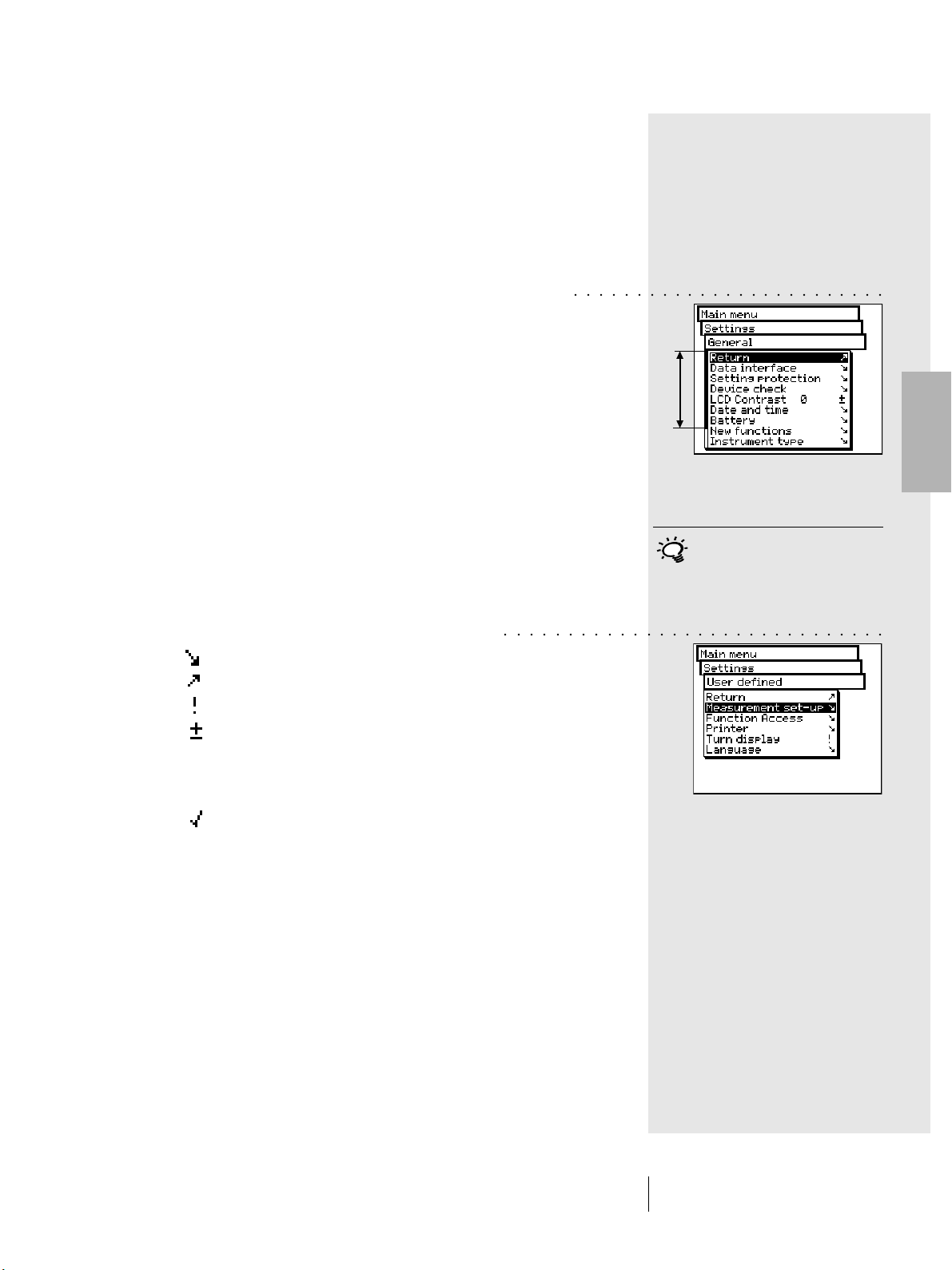
Note:
A black vertical indicator bar on the menu indicates the
current position in the overall menu. If the menu is too long
to be contained in a single page, turn the control wheel to
scroll the page and view parts of the menu not initially
displayed.
2. To confirm, press the measurement pad.
Pressing the measurement pad activates various procedures
which are indicated by different symbols displayed at the end
of a given line on the menu:
The program passes to the next lower level.
The program passes to the next higher level.
The program performs the chosen operation.
After having pressed the measurement pad, the value
preceding the symbol can be modified using the wheel,
and the new setting value can be confirmed by pressing
the measurement pad again.
This displays the current status of a setting. In this mode
it is possible to see which settings are active when
a menu is selected. A different setting can be activated
by pressing the measurement pad.
○○○○○○○○○○○○○○○○○○○○○○○○○
2
The measurement key must always
be pressed briefly, because it is
used to quit a given menu when
held down for longer (about three
seconds).
○○○○○○○○○○○○○○○○○○○○○○○○○○○○○○
SpectroEye™ 23
2 • Use
Page 24
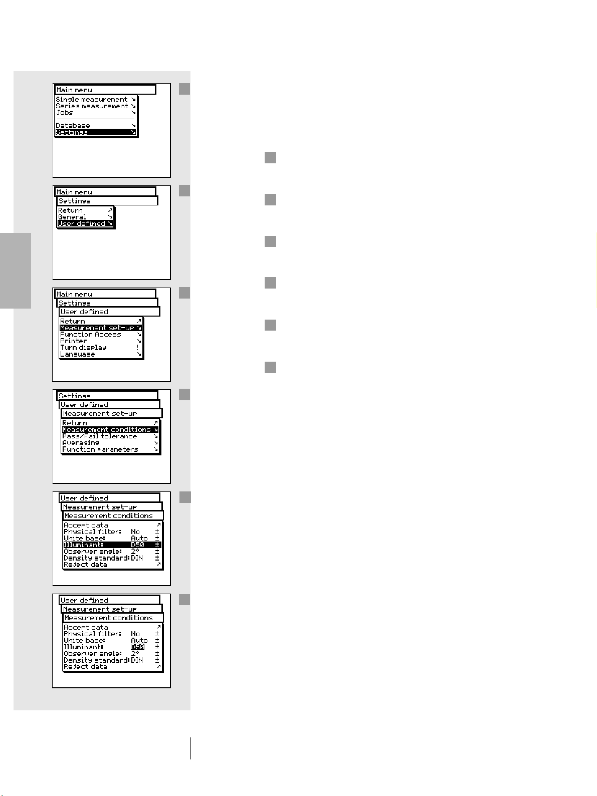
2
It is sometimes necessary to browse through different menus to
1
2
3
4
recall a given function. To avoid describing this procedure each
time in detail, this manual gives an abbreviated description.
For example, to set illuminant D65, you must proceed
as follows:
1
In the main menu, turn the wheel until the cursor bar is
on Settings, then press the measurement pad to select
the next sub-menu.
2
Turn the wheel until the cursor bar is on User defined,
then press the measurement pad again to select the next
sub-menu.
3
In this menu, turn the wheel until the cursor bar is on
Measurement set-up and press the pad again to select
the next sub-menu.
4
Turn the wheel until the cursor is on Measurement
conditions then press the measurement pad again to
select the next sub-menu.
5
Bring the cursor bar to the Illuminant menu option and
press the measurement pad. At this point the currently set
illuminant is highlighted in a dark color.
6
All the illuminant options A, C, D65, D50, Dxx, F2, F11, Fxx,
(User) can be viewed in sequence by turning the control
wheel. Turn the wheel until the desired illuminant (D65)
is displayed and press the measurement pad again to
Accept the new data setting.
The entire procedure will be described in this manual as follows:
From the main menu, select
Settings > User defined > Measurement set-up >
5
6
Measurement conditions > Illuminant
and set D65.
SpectroEye™24
2 • Use
Page 25
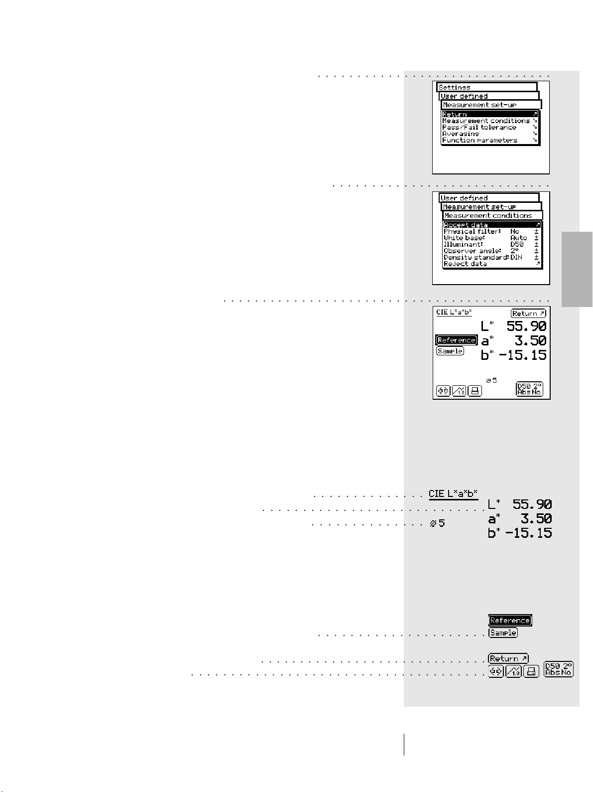
To exit the menu, proceed as follows according
○○○○○○○○○○○○○○○○○○○○○○○○○○○○○○
to the type of window:
1. If the window does not allow setting operations, exit by
selecting the Return option or by keeping the measurement
key pressed for about three seconds.
2. If the window allows for setting modifications, quit by
selecting the Accept data option to save any modifications.
If no modifications are to be made, exit by using the
Reject data option, or by keeping the measurement pad
pressed for about three seconds.
2.2.2 Measurement window
After having selected Single Measurement, Series
Measurement or Jobs from the main menu, the software leads
you to the actual functions for measurement and analysis of
values through the Measurement Window.
2.2.2.1 Measurement window structure
The measurement window contains various elements,
these are divided between display items and action fields:
• Display items
All the fields without frames are display items which change
depending on the instrument measurements, settings or
analyses.
These include:
1. Display of the current measurement function
2. Display of measurement results
3. Measurement settings, information, analysis
○○○○○○○○○○○○○○○○○○○○○○○○○○○○
○○○○○○○○○○○○○○○○○○○○○○○○○○○○○○○○○○○○○○○○○○
○○○○○○○○○○○○○○
○○○○○○○○○○○○○○○○○○○○○○○○○○○○
○○○○○○○○○○○○○○
2
• Action fields
All the fields and graphics with frames are used to activate
measurements or to enable further settings. As with the
menus, the control wheel can also be used to select the
desired active field. The selected field can then be activated
by pressing the measurement pad.
The action fields are the following:
1. Measurement field for references or samples
○○○○○○○○○○○○○○○○○○○○○
measurement
2. Measurement window exit field
3. Symbols bar
○○○○○○○○○○○○○○○○○○○○○○○○○○○○○○○○○○○○○
○○○○○○○○○○○○○○○○○○○○○○○○○○○○○
SpectroEye™ 25
2 • Use
Page 26
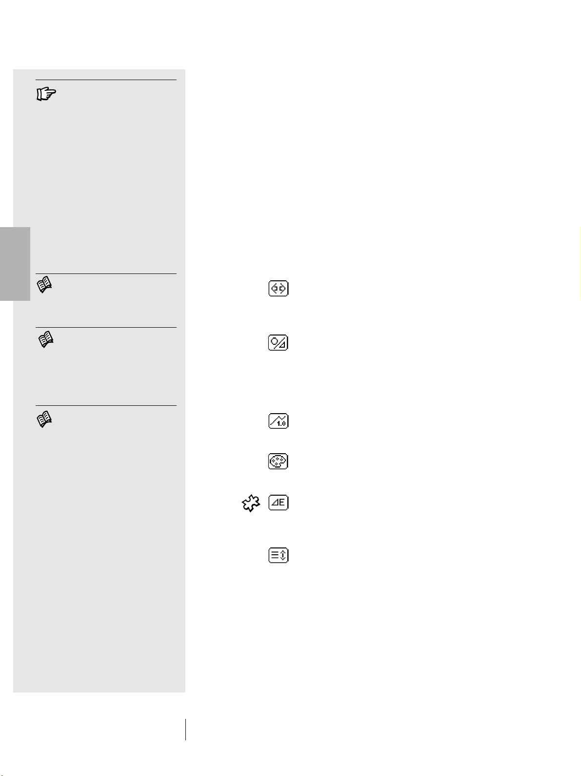
2
The function of the icons is
illustrated in detail in the corresponding points of chapter 2.4.
Read chapter 2.4.1.6
Read chapter 2.4.1.3
Read chapter 2.4.1.4
2.2.2.2 The symbols bar
The symbols bar contains the various selectable icons.
One or more icons illustrated below may not appear in the bar
for various reasons. One of these reasons is that only the icons
actually required for the selected measurement are displayed.
For example if a spectrum measurement function is selected,
the density filter icon will not appear. There are also certain icons
for optional functions which may not be installed on the
SpectroEye. These icons are only available if the optional
function has been purchased and installed. In the following
overview, these are distinguished by the puzzle symbol.
Function icons are subdivided into four groups:
1. Icons for display modification
These icons simply serve to switch the given display.
The measured values are maintained.
Measurement function
Selecting this icon modifies the measurement mode.
In this way you can switch between colorimetric and
density functions.
Absolute / Difference
If the Absolute / Difference icon is selected after
having measured the reference and the sample,
the display always switches between the absolute
value measured for the sample and the difference
between the reference and sample.
Numerical / Graphical
Use this to switch between graphical and numerical
displays of measurement values.
Filter Density
In density measurement you can choose between
manual and automatic filter selection.
E Formula
In spectral measurement, the color differences can
be calculated using different formulas. This icon
permits selection of the desired formula from the list.
Scroll
This icon is necessary if numerical representation
has been selected for reflection or density spectra.
In this case it is not possible to display all the
measurement values in a single window. Select this
icon to scroll through the list of measurement values.
SpectroEye™26
2 • Use
Page 27
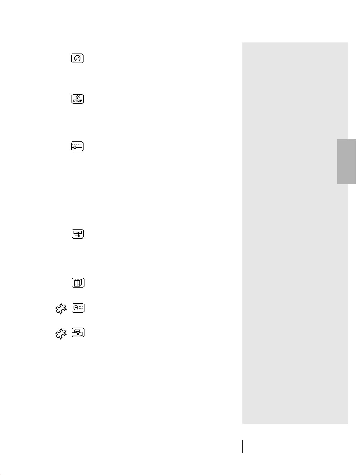
2. Icons for settings modification
Averaging
This icon must be selected if various measurements
are to be performed on a reference value or sample,
and which SpectroEye must calculate the average
value.
Stop averaging
This icon is displayed only when averaging is in
process. If during a measurement sequence the
measured values are found to diverge slightly,
the current averaging calculation can be terminated
quickly.
Function parameters
With this icon it is possible to set individual conditions
and parameters according to the selected
measurement function. These are:
• Normalised illuminants for metamerism calculation
• Dye-strength parameters
• Yule-Nielsen coefficients
• Half-tone percentage values by increment
• Scale graduation for print characteristic
• E CMC factors
• E*94 factors
Densitiy calibration
The function of this icon is to adapt the measured
values of your SpectroEye to the values of your
densitometer.
2
3. Icons for recalling database functions
Select from database
Instead of measuring a reference color, the
measurement value can be taken from a database.
Similar color
This icon must be selected if the SpectroEye has to
search in a database for the nearest measured value.
Recipe
If a reference has been selected from one of the
color guides, the standard recipe in the instrument
memory can be displayed using this icon.
SpectroEye™ 27
2 • Use
Page 28
2
Read chapter 2.4.2.4
Read chapter 2.4.2.2
Read chapter 2.4.2.1
Read chapter 2.4.3.3
Read chapter 2.4.1.5
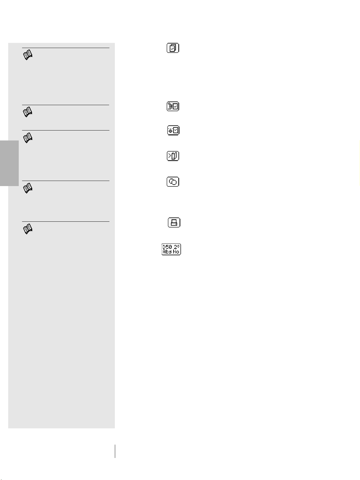
Select Reference
This icon is used to modify jobs or measurement
series for which various references have been
defined. This function determines which reference
is assigned to a sample. The assignment may be
manually defined or performed automatically by
the SpectroEye.
Modify reference
Within a given job or series, this icon permits creation
of new references or modification of existing ones.
Reference parameters
This icon is used to set a new name and a new
measurement tolerance for a reference.
Save in database
This icon is used to save a measured reference into
a created reference library.
Sample
This icon allows you to scroll through the samples
created within a job or to cancel them.
4. Other icons
Print
The various print options can be selected using
this icon.
Special icon: Measurement conditions
This icon allows the measurement conditions
to be modified.
SpectroEye™28
2 • Use
Page 29
2.3 Initial settings
When working with the SpectroEye, modification of some basic
settings are rarely done or never need to be performed. Many of
these default settings directly influence measured results, so
these settings must be reviewed immediately after deactivating
the transport protection!
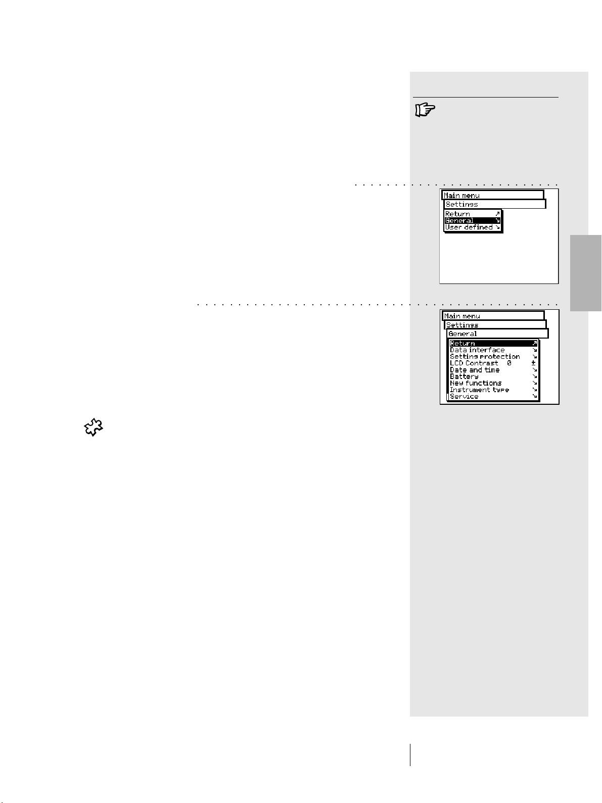
The basic settings can be found in the main menu under the
Settings option. These are subdivided into General and User
defined settings. General settings are global i.e. even if the
SpectroEye will be configured for several users, these settings
will apply to all. These are maintained until they are explicitly
modified. User defined settings refer to specific applications.
If the SpectroEye is subsequently configured for various users,
these can be independently configured for each user.
2.3.1 General settings
From the main menu, first select:
Settings > General
The following settings can be modified:
• Data Interface
• LCD contrast
• Date and time
If the basic settings are not made
immediately, be sure to at least
check them before beginning a job.
○○○○○○○○○○○○○○○○○○○○○○○○○○
○○○○○○○○○○○○○○○○○○○○○○○○○○○○○○○○○○○○○○○○○○○○○
2
The remaining settings, such as:
• Setting protection
• Battery
• New functions
• Instrument type
• Service
• Transport protection
do not need to be defined immediately and can be reviewed
at a later time.
SpectroEye™ 29
2 • Use
Page 30
○○○○○○○○○○○○○○○○○○○○○○○○
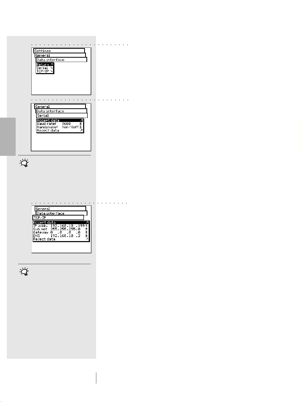
2.3.1.1 Data interface
In order to correctly make the serial connection to the printer,
a computer, or to the Ethernet connection of the computer or
network, the interface parameters must be correctly configured.
The following is a description of the variations offered by the
Menu options:
Settings > General > Data interface
2
○○○○○○○○○○○○○○○○○○○○○○○○
These settings must match those
of the connected device. Please
check the corresponding instructions
in the manual provided by the device
or software supplier. The default
settings are: Baud rate = 9600 and
Handshake = Xon/Xoff.
○○○○○○○○○○○○○○○○○○○○○○○○
• To define the parameters for serial transmission between
the SpectroEye and the printer or PC, select the Serial
option and proceed as follows:
1.First set the correct transmission speed using the
Baud rate option.
2.Then under Handshake, select
- No
- Xon/Xoff
- Hardware
3.Save settings with Accept data.
• To connect the SpectroEye through an Ethernet
interface to the Internet or a company Intranet,
select the TCP/IP option and configure it as follows:
1.Set the sequence of correct addresses for:
- IP addr.
- Sub net
- Gateway
- DNS
2.Save settings using Accept data.
To find out whether settings other
than the default values are required,
contact your system administrator.
SpectroEye™30
2 • Use
Page 31
2.3.1.2 LCD contrast
To adjust the LCD contrast to ambient lighting
○○○○○○○○○○○○○○○○○○○○○○○○○○○○○○○
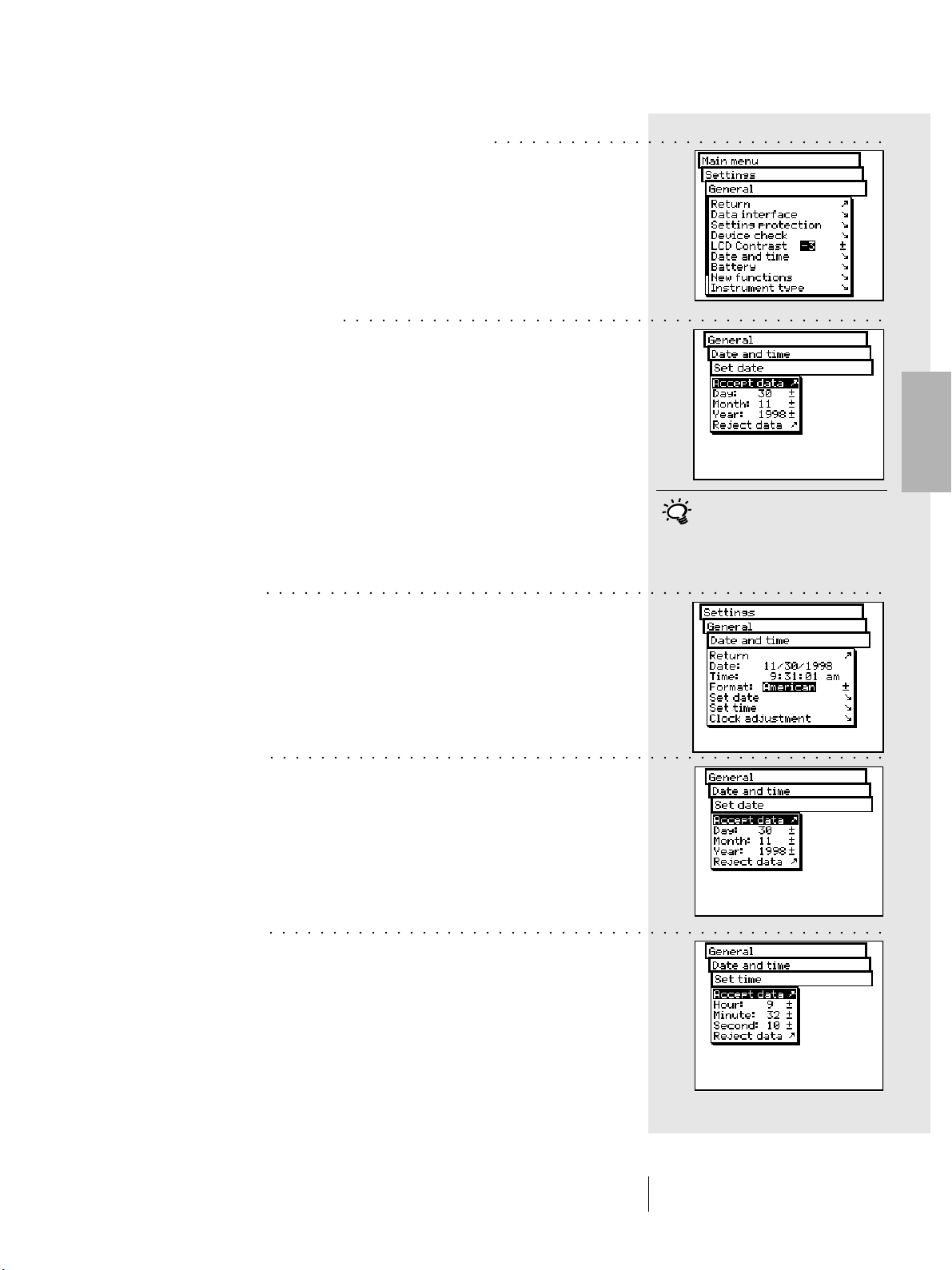
conditions, from the main menu, select:
Settings > General > LCD contrast
To get the best contrast, select one of the values
within the scale. The change is immediately visible
on the LCD.
2.3.1.3 Date and time
○○○○○○○○○○○○○○○○○○○○○○○○○○○○○○○○○○○○○○○○○○○
To automatically integrate the measurement results with
the correct date and time, the SpectroEye is equipped with
a clock/calendar. Its accuracy should be checked regularly,
by selecting:
Settings > General > Date and time
The current date and time are displayed. If incorrect,
they can be modified in this menu:
• Format
○○○○○○○○○○○○○○○○○○○○○○○○○○○○○○○○○○○○○○○○○○○○○○○○○
This command sets the display format for the date. Choose
between American or European format. American format
is month/day/year, where as European is day.month.year.
• Set date
○○○○○○○○○○○○○○○○○○○○○○○○○○○○○○○○○○○○○○○○○○○○○○○○○
Select the Set date menu option. Correct the settings of:
- Day
- Month
- Year
Save the new date with Accept data.
2
Remember to correct the clock even
when changing from summer to
standard time and viceversa.
• Set time
○○○○○○○○○○○○○○○○○○○○○○○○○○○○○○○○○○○○○○○○○○○○○○○○○
Now select Set time menu option. Correct the settings of:
- Hour
- Minutes
- Seconds
Save the new time with Accept data.
SpectroEye™ 31
2 • Use
Page 32
○○○○○○○○○○○○○○○○○○○○○○○○○
If the clock runs slow, a positive
value must be entered (to speed it
up), whereas if it runs fast, this
value must be negative (to slow it
down).
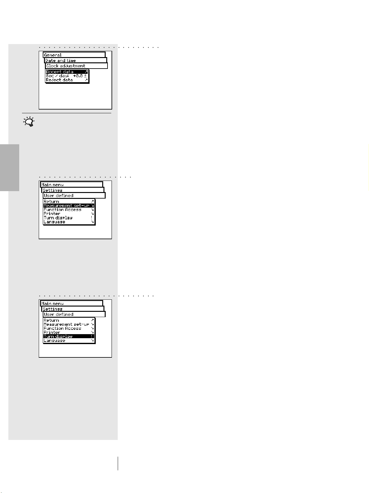
• Clock adjustment
The clock built into the SpectroEye may be running either
slightly fast or slightly slow. If the time on print-outs
is wrong, the clock can either be reset as described
previously, or its long term speed can be adjusted.
Proceed as described in the following example:
If after four weeks, you find that the SpectroEye clock
is four minutes slow.
1. Calculate the correction factor:
in 28 days, the clock lost 240 seconds, equal to
8.6 seconds per day.
2. Select Clock adjustment from the menu.
3. Select Sec/day and enter the correction factor +8.6.
4. Save the correction with Accept data.
2
○○○○○○○○○○○○○○○○○○○
○○○○○○○○○○○○○○○○○○○○○○○○
2.3.2 User defined settings
From the main menu, select:
Settings > User defined
Make the following settings:
• Turn display
• Printer
• Measurement set-up
The settings relating to:
• Function access
• Language
will be addressed later in this manual.
2.3.2.1 Turn display
The SpectroEye is designed to be used with one hand.
On delivery from the factory, it is set for use with the right hand.
So that left-handed people may also use the SpectroEye with
ease, the displayed data can be rotated.
From the main menu, select
Settings > User defined > Turn display
The display on the LCD is immediately rotated.
SpectroEye™32
2 • Use
Page 33
2.3.2.2 Printer
Measurement results can be sent directly to a printer,
○○○○○○○○○○○○○○○○○○○○○○○○○○○○
without the need of a computer. In such cases the printer
is connected directly to the SpectroEye through the serial
interface port. To obtain a correct print-out, it is necessary
to give the SpectroEye specifics about the printer to be used.
Always follow the indications given
in the printer manual and read the
instructions for connecting the
SpectroEye to a printer in chapter
1.2.3.5 to 1.2.3.6.
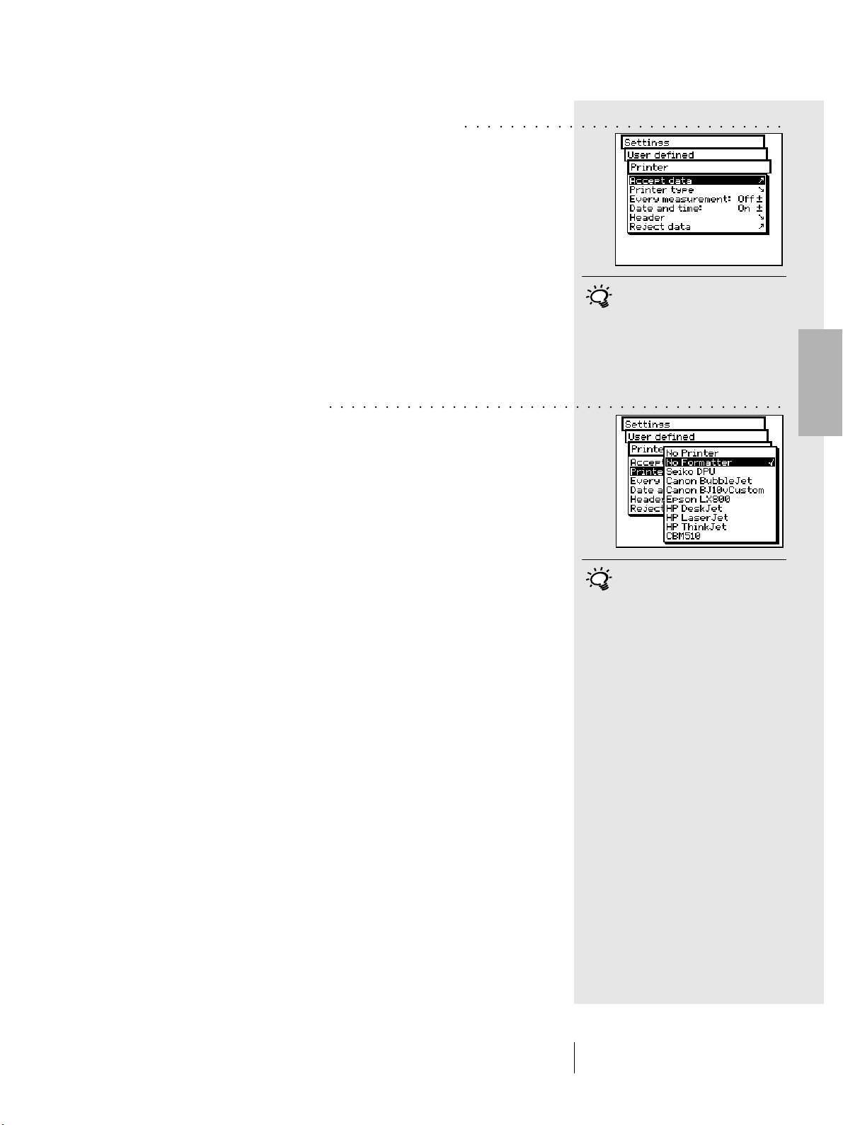
From the main menu, select
○○○○○○○○○○○○○○○○○○○○○○○○○○○○○○○○○○○○○○○○○
Settings > User defined > Printer
and proceed as follows
1. First, select the Printer type option and then the model
of printer to use.
Available printers:
• No printer
• No formatter
• Seiko DPU
• Canon BubbleJet
• Canon BJ10vCustom
• EPSON LX800
• HP DeskJet
• HP LaserJet
• HP ThinkJet
• CBM510
2. If you require the date and time to be entered automatically
with the print-outs, select Date and time menu option
and set the displayed value to On.
3. The printer protocol heading can be defined by selecting
the Header menu item. Enter the text which is to appear
in the printer protocol; 5 lines are available.
4. Save settings using Accept data.
2
If your printer does not appear on
the list, consult its manual to see
whether it is compatible with one
of the printers listed. Otherwise,
select the No formatter setting.
SpectroEye™ 33
2 • Use
Page 34
2
○○○○○○○○○○○○○○○○○○○○○○○○○
Here you should select the most
frequently used settings in normal
operation. In this way it is possible
to guarantee a consistency to the
color measurement, which should
only be modified occasionally to
meet the application requirements.
○○○○○○○○○○○○○○○○○○○○○○○○○
2.3.2.3 Measurement set-up
Settings of Measurement set-up menu are considered the
default ones. They are always taken as basic settings when
you are working with a Single measurement or when you create
a Series measurement or Jobs.
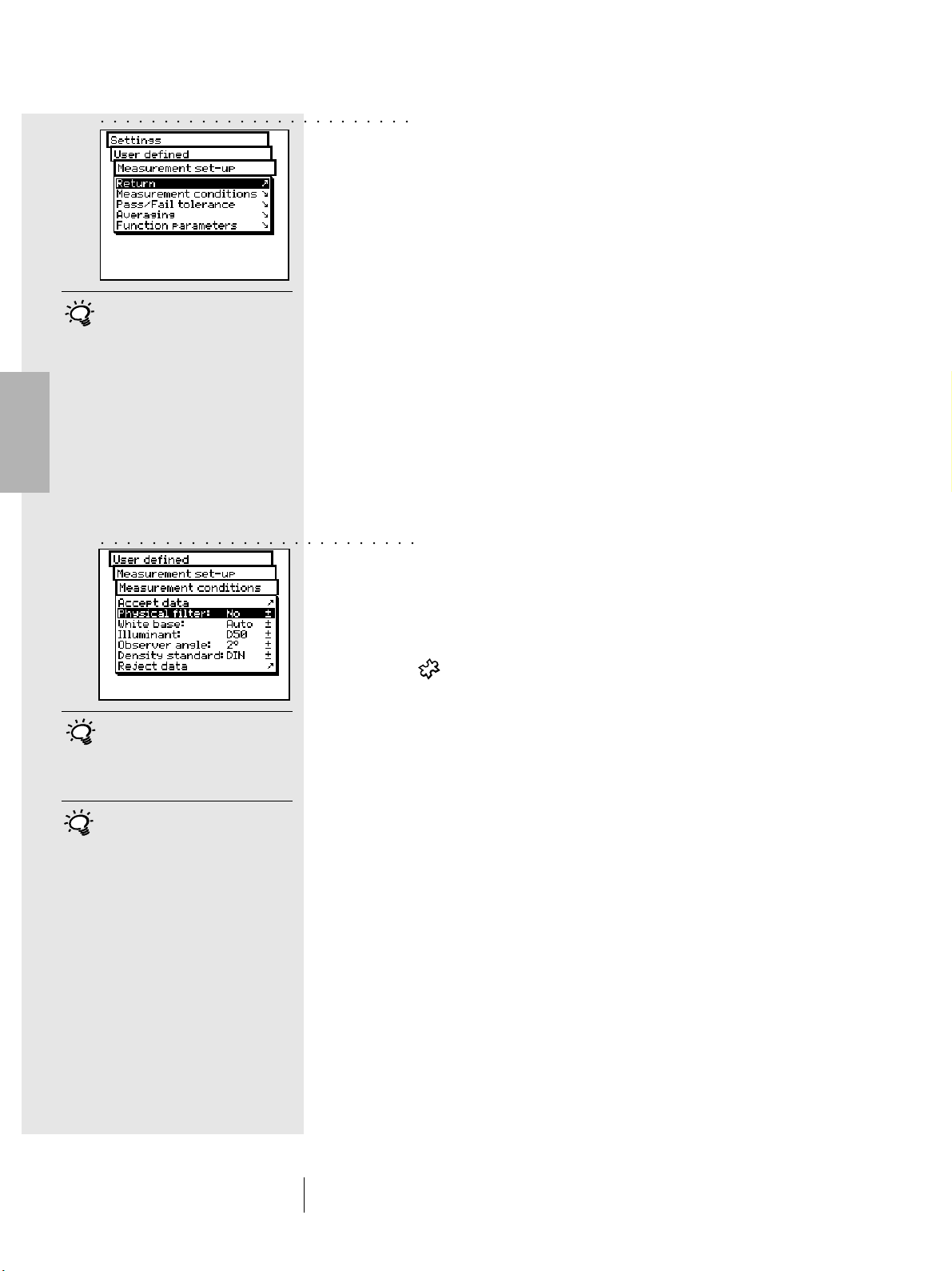
To define these basic settings, starting from the main menu
you must select
Settings > User defined > Measurement set-up
and then:
• Measurement conditions
All settings of the Measurement conditions menu should
be made with great care as they affect the measurement
results. They can be checked on the symbol bar of the
measurement window and can be changed to meet the
application requirements, at any time.
The measurement conditions include:
- Physical filter
Determine if the measurement must be performed
using a physical filter.
The following filter settings are available
-No -> without filter
- Pol -> polarisation filter
- D65 -> Average North Sky daylight
- UVCut -> UV suppression
If you don't know which filter is
to be used, select NO for spectral
measurements and POL for
densitometric ones.
In practice the densitometric
analyses are based on paper
(Pap setting) while the spectrophotometric ones are based on
the integrated white reference
(Abs setting). It is advisable to
select the Auto setting and
change it only in special cases.
- White base
For a correct spectral or density measurement,
the corresponding white base must be defined.
The following settings are available
- Auto -> automatic selection
- Pap -> paper white
- Abs -> absolute white
If you select Pap, as white base, all subsequent
measurements will refer exclusively to the printed ink layer,
while the paper color effect will not be included. To obtain
the basic base reference you should always measure the
paper used.
If you select Abs, besides the printed ink layer, the
measurement will also include the paper effect.
Here the integrated white reference will be used as
the white base.
SpectroEye™34
2 • Use
Page 35
If you select Auto, SpectroEye will automatically use the
white base usually adopted for the selected function.
For densitometric functions, this is the white base of paper,
while for spectrophotometric functions it is the absolute
white base.
- Illuminant
To calculate the special color values, select the desired
normalised illuminant.
The most commonly used normalised illuminants are
immediately available:
A, C, D65, D50, F2, F7, F11
The normalised illuminants of D and F series must be
set-up using the Dxx and Fxx menu items. When you
perform this selection, an additional menu line appears,
where you can select the desired color temperature.
Here the following illuminants are available:
Fxx: F1 to F12
Dxx: D30 to D300
- Observer angle
When analysing the colorimetric values, the calculation
and consequently the result depend on the definition of
the observer angle.
In this menu line you must select the observer angle,
normally between 2° and 10°.
Usually the normalised illuminan
for the Graphic Arts industry used
in the USA is D50 while in Europe
it is D65.
2
You can freely select one of the two
settings. It is extremely important
that for color comparison the selected
setting is always kept constant.
- Density standard
If you wish to use the SpectroEye spectrophotometer
also as a densitometer, you must define which density
standard to operate with.
In this menu line select either:
DIN, DIN NB, ANSI A, ANSI T, SPI
Save your settings in the Measurement conditions menu
using Accept data and proceed with:
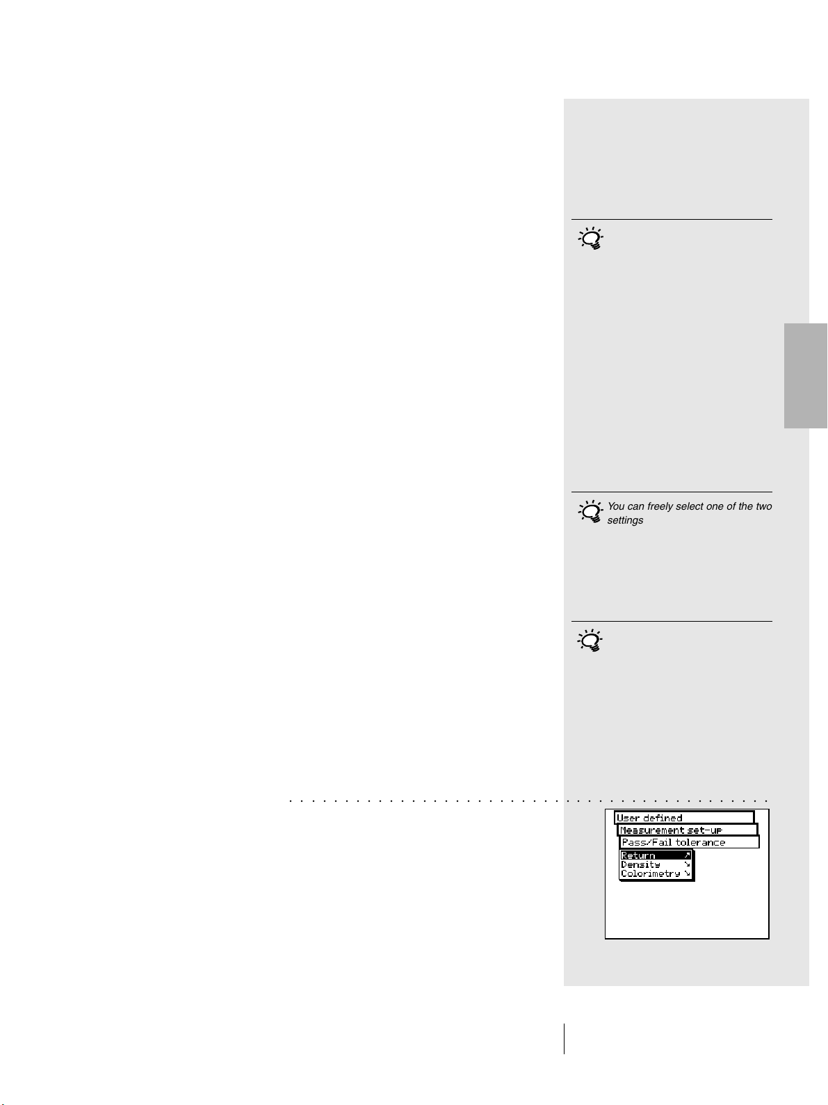
• Pass/Fail tolerance
○○○○○○○○○○○○○○○○○○○○○○○○○○○○○○○○○○○○○○○○○○○○
When you work with Series measurements or Jobs,
immediately after the reference and sample measurement,
you obtain an evaluation in terms of pass/fail.
The measured values are included in (Pass) or excluded
from (Fail) based on the tolerance values defined in
this menu.
Normally the density standard used
in the USA is ANSI T while in
Europe it is DIN. As a guide line it
is advisable to select the settings
corresponding to the set of physical
filters available on the densitometer,
should one already be in use.
SpectroEye™ 35
2 • Use
Page 36
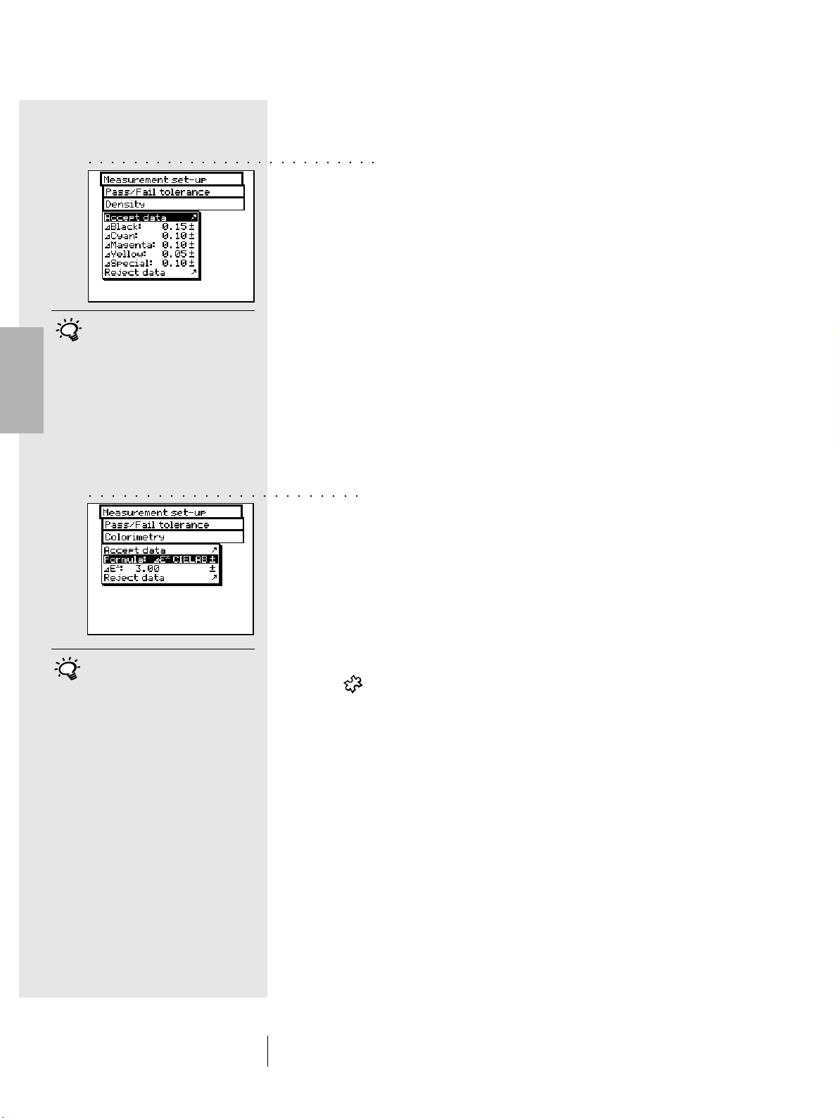
The tolerances are defined separately for densitometric and
spectral measurements as follows:
2
○○○○○○○○○○○○○○○○○○○○○○○○○○
The tolerances set-up in this menu
must be considered only as a first
recommendation. In general, it is
advisable to choose tolerance limits
based on customer needs and
product requirements.
○○○○○○○○○○○○○○○○○○○○○○○○
Starting from the Measurement set-up menu, select
Pass/Fail tolerance > Density
Enter the sequence of tolerances corresponding to the
maximum densities of the process colors. The tolerance
values indicate how much the solid density value of a
measured sample can shift from the solid density of the
reference.
Example:
The reference for cyan has been measured with a solid
density of 1.55. The tolerance value was set-up to +/- 0.10.
All the measured samples are within the density range
of 1.45 and 1.65 i.e. within the allowed tolerance. Therefore,
in the measurement window Pass will be displayed.
If the solid density is higher or lower than such limits,
Fail will be displayed.
Next, starting from the Measurement set-up menu, select
Pass/Fail tolerance > Colorimetry
In the Formula: menu line select the formula you want to use
to define the tolerance.
The following formulas and tolerance settings are available:
The tolerances set-up here must
be considered only as a first
recommendation. It is advisable
to tune tolerance limits based
on customer needs and product
requirements.
Supplied with the base - L*a*b*
instrument: - E* CIELAB
Options: - E CMC, E FMCII, E*94
- E* CIELUV
-E mg
- E Hunter Lab
As soon as you have chosen one of the above formula, the
corresponding parameters are displayed in one or more menu
lines. When the data entry procedure is completed, save the
tolerance values using Accept data.
All the subsequent Pass/Fail evaluations will refer to this formula
and to the tolerances defined here. The Pass/Fail evaluation is
displayed only if the corresponding measurement function has
been selected.
SpectroEye™36
2 • Use
Page 37
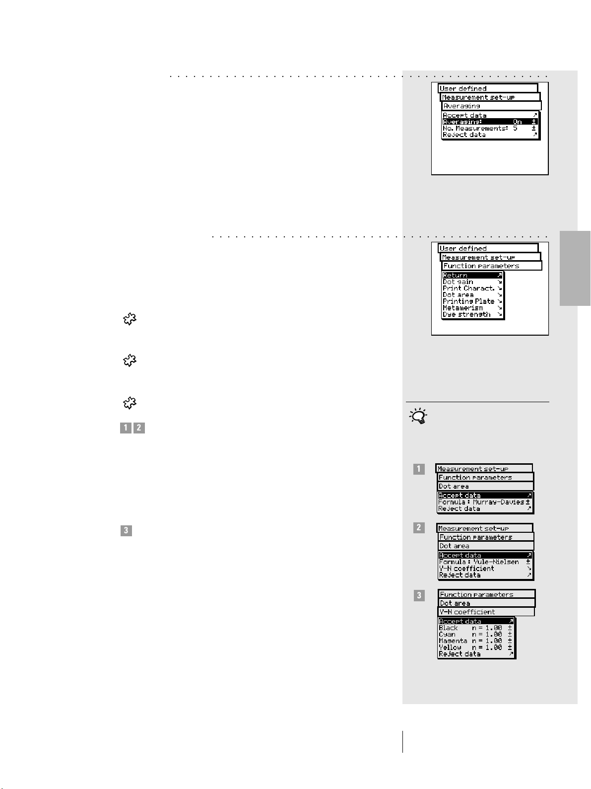
• Averaging
○○○○○○○○○○○○○○○○○○○○○○○○○○○○○○○○○○○○○○○○○○○○○○○○
For non-homogeneous samples and references SpectroEye
is able to calculate the average of different measurements.
Starting from the Measurement set-up menu, select
Averaging.
Here you can activate or de-activate automatic averaging,
as well as set-up the number of measurements to be taken
for each average. If the averaging function is activated,
an icon appears on the symbol bar of the measurement
window, which allows these settings to be changed.
• Function parameters
○○○○○○○○○○○○○○○○○○○○○○○○○○○○○○○○○○○○○○○○○○○
Some measurement functions are based on parameters which
must be adjusted to individual working conditions.
To modify these, starting from the Measurement set-up menu,
select Function parameters.
Enter each parameter used for the following functions:
- Dot gain
Enter the screen percentage value provided in the
color bar halftone fields for dot gain measurement.
- Print characteristic
Set-up the halftone levels from which the print
characteristics must be created.
- Dot area
For dot area calculation you may use the
Murray-Davies and Yule-Nielsen formulas.
1 2
While for the Murray-Davies formula the degree
of light optical absorption is predefined, in the
Yule-Nielsen formula this can be adapted for
different conditions.
First, select the Formula: menu item, and choose
the formula to be used for calculation. If you choose
the Yule-Nielsen formula, another line appears within
the menu where you can set the Y-N coefficient.
3
Here the “n” values for black, cyan, magenta and
yellow are entered.
2
Normally the Murray-Davis formula
is used. The Yule-Nielsen formula
should only be used in special cases,
i.e. to determine the physical area
coverage.
1
2
SpectroEye™ 37
2 • Use
3
Page 38
2
○○○○○○○○○○○○○○○○○○○○○○○○○○
The recommended settings for the
printing industry are: l=2 and c=1.
The recommended settings for the
printing industry are: kL=1, kC=1
and kH=1.
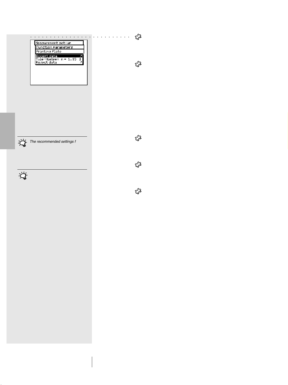
- Printing plate
When measuring the printing plate, to determine
the physical dot area coverage of your printing plate,
set the Yule-Nielsen factor.
- Metamerism
By determining the metamerism index you define
the mutual color modification of two colors when
the illuminant changes. The first illuminant used is
that defined within the
Settings > User defined > Measurement set-up >
Measurement conditions > Illuminant
menu.
Enter the test illuminants for which the color changes
for the first illuminant must be determined.
You may define a maximum of three test illuminants.
- E CMC
In order to calculate the color difference using
CMC, you must enter the correction factors for
brightness (i) and chroma (c).
- E*94
To calculate the color difference using to E*94
you must enter the correction factors for brightness
(kL), chroma (kC) and hue (kH).
- Dye strength
To determine the dye strength you must first choose
one of the available calculation methods:
at max K/S, xyz weight KS and Best Match E .
Next, access the Colorant menu item, enter the type
of ink for which you wish to determine the dye
strength. You may choose Transparent ink,
Opaque ink and Textile dye.
SpectroEye™38
2 • Use
During the measurement, the symbol bar of the measurement
window shows the function parameter icon. After having selected
the corresponding measurement functions you can always
change all settings performed.
Page 39
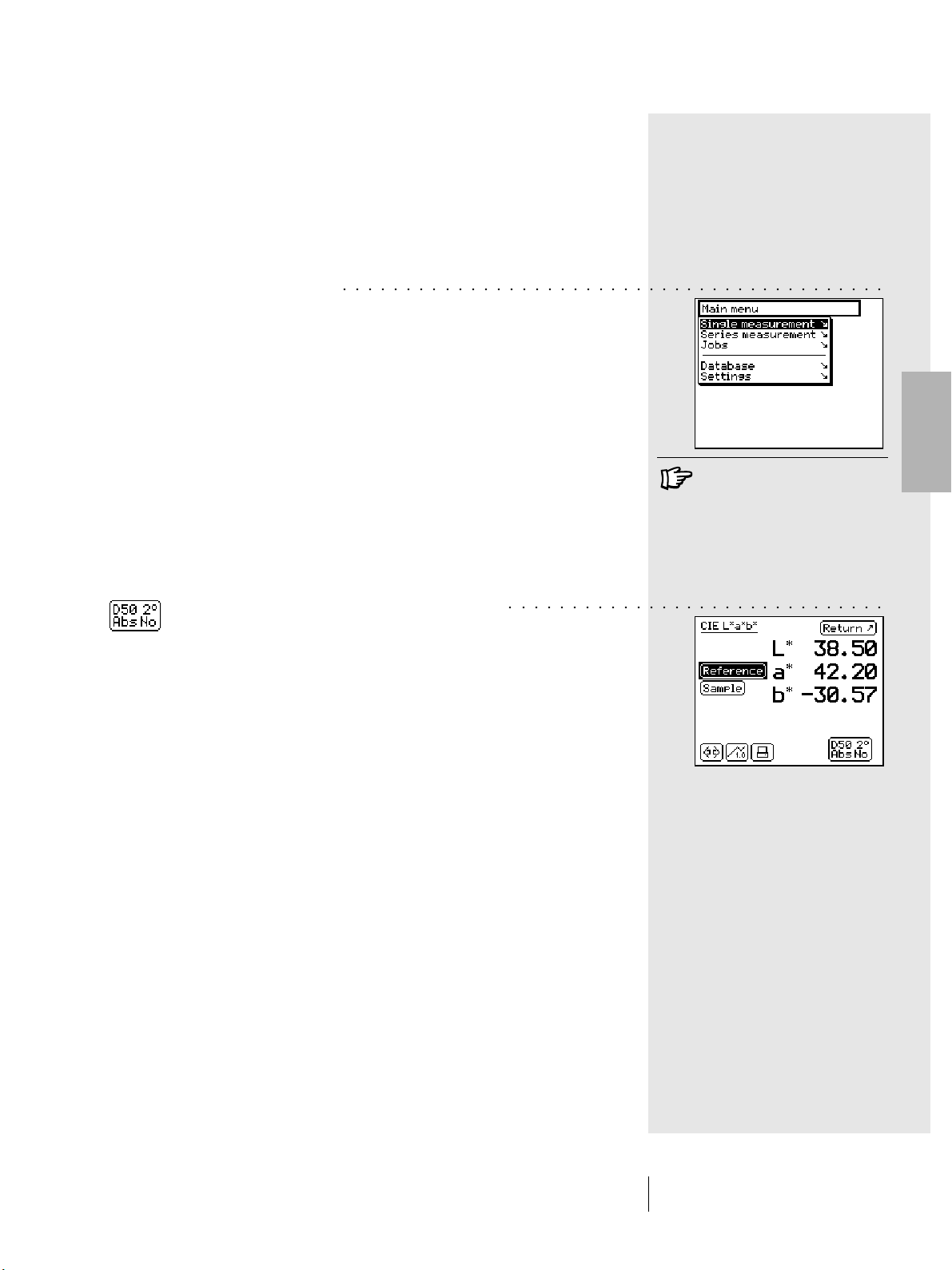
2.4 Working with the SpectroEye
This section gives a detailed description of the different
SpectroEye measurement procedures, i.e. the single measurement, the series measurement and the jobs creation. In addition,
it provides information about data management, data base
allocation and explains which settings are to be performed.
2.4.1 Single measurement
With Single measurement you can measure a single sample or
you can compare a sample with a reference without saving the
measurement results in the instrument.
Each new measurement overwrites the previous one. Two
examples are used, the spectral measurement of color with
CIELAB and the simple density measurement.They will show
how the measurement and reference sample comparisons are
performed. It is suggested the operator follow the procedures
step-by-step.
By selecting the Single measurement item from the main menu,
you immediately get the measurement window
2.4.1.1 Checking the measurement conditions
The special icon at the end of the symbol bar of the
measurement window shows the active measurement conditions.
Ensure that settings are still matching your needs. At delivery
time the SpectroEye is configured in such a way that the
measurement conditions cannot be directly changed using the
special icon. As these settings greatly affect the measurement
results they must be kept constant, especially during the
comparisons between measured values.
○○○○○○○○○○○○○○○○○○○○○○○○○○○○○○○○○○○○○○○○○○○
If SpectroEye is not in CIELAB
mode, first read section 2.4.1.6
to see how to define the
measurement functions and
set-up the CIELAB mode.
○○○○○○○○○○○○○○○○○○○○○○○○○○○○○○
2
If for technical reasons related to the application you wish to use
this icon to change settings, you can make it available through
the settings.
SpectroEye™ 39
2 • Use
Page 40
2
○○○○○○○○○○○○○○○○○○○○○○○○○
○○○○○○○○○○○○○○○○○○○○○○
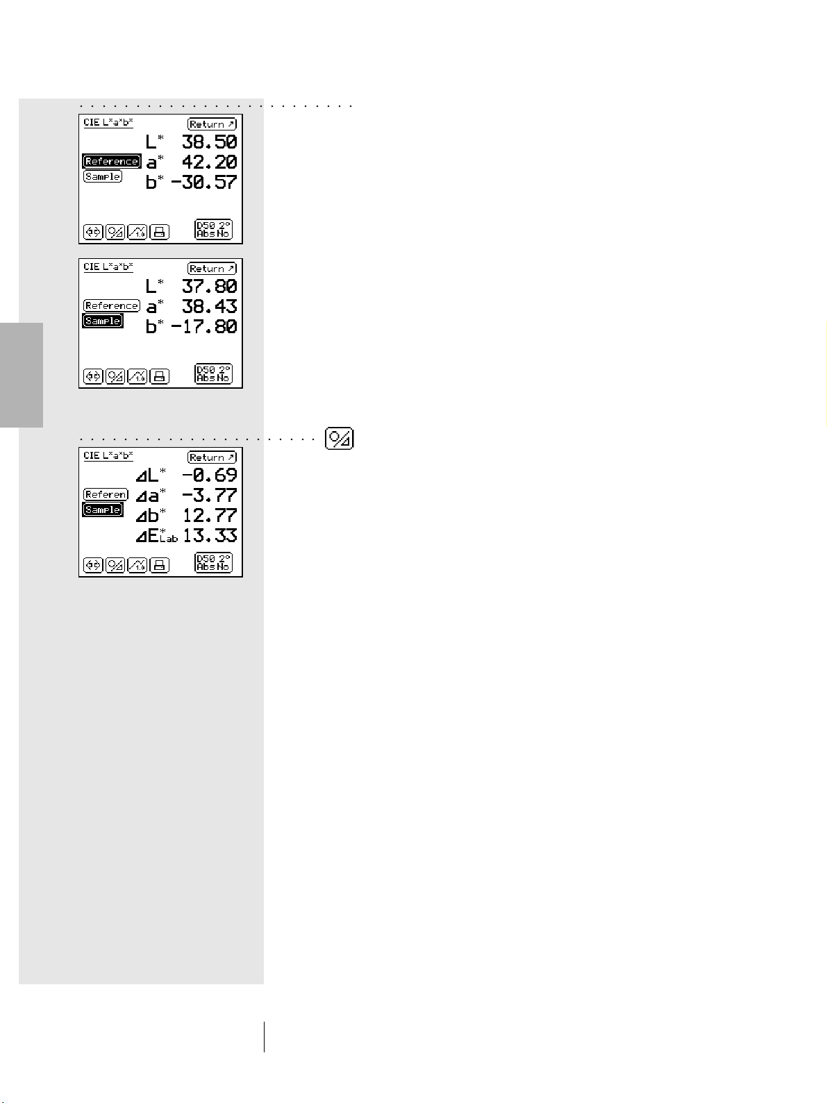
2.4.1.2 Reference and sample measurement
Using the Reference and Sample fields, perform a measurement
for each of these items. A Reference is usually intended as
an original color element, i.e. the original provided by a customer
which must be reproduced. A sample is the reproduced color
sample to be compared with the reference.
The measurement data detection sequence can be easily
selected. To do this, position the SpectroEye on the area to
ensuring that the measurement aperture is completely filled with
the color to be measured. Lay the instrument on the
measurement surface and ensure it is perfectly level and not
subject to vibrations.
The measured color values are all saved independently and
they are shown at the beginning as absolute values. If, after
the measurement, the control wheel is used to switch between
the Reference and Sample fields, the display also changes,
thus allowing the comparison of absolute values.
2.4.1.3 Comparison of measurement values
If you wish to compare the reference and the sample using the
color difference between the two measurements, the sample
display can be switched from the absolute values of the sample
to the difference values between the reference and sample.
To make this easier, you can use the Absolute/Difference icon
available on the symbol bar. When you select this icon, the
display shows the difference and, on subsequent selection of
the same icon, it will come back to the absolute value.
SpectroEye™40
2 • Use
Page 41
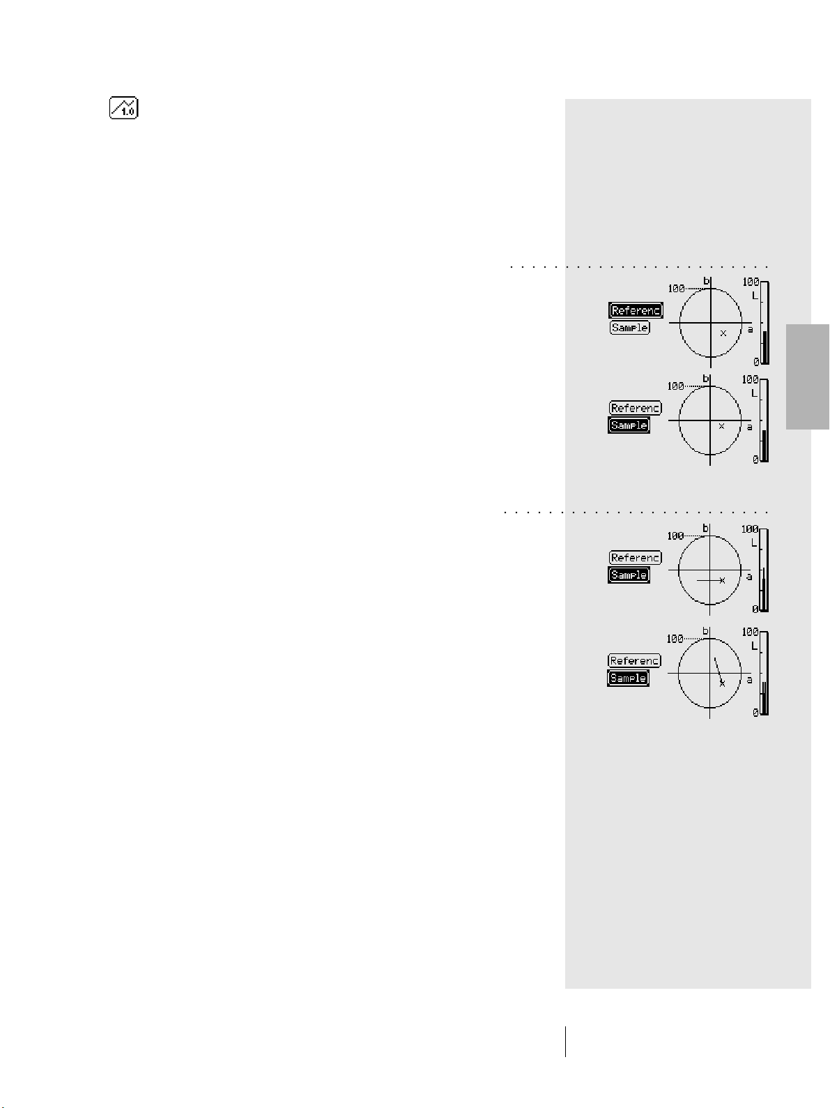
2.4.1.4 Graphic representation of measurement results
The graphic representation may be very useful to correctly
interpret the measurement results. To change between numerical
and graphical display you can use the Graphical/Numerical
icons on the symbol bar. The SpectroEye may represent both
absolute values and differences in graphical mode.
For the CIELAB function the various graphic representation
possibilities are as follows:
• Graphic representation of absolute measurement values
In numerical mode, using the absolute difference icon, first
select the absolute representation, then switch to graphic
representation using the Graphical/Numerical icon.
The graphical representation of CIELAB values shows the
CIELAB system with the green-red axis (a), the yellow-blue
axis (b) and a saturation ring with unit 100. The (x) mark inside
the representation shows the position of the measured value.
The third dimension of the CIELAB system, i.e. the brightness,
is the represented by the vertical bar on the right side of
display. The brightness value can be read according to the
length of the black bar.
○○○○○○○○○○○○○○○○○○○○○○○○
2
• Graphic representation of the color difference between
reference and sample
Using the Absolute/Difference icon, select the Difference
option for the sample.
The cross mark (x) indicates the position of the reference
item, while the line indicates the direction where the sample
diverges from the reference itself. The length of the line is
always the same i.e. it does not represent a distance between
the measurement values. In the brightness display, the
brightness of the reference is represented by the thick black
bar. If the sample is lighter than the reference, this is represented by a thinner line above the thicker one (see the top
figure). If the sample is darker than the reference, a thin light
line is shown inside the thicker black line (see the bottom
figure). This line also will always have the same length,
so it can only be used to detect the direction.
○○○○○○○○○○○○○○○○○○○○○○○○
SpectroEye™ 41
2 • Use
Page 42
The printer connection options
are described in chapter 1.2.3.5
and 1.2.3.6.
The printer to be connected, as
well as the company data which
should appear on the printing
protocol, can be defined as shown
on chapter 2.3.2.2.
○○○○○○○○○○○○○○○○○○○○○○○○○
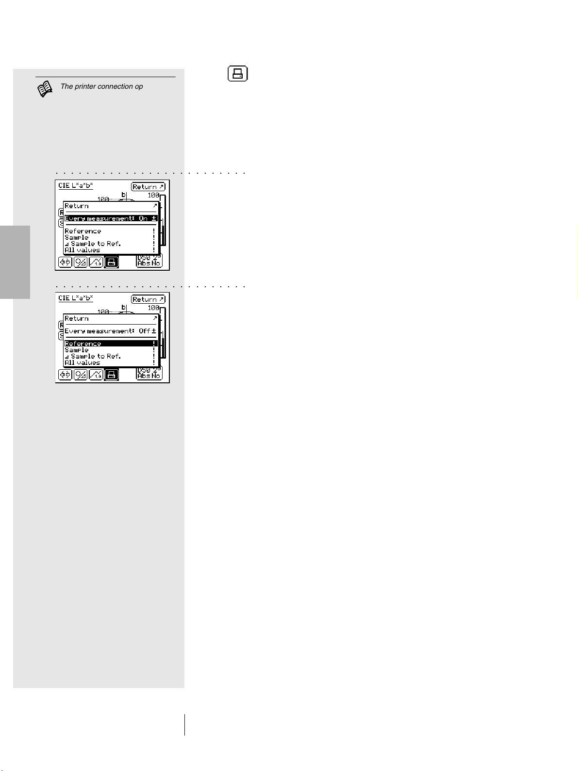
2.4.1.5 Printing the measurement values
To obtain a documentation of measurement results, the
SpectroEye may be connected directly to a printer.
If in the user defined settings a printer has already been defined,
the symbol bar shows the Printer icon.
When you select this icon, a menu appears which allows you
to choose different printing possibilities:
1. If in general you wish to print all the measurements on a
single printer, select the Every measurement menu item and
set the display to On. From then on, all the measurements
performed will be printed automatically.
2
○○○○○○○○○○○○○○○○○○○○○○○○○
2. If you wish to obtain a printed result only for particular
measurements already performed and just shown on the
screen, set the Every measurement menu item to Off and
select which of the last measured values should be printed.
The following options are available:
- Reference
- Sample
- Sample to Ref.
- All values
The printing output is determined by the current display mode.
If the SpectroEye display is set to graphical mode, both graphics
and numerical values will be printed. If the numerical display is
selected, only the measurement values will be printed.
SpectroEye™42
2 • Use
Page 43
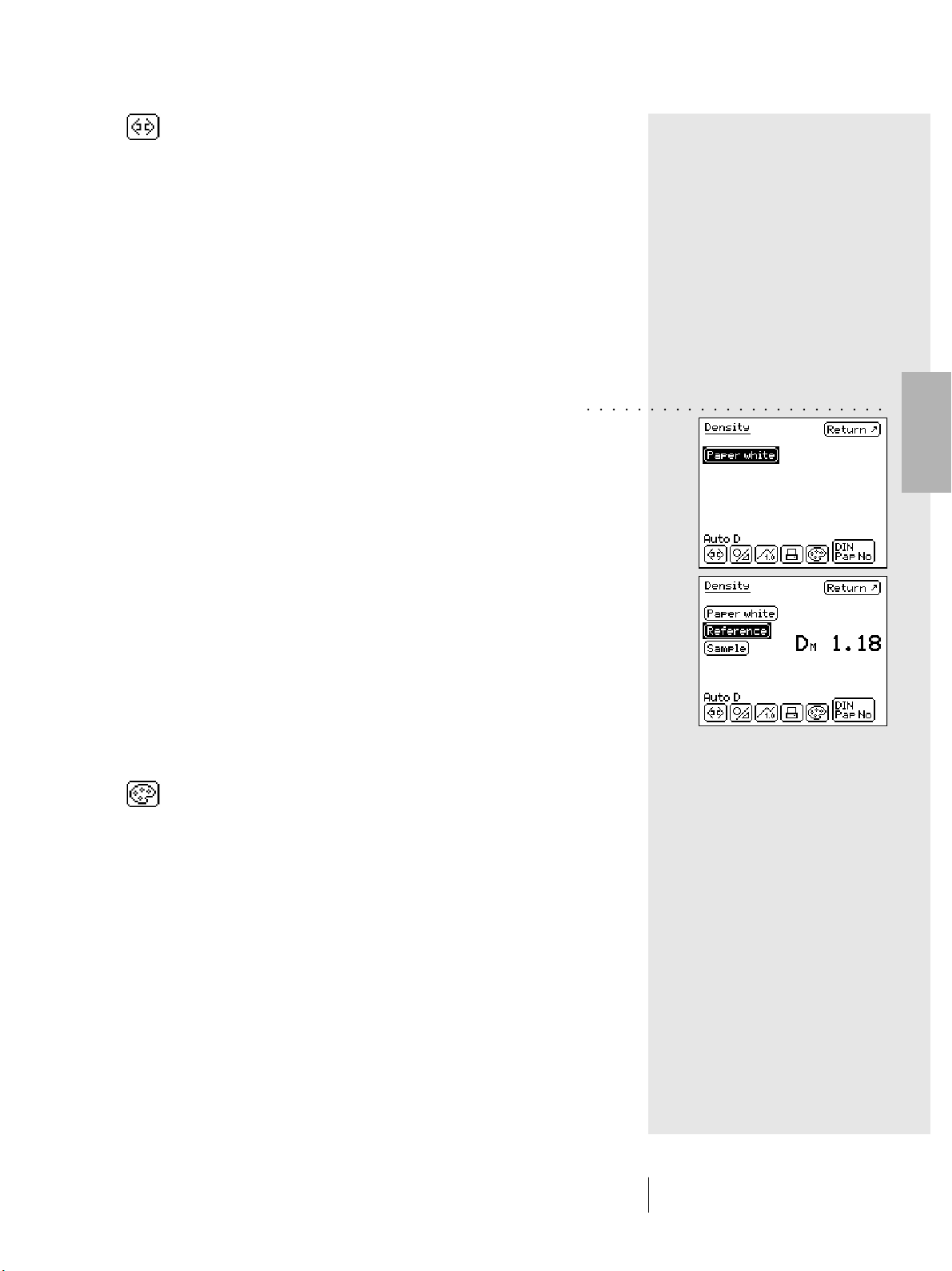
2.4.1.6 Switching between measurement functions
The SpectroEye allows the originals to be quickly and simply
analized within the measurement modes, once they have been
measured.
The SpectroEye comes with the Density and CIELAB
measurement functions. The following section gives a detailed
explanation on how to switch from CIELAB to Density functions.
Select the Measurement function icon from the symbol bar.
The displayed menu lists all the available measurement
functions. Select the Density function to reproduce the following
example.
As the densitometric measurement is normally referenced to the
white paper, when a density function is called for the first time,
the operator is requested to measure the White paper, before
the measured results are shown on display. It is not necessary,
however, to remeasure the reference or sample.
○○○○○○○○○○○○○○○○○○○○○○○○
Switching to different measurement functions is related to the
modification of displays within the measurement windows.
In this example, the display of the following elements, change:
- Measurement functions
- Measurement values
- Measurement conditions
- Display for density filter selection
It may also happen that within a different measurement function,
some icons as well measurement buttons are available, which
are still unknown.
In our example this occurs for the icon:
- Density filter
Settings such as Graphical/Numerical, Absolute/Difference
etc. are used without variations.
2
SpectroEye™ 43
2 • Use
Page 44
2
2.4.2 Series measurement
○○○○○○○○○○○○○○○○○○○○○○○○○
○○○○○○○○○○○○○○○○○○○○○○○○
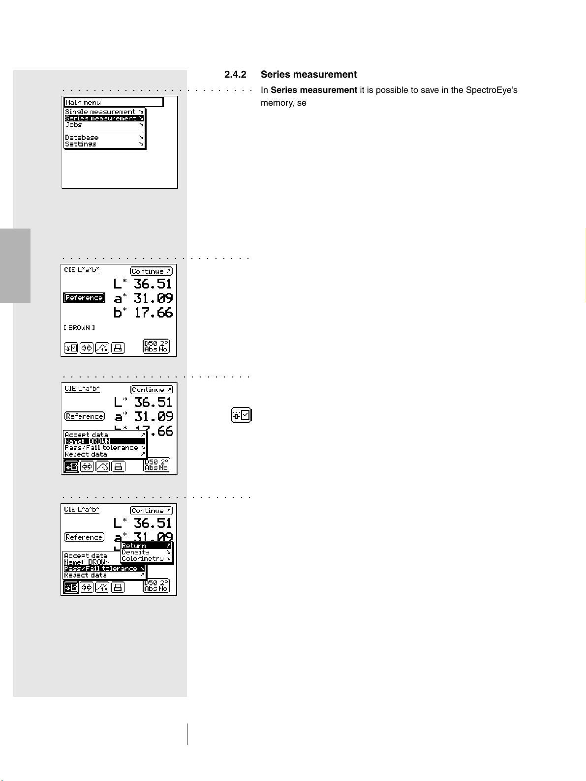
In Series measurement it is possible to save in the SpectroEye’s
memory, several references as Series. The measured sample
is either automatically or manually assigned to the related
reference. While the reference values are kept in memory
until they are deleted by the operator, the samples are overwritten for each new measurement.
To operate in Series measurement is described here using
the color measurement function of the CIELAB system.
To understand this procedure the Single measurement
section (2.4.1) should already have been reviewed.
2.4.2.1 Creating a series of references
From main menu select:
Series measurement > New measurement > New reference
A special Reference measurement window appears. This is the
window used to exclusively create and process the references.
○○○○○○○○○○○○○○○○○○○○○○○○
○○○○○○○○○○○○○○○○○○○○○○○○
First, check your measurement conditions. Next measure the
desired reference. As soon as the measurement value is taken,
a reference name assigned by SpectroEye appears, and the
Reference parameters icon is displayed in the symbol bar.
Select the icon to change the color name and to define the
tolerances for subsequent Pass/Fail evaluation.
To change the name, cancelling that proposed, use the Name:
menu item, and enter a new name.
Here you can define both the density and colorimetric tolerances
which will be used for subsequent analysis. The tolerance values
proposed here are taken from Settings in the User defined >
Standard measurement > Pass/Fail tolerance menu.
Whether these values are taken without changes or they are
modified, the settings are always saved together with the
corresponding reference. The default settings are then kept
unchanged and they will be reproposed as standard settings
for each new reference.
SpectroEye™44
2 • Use
Page 45
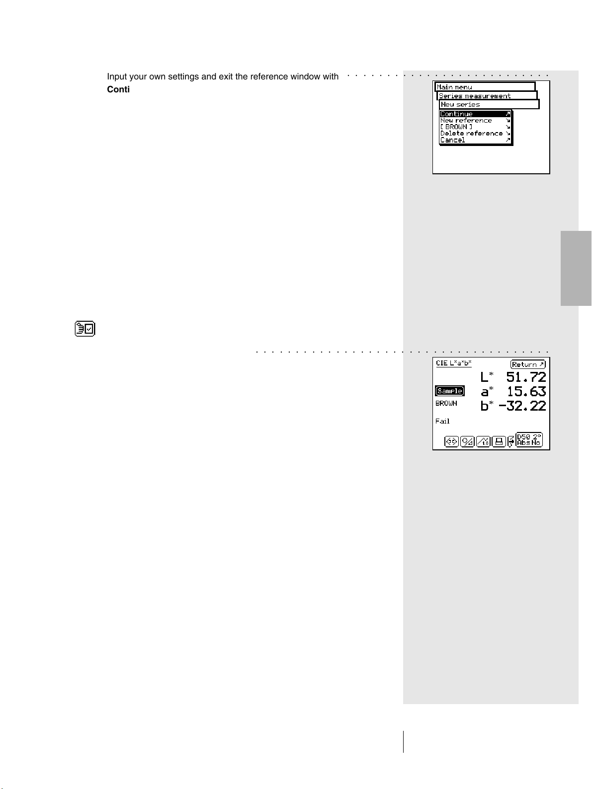
Input your own settings and exit the reference window with
○○○○○○○○○○○○○○○○○○○○○○○○○○
Continue. The measured reference is included in the New
series menu and you are requested to define another original
through New reference. Repeat the operation described above
for all references.
2.4.2.2 Additional processing and deleting of references
After assigning the last reference, a list of all available references
appears in the New series menu. If, during a reference definition,
either you forgot to enter the tolerance values, you wish to repeat
the measurement or you wish to change the name, just select
the corresponding reference menu item. Then the reference
window is selected, where you may perform the changes.
To cancel a reference from the memory, select Delete reference
from the New series menu, then select the reference name and
confirm with Yes.
Both the additional processing and the reference cancellation
may also be performed inside the measurement window.
You may switch to this window, to perform changes, using
the Modify reference icon inside the reference window.
2
2.4.2.3 Measurement of samples
○○○○○○○○○○○○○○○○○○○○○○○○○○○○○○○○○○○○○
To measure samples, select the Continue item within the
New series menu. You will switch to the measurement window.
Here, the measurement window is used primarily to measure
and analyse samples.
Measure a sample. As soon as the measurement value is
taken, this is automatically assigned to a defined reference,
the reference name is displayed and a Pass/Fail evaluation is
performed. With the measurement of a new sample the previous
measurement value is overwritten, and a reference assignment
as well as a Pass/Fail evaluation are performed.
SpectroEye™ 45
2 • Use
Page 46
○○○○○○○○○○○○○○○○○○○○○○○○○
2.4.2.4 Assigning samples to a reference
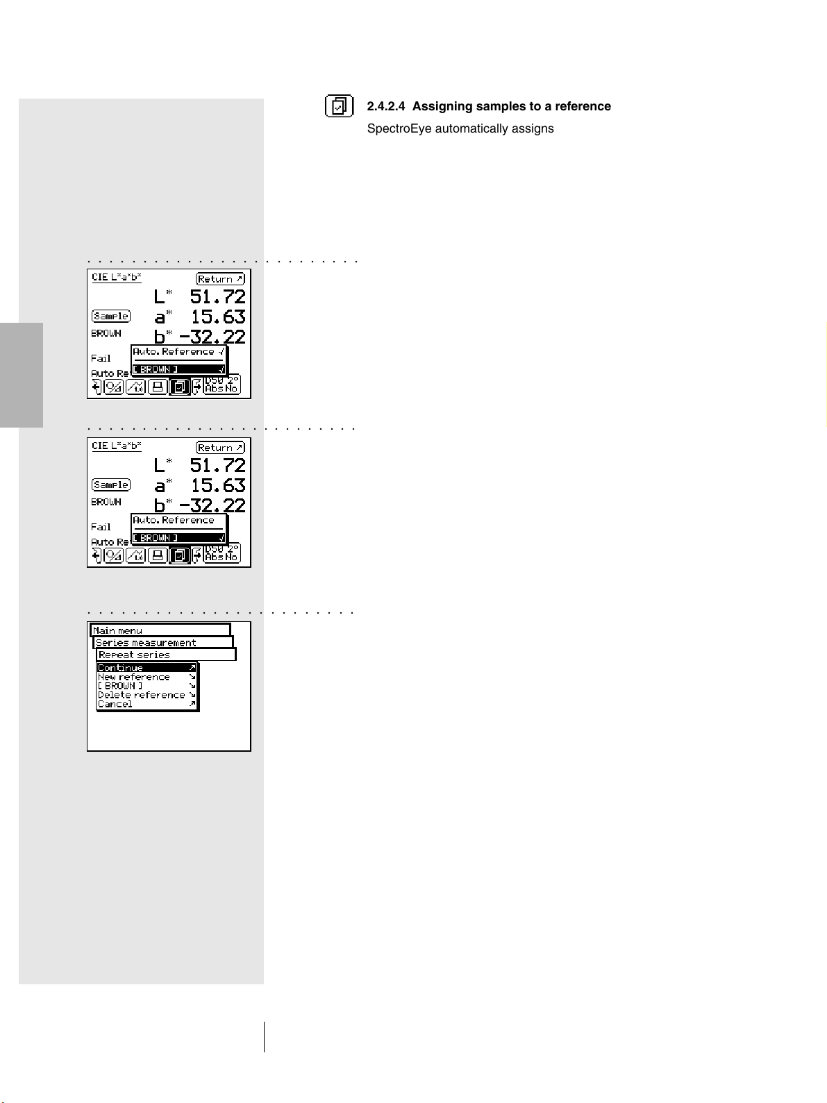
SpectroEye automatically assigns a sample to the reference
which, from the colorimetry viewpoint, is the closest to the value
of the sample. If you wish to define which reference is to be
assigned to the measured sample, use the Select reference
icon inside the symbol bar.
Besides the automatic assignment, the following options are
available:
• Short-term manual assignment
The Auto. Reference menu item is activated.
Select the name of the reference which the last measured
sample must be compared with. In this case the color
comparison with the selected reference is performed only
once. For the next measurement, the automatic assignment
will be used again.
2
○○○○○○○○○○○○○○○○○○○○○○○○○
○○○○○○○○○○○○○○○○○○○○○○○○
• Long-term manual assignment
The Auto. Reference menu item is not activated.
Select the reference name with which the sample must be
compared. In this case, all the subsequent samples will
be compared with the selected reference. The selected
assignment will be maintained until you select, another
reference, using the Select reference icon or until you
re-activate the automatic assignment using the Auto.
Reference menu item.
2.4.2.5 Repeating a series
When you leave a measurement series, you are requested
to save the series’ reference data. These reference values
are maintained until you create a New series. The new series
will be saved when you leave the new measurement series,
the old series now being overwritten.
To return to the most recently saved series, starting from
main menu select:
Measurement series > Repeat series
The series can be processed as described above, or you
can copy the references without any modification to start
the measurement of samples.
SpectroEye™46
2 • Use
Page 47
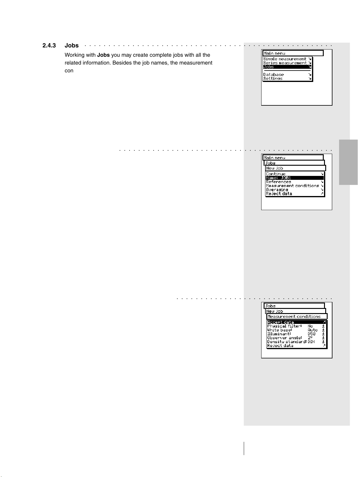
2.4.3 Jobs
Working with Jobs you may create complete jobs with all the
related information. Besides the job names, the measurement
conditions etc, all the references and all the samples measured
for this purpose are stored inside the equipment. The assignment
of measured samples to the corresponding reference may occur
either automatically or manually. All data are kept in memory until
they are expressly deleted.
The operations available with the Jobs function are described
here according to the color measurement of the CIELAB system.
To understand this procedure the Single measurement and
Series measurement sections should have already been read.
○○○○○○○○○○○○○○○○○○○○○○○○○○○○○○○○○○○○○○○○○○○○○○○○○○○○
2.4.3.1 Creating a job
○○○○○○○○○○○○○○○○○○○○○○○○○○○○○○○○○○○○○○○○○○○○○
From main menu select
Jobs > New job
and enter the job’s specific data.
The job specific data include:
- Job Name
- Job References
- Measurement conditions
- Averaging settings
These data and settings are defined separately for each job and
stored into the SpectroEye.
To enter them, proceed as follows:
• Enter the job name
The SpectroEye automatically assigns a name to the new job
which can be modified using the Name: menu option.
• Checking the measurement conditions
○○○○○○○○○○○○○○○○○○○○○○○○○○○○○○○○○
Select the Measurement conditions menu item and set-up
the desired parameter for:
- Physical filter
- White base
- Illuminant
- Observer angle
- Density standard
2
SpectroEye™ 47
2 • Use
Page 48
The settings proposed here are taken from Settings in the User
defined > Standard measurement menu. Whether these values
are taken without changes or they are modified, the settings are
always saved together with the corresponding job. The standard
settings are then kept unchanged and they will be reproposed as
standard settings for each new job.
2
○○○○○○○○○○○○○○○○○○○○○○○○○○
○○○○○○○○○○○○○○○○○○○○○○○○○○
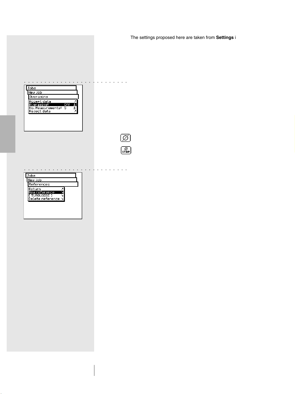
• Definition of settings for averaging
For non-homogeneous samples and references, SpectroEye
can calculate the average of different measurements,
in such a way as to ensure optimum measurement values.
Select the Averaging menu item
It is possible to activate or deactivate the automatic averaging, as well as to set-up the number of measurements to be
taken for the averaging. If the averaging function has been
activated, the Averaging icon appears in the symbol bar
of the measurement window. This allows these settings to be
changed again. Using the Stop averaging icon the averaging
operation can be turned off.
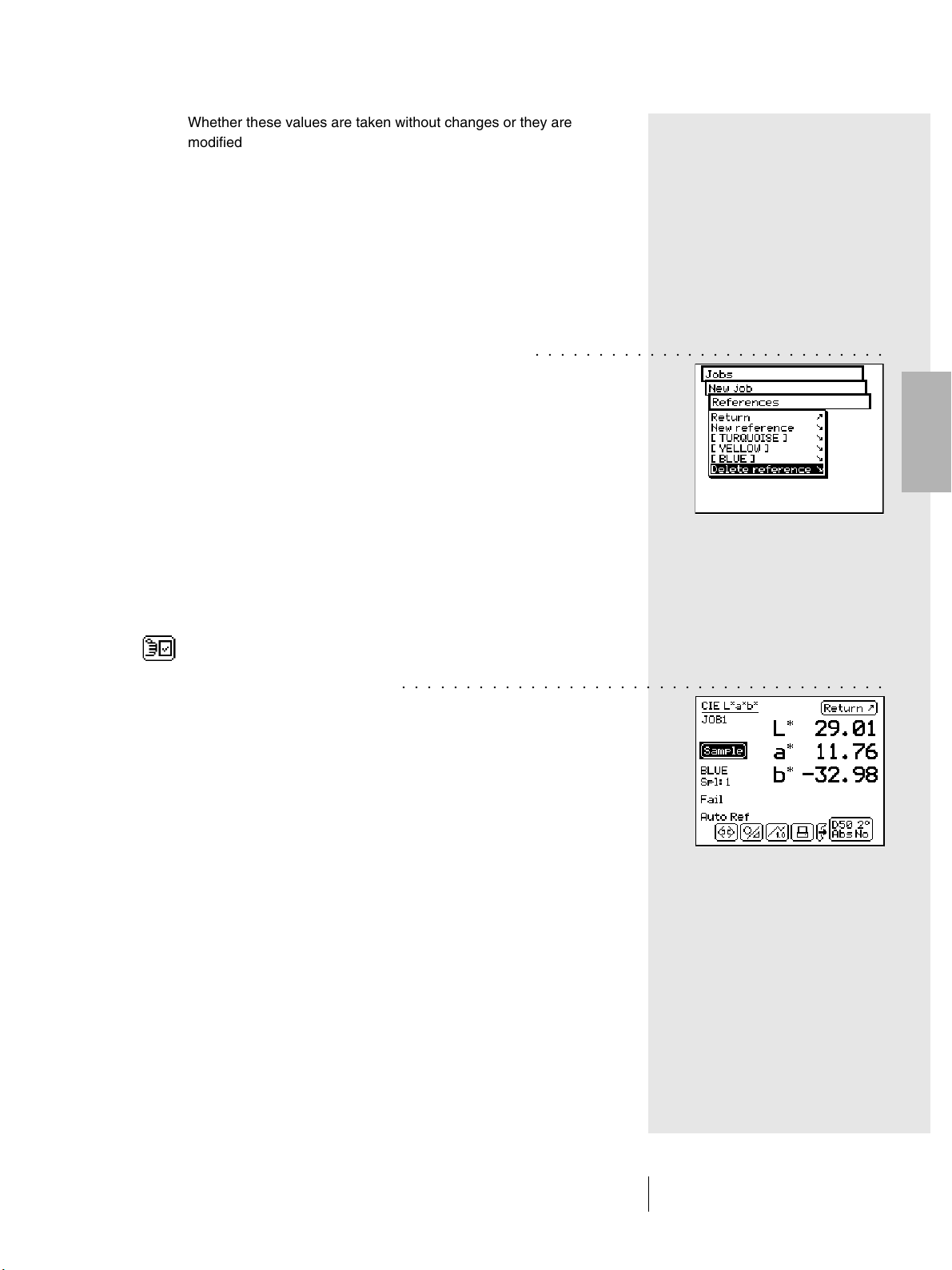
• Creating a new series of references
Select the References > New reference menu items.
The special “References” window appears. This window
is used exclusively to create and process references.
Measure the desired reference. As soon as the measurement
value is taken, a reference name assigned by SpectroEye
appears and the symbol bar shows the Reference parameter
icon.
Select this icon to change the color name and to define
the tolerances for the subsequent Pass/Fail evaluation.
Change the name by cancelling the default one, using the
Name: menu item, and enter a new name. To define the
tolerances for this reference select the Pass/Fail tolerance
menu item. You have the option to define both the density
tolerances and colorimetric tolerances for the subsequent
analyses.
It is advisable to set-up the measurement conditions
without modifying them again until the job is completed.
The tolerance values proposed here are taken from Settings
inside the User defined > Standard measurement >
Pass/Fail tolerance menu item.
SpectroEye™48
2 • Use
Page 49
Whether these values are taken without changes or they are
modified, the settings are always saved together with the
corresponding reference. The default settings are then kept
unchanged and they will be reproposed as standard settings
for each new reference.
Input your own settings and leave the reference windows
using Continue. The measured values now appear inside
the References menu and you are requested to define
another original using New reference. Repeat the described
operation for all the references.
• Additional processing and deleting of references
○○○○○○○○○○○○○○○○○○○○○○○○○○○○
After the definition of the last reference, a list of all available
references appears in the References menu. If, during
a reference definition, you forgot to enter the tolerance
values, you wish to repeat the measurement or you wish
to change the name again, just select the corresponding
reference menu item. Then the reference window is selected,
where you may perform the changes.
To delete a reference from the memory, select Delete
Reference from the Reference menu, then select the
reference name and confirm with Yes .
Both the additional processing and reference cancellation
may also be performed inside the measurement window.
You may switch to this window, to perform changes, using
the Modify reference icon inside the reference window.
2.4.3.2 Measurement of samples
○○○○○○ ○○○○○○○○○○○○○○○○○○○○○○○○○○○○○○○○
To measure samples, select the Continue item within the
New job menu. The measurement window will appear.
The measurement window is used mainly to measure
and analyse samples.
Measure a sample. As soon as the measurement value is taken,
this is automatically assigned to a defined reference, the
reference name is displayed and a Pass/Fail evaluation is
performed. The measured samples are numbered with a
progressive number, which may be read on the display under
the reference name. With the measurement of a new sample,
the previous value is saved to the jobs database. The new
measurement value replaces the previous one on the display.
The assignment of the new sample to a reference,
the Pass/Fail evaluation and the sample numbering are then
performed.
2
SpectroEye™ 49
2 • Use
Page 50
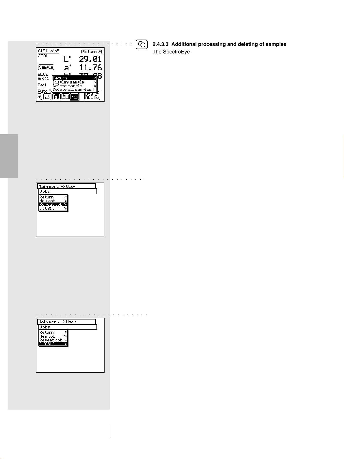
2
○○○○○○○○○○○○○○○○○○○○○
○○○○○○○○○○○○○○○○○○○○○○○○
2.4.3.3 Additional processing and deleting of samples
The SpectroEye stores all the samples measured within a job.
When a series of samples have been taken they can be
displayed and deleted, as desired. To do this select the Sample
icon within the measurement windows.
If you wish to display a given sample, select the menu items
Display sample > Sample and then the numbers of the desired
samples. As soon as the selection is confirmed by means of
Display, the measurement value with all the corresponding data
appears in the measurement window.
2.4.3.4 Remeasure a job
When leaving a job, you will be requested to save the job data.
The saved jobs are maintained until they are deleted by the
operator using Database > Jobs from main menu.
Besides creating a new job you have two more possibilities
which allow you to get data from already existing jobs:
• Processing a job as repetition
With a job repetition, a copy of an already saved job is created
and called. In this function, all the job specific data are taken
and made available, i.e.:
- Name
- References
- Measurement conditions
- Averaging
All data of the samples belonging to the old job are automatically deleted and you can immediately start the new
measurement series.
○○○○○○○○○○○○○○○○○○○○○○○○
SpectroEye™50
2 • Use
To recall a job repetition select from main menu the following:
Jobs > Repeat job
You will get the list of saved jobs. Select the job you wish
to repeat. Change the job specific data as desired or continue
with the measurement of samples using Continue.
• Enhancement or additional processing of a job
Starting from main menu select the Jobs menu item.
By selecting the job name you immediately enter the
measurement window and can proceed with the measurement of samples resuming the job exactly where it was
stopped during the last job processing session.
Page 51
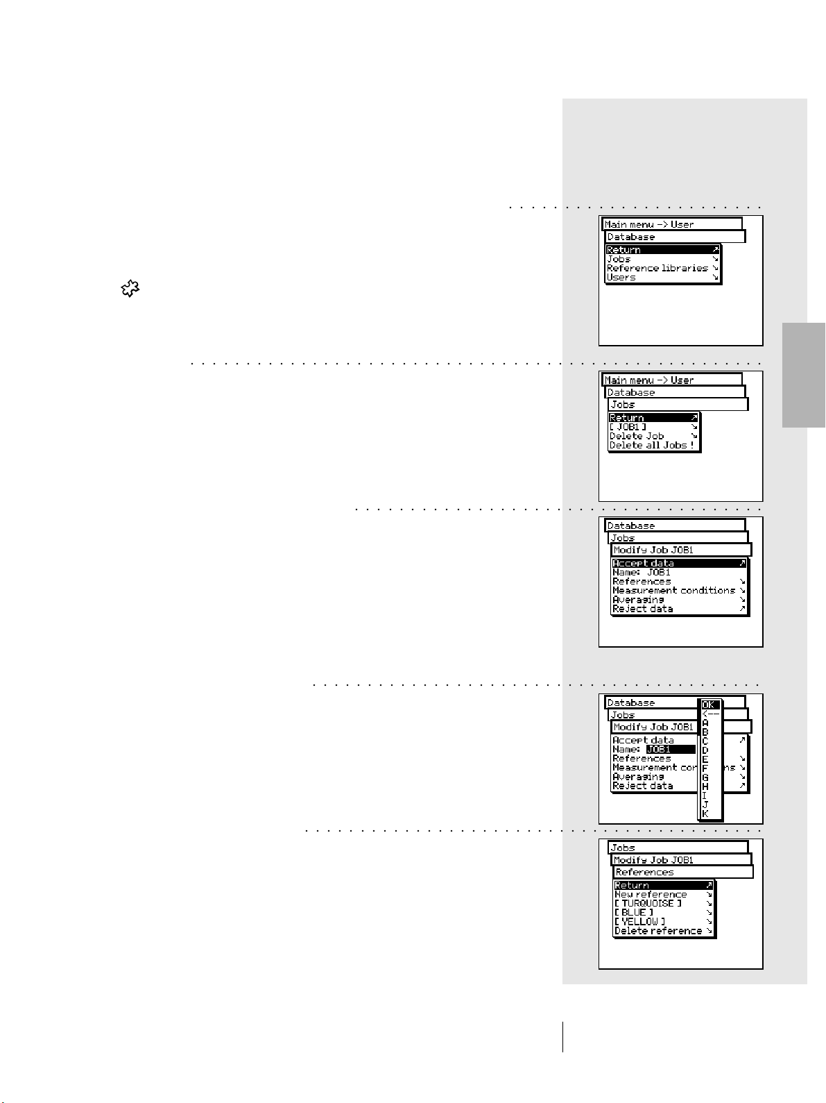
2.5 Database Management and Maintenance
A very important feature of SpectroEye is the possibility to
collect data inside the instrument for long term storage. From
the Database menu select:
• Jobs Collection of processed jobs including
customer and job specific data
• Reference libraries Collection of often needed references
apart from the customer jobs
• Users Collection of different user settings.
○○○○○○○○○○○○○○○○○○○○○○○
2.5.1 Jobs
If all the jobs have been stored inside the instrument, these can
be subsequently deleted or modified.
To do this, from main menu select
Database > Jobs
2.5.1.1 Modification of jobs data
From the Jobs menu, select the name of the job for which you
want to change the data.
The job specific data include:
- Name
- Reference
- Measurement conditions
- Averaging
To modify data, proceed as follows:
• Changing the job name
The job name may be changed, deleted or replaced with a
new name by simply selecting the Name: menu line.
○○○○○○○○○○○○○○○○○○○○○○○○○○○○○○○○○○○○○○○○○○○○○○○○○○○○
2
○○○○○○○○○○○○○○○○○○○○○○○○○○○○○○○○○○○○○
○○○○○○○○○○○○○○○○○○○○○○○○○○○○○○○○○○○○○○○○○
• Changing a reference
○○○○○○○○○○○○○○○○○○○○○○○○○○○○○○○○○○○○○○○○○○
From Modify Job menu, select the References menu line.
Here you can add new references, delete or modify already
existing references.
To modify a reference, select the Reference item.
The reference windows will appear.
Here you can change the desired items, as described in
section 2.4.2 Series Measurement.
SpectroEye™ 51
2 • Use
Page 52
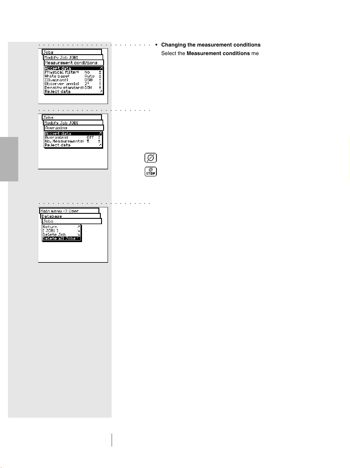
2
○○○○○○○○○○○○○○○○○○○○○○○○
○○○○○○○○○○○○○○○○○○○○○○○○
• Changing the measurement conditions
Select the Measurement conditions menu line and set up
the desired parameters:
- Physical filter
- White base
- Illuminant
- Observer angle
- Density standard
• Settings for averaging modification
Select the Averaging menu line. You can activate and
de-activate the automatic averaging feature, as well as
define the number of measurements to be used for the
averaging function.
If the averaging function is active, the toolbar buttons of the
measurement window will show the Averaging icon with
which you still have the possibility to change settings, and
the Stop Averaging icon, to immediately interrupt the
averaging function.
○○○○○○○○○○○○○○○○○○○○○○○○
2.5.1.2 Delete Jobs
From Database > Jobs menu, choose the Delete Job menu
item to select a given job to be deleted. To delete all the job‘s
data, select the Delete all Jobs menu item. The data will
be deleted only if you choose Yes to the delete confirmation
request.
SpectroEye™52
2 • Use
Page 53
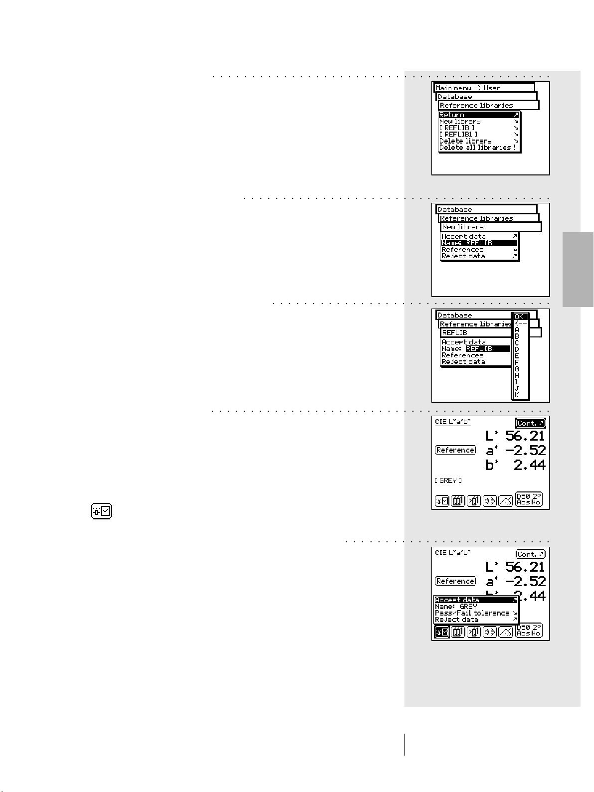
2.5.2 Reference libraries
A reference library is a collection of “personal” reference data
which come from different sources and may be saved as a
library: references can be obtained from the standard color
guides or they can be measured directly. This means that
a self defined selection will be available for your daily job.
○○○○○○○○○○○○○○○○○○○○○○○○○○○○○○○○○○○○○○○○○○○
2.5.2.1 Creating a new library
○○○○○○○○○○○○○○○○○○○○○○○○○○○○○○○○○○○○○○○
To create a new personal library, select the following from
the main menu:
Database > Reference libraries > New library
To create a library, proceed as follows:
○○○○○○○○○○○○○○○○○○○○○○○○○○○○○○○○○○○
• Enter the reference library name
SpectroEye automatically assigns a name to the new
reference library; however you can change it by selecting the
Name: menu item.
• Enter the reference
○○○○○○○○○○○○○○○○○○○○○○○○○○○○○○○○○○○○○○○○○○○
Select References > New reference menu; the references
window will appear. Check first whether the measurement
conditions meet your requirements.
Measure, the desired reference. As soon as the desired
measurement value is shown on the display, the reference
name automatically assigned by SpectroEye will appear,
and the toolbar buttons will include the Reference
parameters icon.
Select this icon to change the name of the color and to
define the tolerances for subsequent pass/fail evaluation.
2
○○○○○○○○○○○○○○○○○○○○○○○○○○
Change the name deleting that pre-assigned to the
Name: menu item and entering a new reference name.
To define the tolerances for these references select the
Pass/Fail tolerance menu item.
You can define both the density and colorimetry tolerances
for a subsequent evaluation. Confirm your settings using
Accept data.
SpectroEye™ 53
2 • Use
Page 54
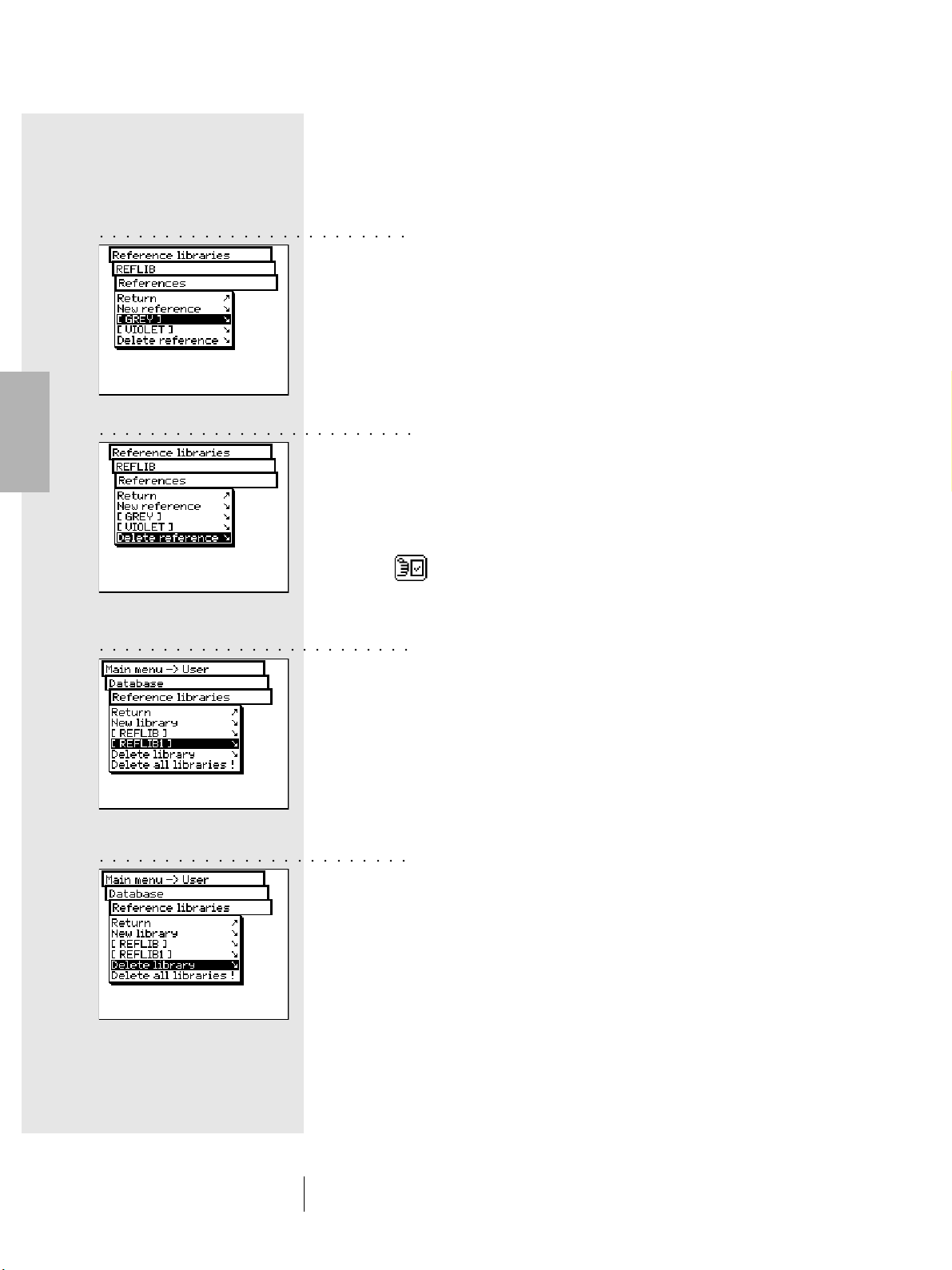
○○○○○○○○○○○○○○○○○○○○○○○○
Leave the references window using Continue. The new
reference will be inserted in the References menu and
you will be prompted to define a new project using New
reference. Repeat the described procedure for all
references.
• Subsequent management and cancellation of references
After the insertion of the last reference you will see, in the
References menu, a list containing all the reference names.
If, during the definition of a reference, you forget to specify
the tolerance values, you want to repeat the measurement
or further change the names, select the menu line
corresponding to the reference. The references window
will be displayed, where you carry out changes, as described
above.
2
○○○○○○○○○○○○○○○○○○○○○○○○○
○○○○○○○○○○○○○○○○○○○○○○○○○
○○○○○○○○○○○○○○○○○○○○○○○○
To delete a reference from the instrument memory, select
the Delete reference line from References menu, then
select the name of the reference you want to delete and
confirm with Ye s .
A subsequent management and cancellation of references
may also be performed inside the measurement window.
Through the Modify reference icon you reach the reference
window where you can carry out the desired changes.
2.5.2.2 Managing an existing library
From main menu select Database > Reference libraries.
Select from the list the desired library, than select the name
of the reference library to be modified using the Name: menu
item, or use References menu item to display the reference
data currently stored. Here you can process, add or delete
references, as described above.
2.5.2.3 Deleting a reference library
To select and delete a given library, select from Database >
Reference libraries menu, the Delete library menu item.
To delete all the libraries select the Delete all libraries menu
item. The data will be deleted only if you choose Ye s to the
confirmation request.
SpectroEye™54
2 • Use
Page 55
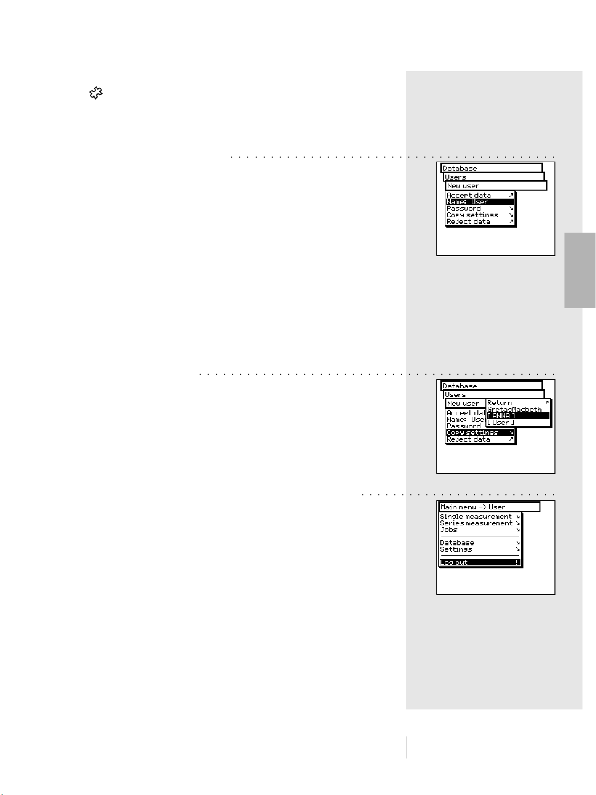
2.5.3 Users
With the Multi-user function package you will have the ability
to configure your SpectroEye for different users or user groups.
You may create new users inside the database, delete or edit
the user names and passwords.
2.5.3.1 Creating new users
○○○○○○○○○○○○○○○○○○○○○○○○○○○○○○○○○○○○○○○○○
From main menu, select the following item
Database > Users > New user
The software automatically assigns a user name. First
select the Name: menu item to delete the name automatically
assigned, and define a new unique name for the user.
Now define the password with which the new user will be
recognised in the future, by selecting Password > New
password menu item. If the user settings are not protected
by a password, this operation may be skipped.
Each user may automatically define its own settings in the
Settings > User defined menu. The available basic settings
can be used as a base for this definition. To get the settings
select the Copy settings menu item.
You may choose the following options (explained in the
following examples):
○○○○○○○○○○○○○○○○○○○○○○○○○○○○○○○○○○○○○○○○○○○○○
• GretagMacbeth Standard setting defined when the
SpectroEye is delivered.
• User x Setting related to an already
existing user.
2
Choose one of the above options and leave the New user
menu using Accept data.
If you have already stored one or more users, when you leave
the user database, the Log out item will appear on the main
menu. Select this menu item so that the system can recognise
you as a defined user.
Your setting will be loaded, however you will have the ability
to change it later on.
○○○○○○○○○○○○○○○○○○○○○○○○○
SpectroEye™ 55
2 • Use
Page 56
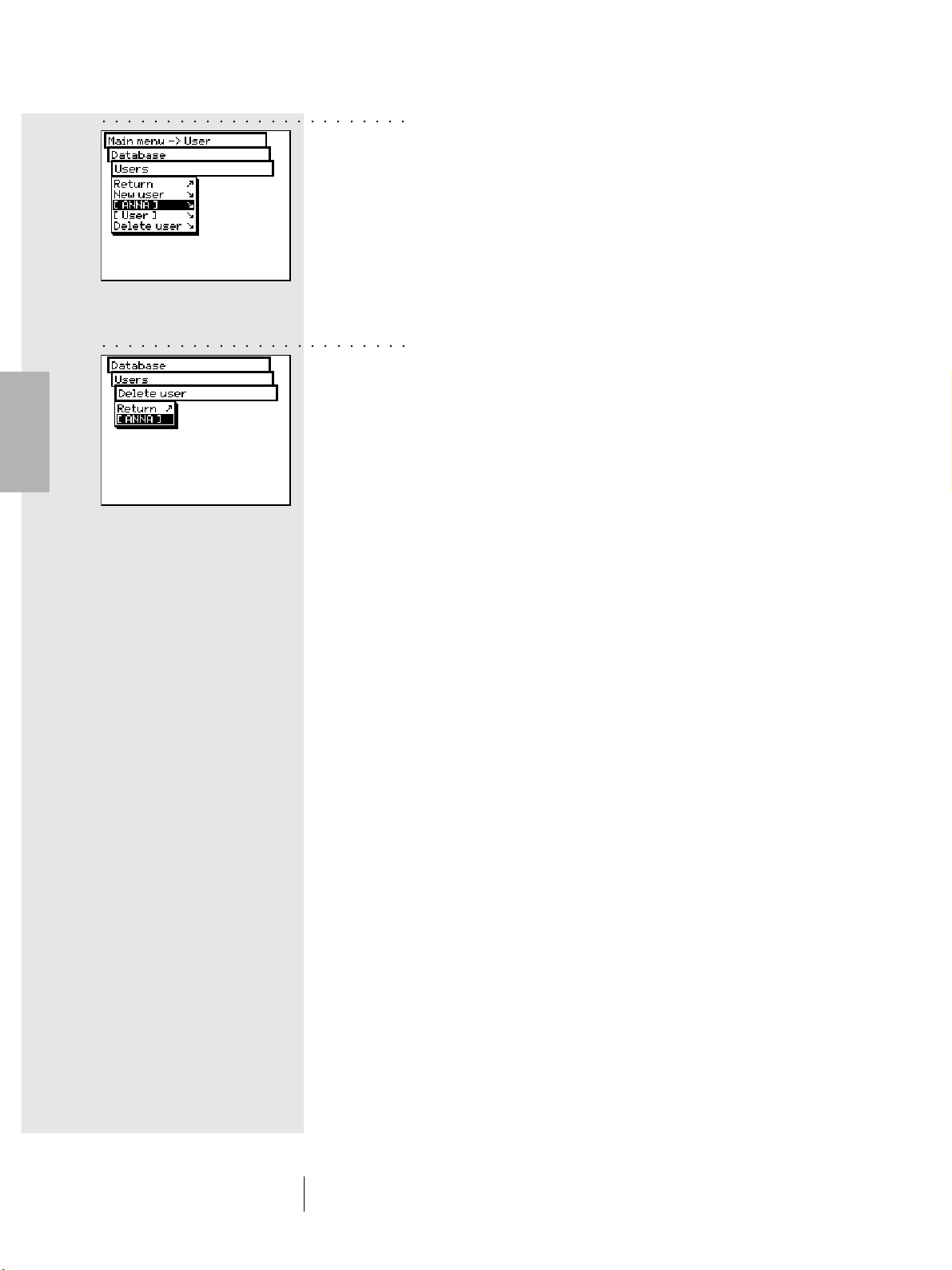
○○○○○○○○○○○○○○○○○○○○○○○○
2.5.3.2 Modify user
In order to modify data such as name, password or settings and
save them to a given user, first select the Database > Users
item from main menu, then select the user name from the list.
If the selected user has a password assigned, you will be
prompted to enter this password prior to making changes,
as described above.
2
○○○○○○○○○○○○○○○○○○○○○○○○
2.5.3.3 Delete user
To delete a user select the Database > User > Delete user
item from the main menu. The display will show all the users
not currently active. If you select a user and reply with Yes
to the confirmation question, the user will be deleted.
SpectroEye™56
2 • Use
Page 57
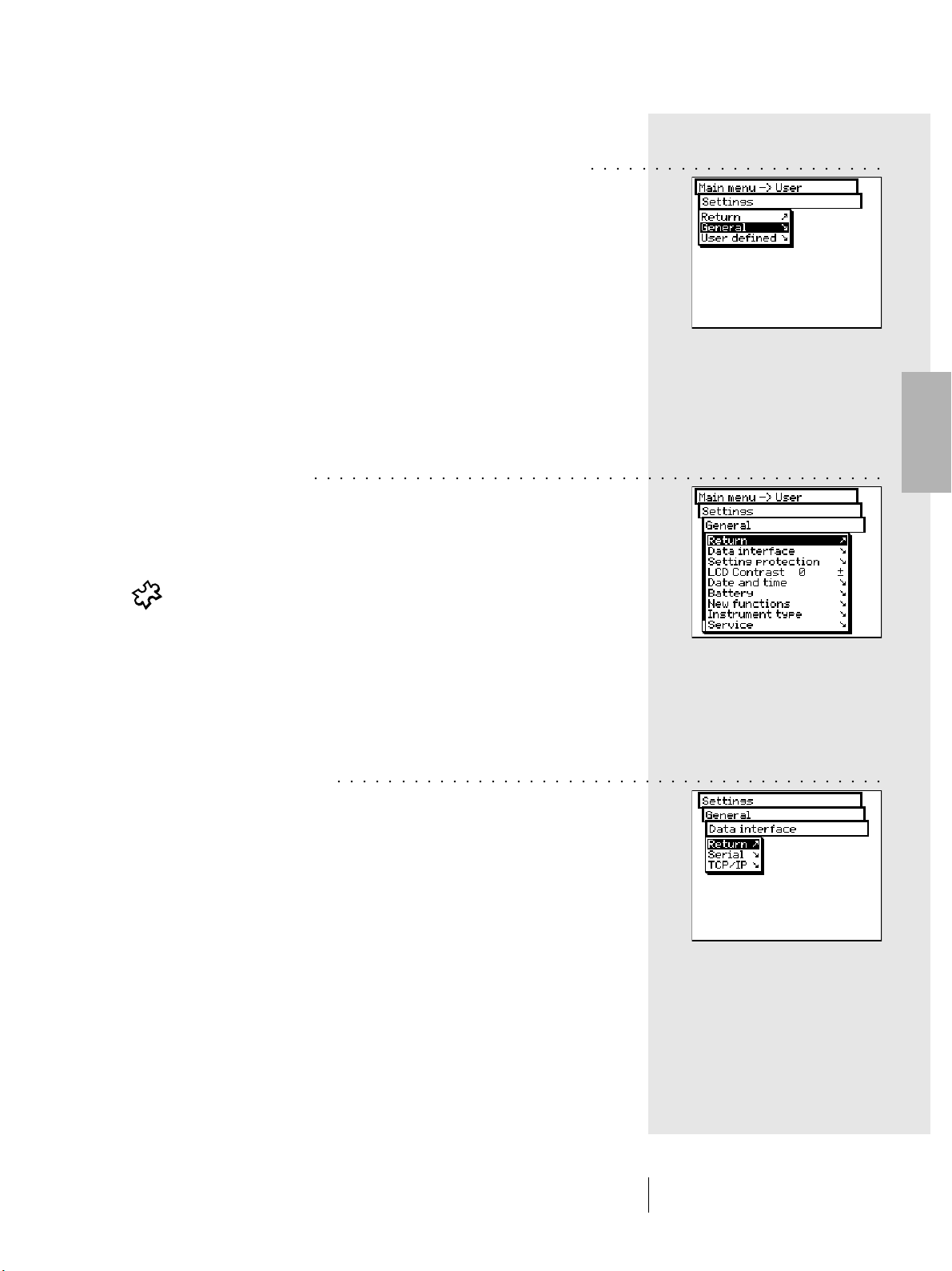
2.6 Settings
When working with the SpectroEye, modification of some basic
settings are rarely done or never need to be performed. Many
of these default settings directly influence measured results, so
these settings must be reviewed immediately after deactivating
the transport protection!
The basic settings can be found in the main menu under the
Settings option. These are subdivided into General and User
defined settings. General settings are global i.e. even if the
SpectroEye will be configured for several users, these settings
will apply to all. These are maintained until they are explicitly
modified. User defined settings refer to specific applications.
If the SpectroEye is subsequently configured for various users,
these can be independently configured for each user.
2.6.1 General settings
From the main menu, first select:
Settings > General
The following settings can be modified:
• Data interface
• Setting protection
• LCD contrast
• Date and time
• Battery
• New functions
• Instrument type
• Service
• Transport protection
○○○○○○○○○○○○○○○○○○○○○○○
○○○○○○○○○○○○○○○○○○○○○○○○○○○○○○○○○○○○○○○○○○○○○
2
2.6.1.1 Data interface
○○○○○○○○○○○○○○○○○○○○○○○○○○○○○○○○○○○○○○○○○○○
In order to correctly make the serial connection to the printer,
a computer, or to the Ethernet connection of the computer or
network, the interface parameters must be correctly configured.
The following is a description of the variations offered by the
Menu options:
Settings > General > Data interface
SpectroEye™ 57
2 • Use
Page 58
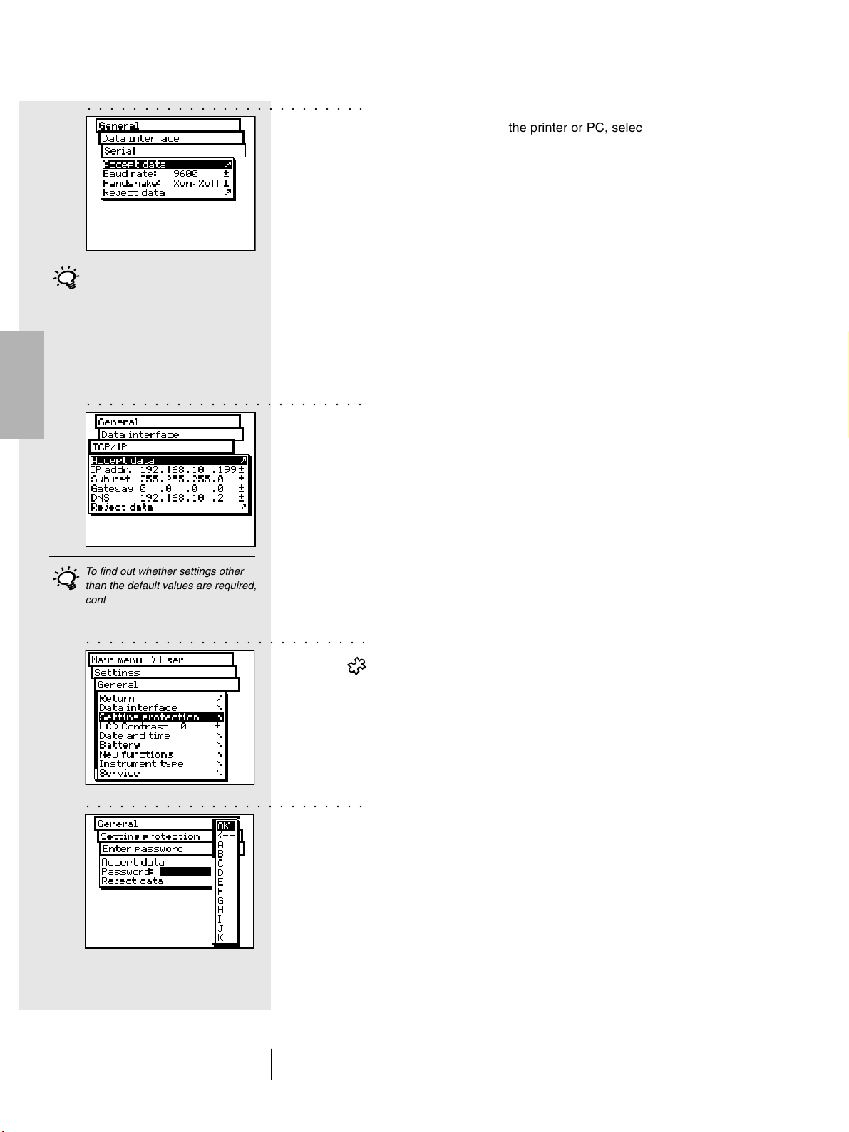
○○○○○○○○○○○○○○○○○○○○○○○○○
These settings must match those
of the connected device.
Please check the corresponding
instructions in the manual provided
by the device or software supplier.
The default settings are: Baud rate
= 9600 and Handshake = Xon/Xoff.
• To define the parameters for serial transmission between
the SpectroEye and the printer or PC, select the Serial option
and proceed as follows:
1. First set the correct transmission speed using the
Baud rate option.
2. Then under Handshake, select
- No
- Xon/Xoff
- Hardware
3. Save settings with Accept data.
2
○○○○○○○○○○○○○○○○○○○○○○○○○
To find out whether settings other
than the default values are required,
contact your system administrator.
○○○○○○○○○○○○○○○○○○○○○○○○○
○○○○○○○○○○○○○○○○○○○○○○○○○
• To connect the SpectroEye through an Ethernet interface
to the Internet or a company Intranet, select the TCP/IP
option and configure it as follows:
1. Set the sequence of correct addresses for:
- IP addr.
- Sub net
- Gateway
- DNS
2. Save settings using Accept data.
2.6.1.2 Setting protection
This menu item is available only if you have purchased the
Setting protection function package.
The following settings can be password protected against
unauthorised changes:
• Settings inside the Database > Users menu
• Settings inside the Settings menu
To enter a password, select the following from the main menu:
Settings > General > Setting protection >
New password
In the Password: menu item, indicate your password and
confirm with Accept data.
If a password was defined, when you try to access this menu,
you will be prompted to enter this password. Only when you
enter the password can you proceed with the setting phase.
SpectroEye™58
2 • Use
Page 59
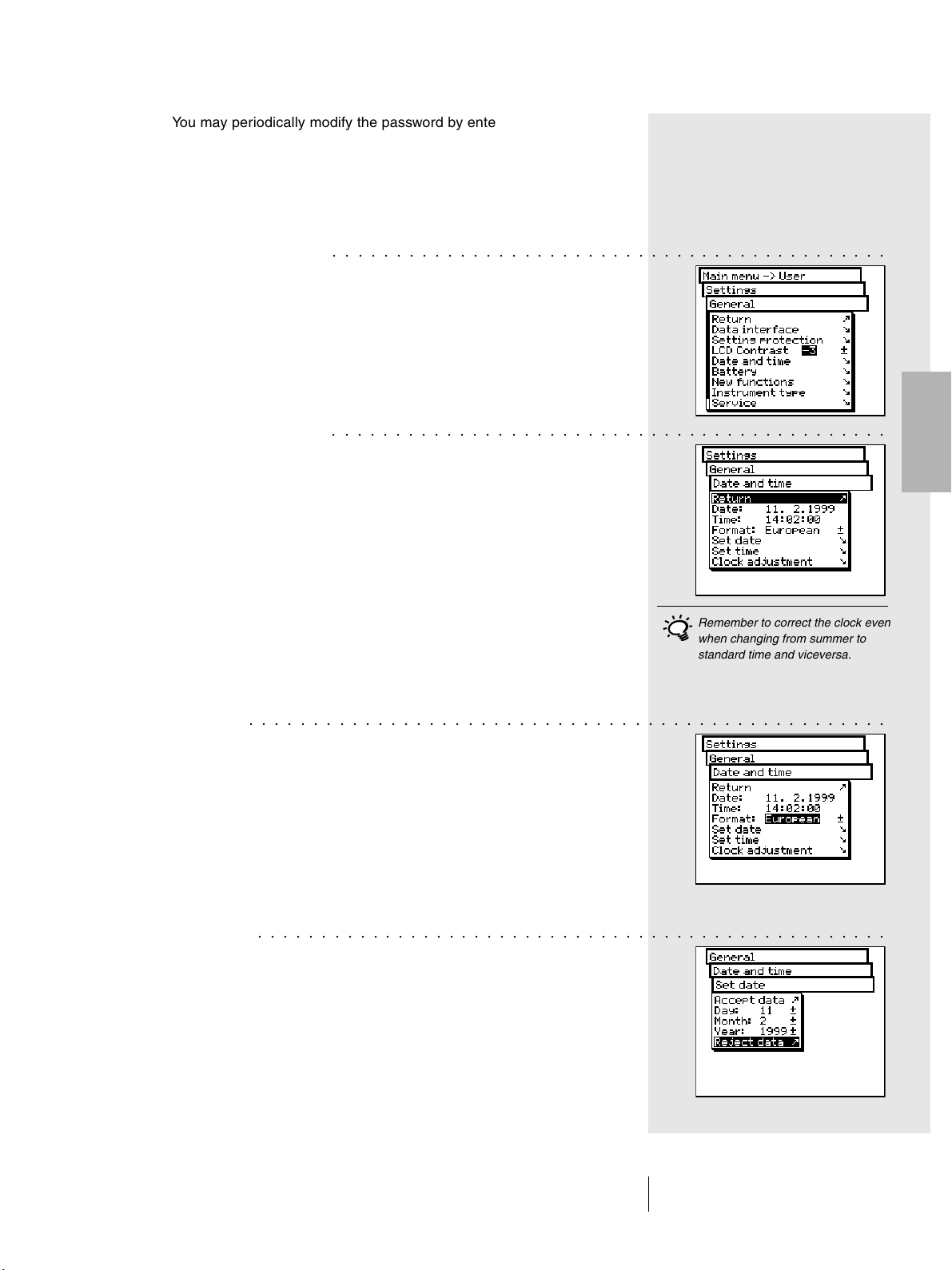
You may periodically modify the password by entering a
new password in the New password item, from the Setting
protection menu.
To remove a password protection, select the Delete password
item, from the Setting protection menu.
2.6.1.3 LCD contrast
○○○○○○○○○○○○○○○○○○○○○○○○○○○○○○○○○○○○○○○○○○○○
To adjust the LCD contrast to ambient lighting conditions,
from the main menu, select:
Settings > General > LCD contrast
To get the best contrast, select one of the values within the
scale. The change is immediately visible on the LCD.
2.6.1.4 Date and time
○○○○○○○○○○○○○○○○○○○○○○○○○○○○○○○○○○○○○○○○○○○○
To automatically integrate the measurement results with
the correct date and time, the SpectroEye is equipped with
a clock/calendar. Its accuracy should be checked regularly,
by selecting:
Settings > General > Date and time
The current date and time are displayed. If incorrect,
they can be modified in this menu:
• Format
○○○○○○○○○○○○○○○○○○○○○○○○○○○○○○○○○○○○○○○○○○○○○○○○○○
This command sets the display format for the date. Choose
between American or European format. American format
is month/day/year, where as European is day.month.year.
2
Remember to correct the clock even
when changing from summer to
standard time and viceversa.
• Set date
○○○○○○○○○○○○○○○○○○○○○○○○○○○○○○○○○○○○○○○○○○○○○○○○○○
Select the Set date menu option. Correct the settings of:
- Day
- Month
- Year
Save the new date with Accept data.
SpectroEye™ 59
2 • Use
Page 60
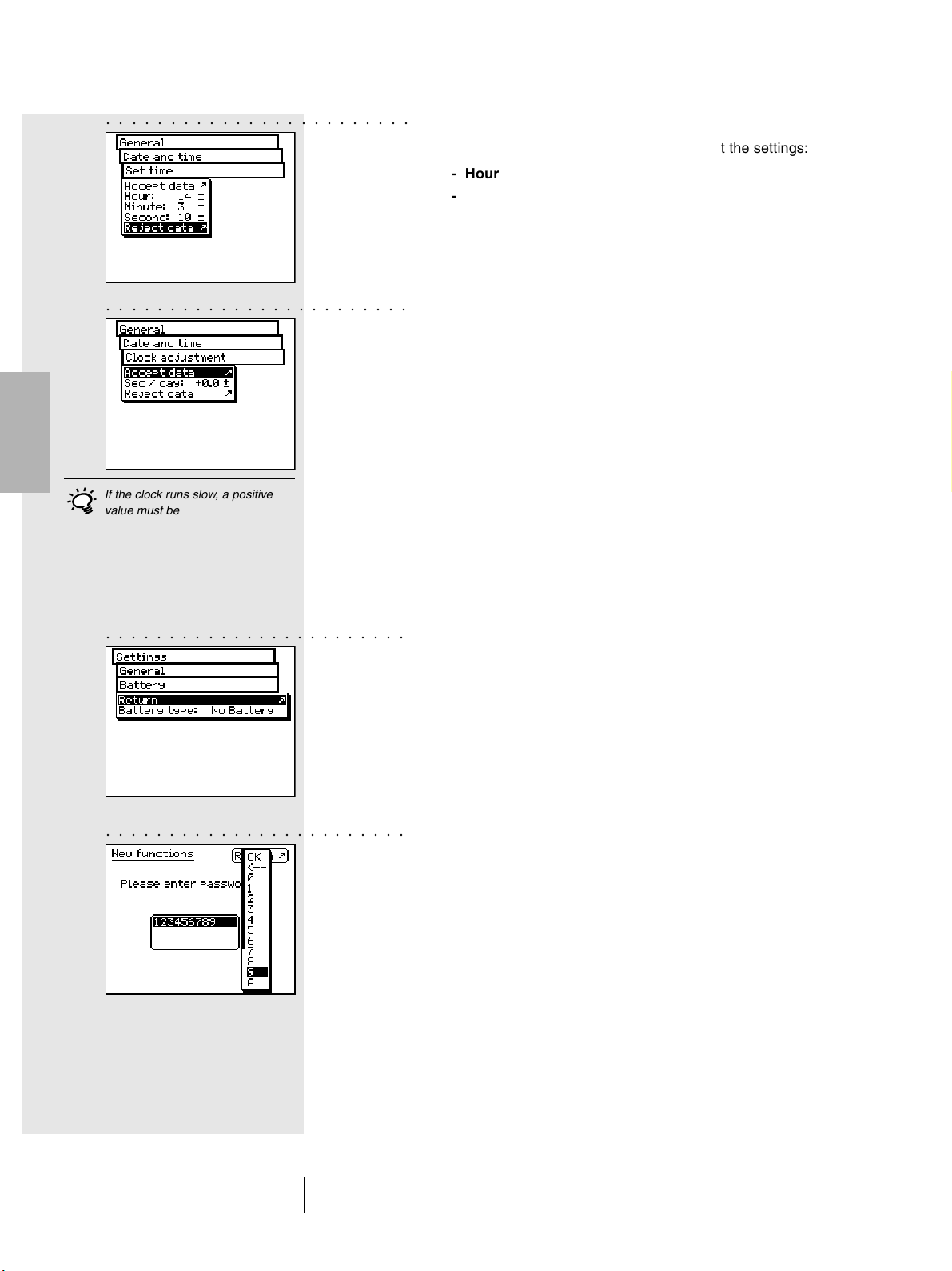
○○○○○○○○○○○○○○○○○○○○○○○○
• Set time
Now select Set time menu option. Correct the settings:
- Hour
- Minute
- Second
Save the new time with Accept data.
2
○○○○○○○○○○○○○○○○○○○○○○○○
If the clock runs slow, a positive
value must be entered (to speed
it up), whereas if it runs fast, this
value must be negative (to slow
it down).
○○○○○○○○○○○○○○○○○○○○○○○○
• Clock adjustment
The clock built into the SpectroEye may be running either
slightly fast or slightly slow. If the time on print-outs
is wrong, the clock can either be reset as described
previously, or its long term speed can be adjusted.
Proceed as described in the following example:
If after four weeks, you find that the SpectroEye clock
is four minutes slow.
1. Calculate the correction factor:
in 28 days, the clock lost 240 seconds, equal to
8.6 seconds per day.
2. Select Clock adjustment from the menu.
3. Select Sec/day and enter the correction factor +8.6.
4. Save the correction with Accept data.
2.6.1.5 Battery
From main menu, select the following item
Settings > General > Battery
to detect, which type of battery is being used.
○○○○○○○○○○○○○○○○○○○○○○○○
SpectroEye™60
2 • Use
2.6.1.6 New functions
The available functions of your SpectroEye may be configured
exactly according to your needs. The functions which you did
not purchase initially may be added by inputting a special code.
When you request a new function from your dealer, you will
receive a code allowing you to include the corresponding
measurement function.
To activate one or more functions, select the following
item from the main menu
Settings > General > New functions
At this point you will be requested to enter the special code.
Once the code has been specified, the new function will
be available.
Page 61
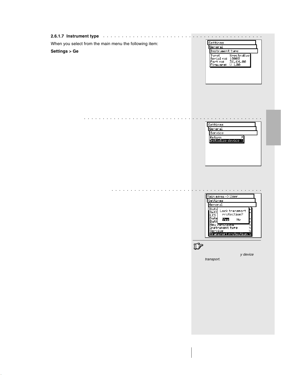
2.6.1.7 Instrument type
○○○○○○○○○○○○○○○○○○○○○○○○○○○○○○○○○○○○○○○○○○○
When you select from the main menu the following item:
Settings > General > Instrument type
the display will show all the information needed to identify
your instrument:
• Type
• Serial No
• Part No
• Firmware
These data are needed when you request service support,
either directly or via internet.
2.6.1.8 Service
○○○○○○○○○○○○○○○○○○○○○○○○○○○○○○○○○○○○○○○○○○○○○○○○
In the case of a particular problem, your service centre will
request you to perform the instrument initialization.
To do this, select the Initialize device item from the Settings >
General > Service menu.
During the device initialization, the software will be restarted
and the interface will be reset. In this phase only the current
measurement data are deleted, while the series or jobs data
will not be affected. During the first measurement cancellation
phase, the filter wheel will also be re-inizialized.
2.6.1.9 Transport protection
○○○○○○○○○○○○○○○○○○○○○○○○○○○○○○○○○○○○○○○○
Before packing and sending your SpectroEye or transporting
on long travels, it is advisable to activate the transport
protection feature. This will help to avoid damage to the
measurement head due to accidental bumps.
To activate the transport protection, select the following from
the main menu:
Settings > General > Transport protection > Lock transport
protection
and confirm with Yes.
To remove the transport protection, simply enter the
number 259.
2
To avoid damage you are requested
to activate the electronic transport
protection before every device
transport.
SpectroEye™ 61
2 • Use
Page 62
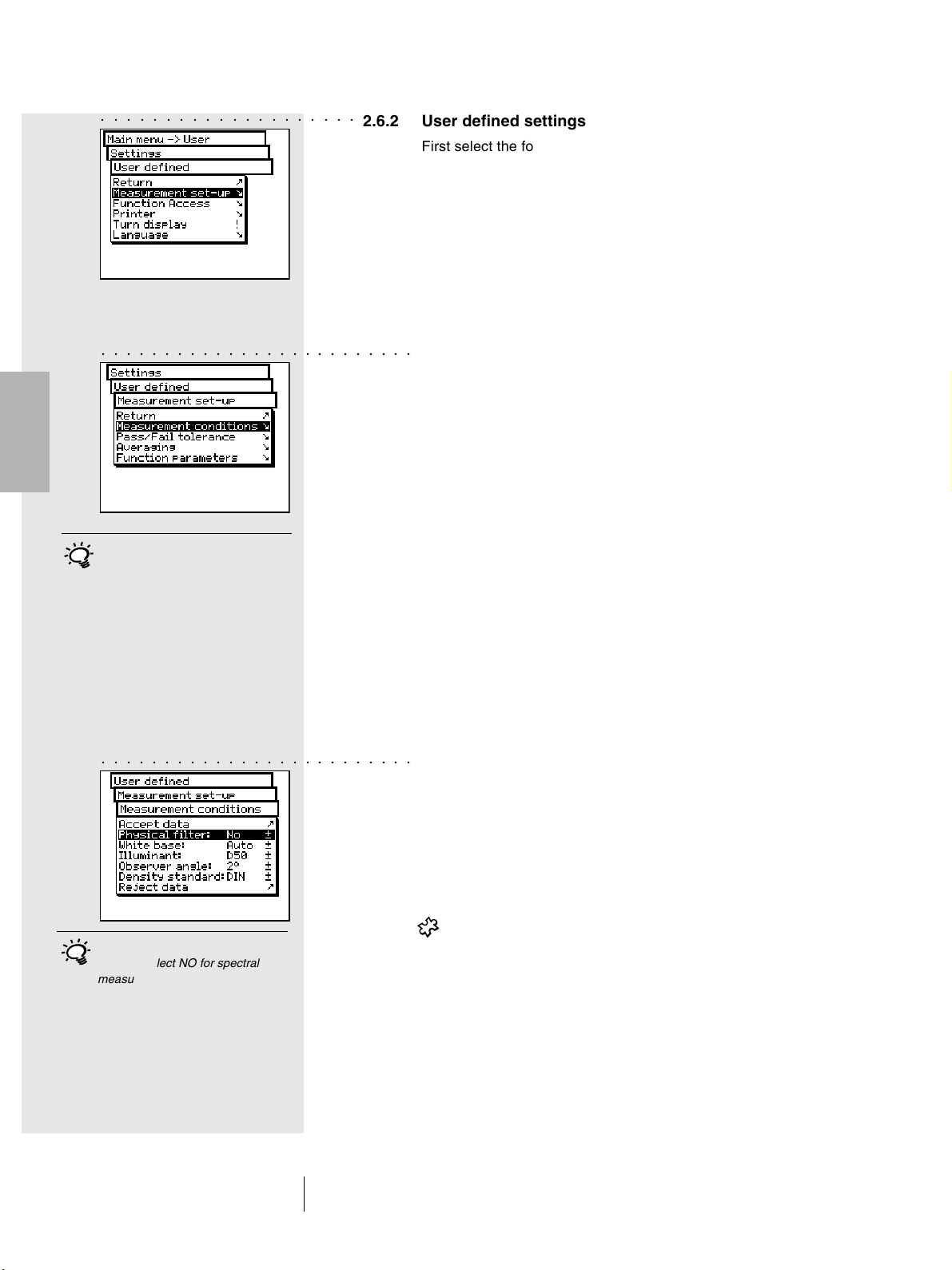
○○○○○○○○○○○○○○○○○○○○
2.6.2 User defined settings
First select the following from the main menu
Settings > User defined
Here you can define the following settings:
• Measurement set-up
• Function Access
• Printer
• Turn display
• Language
2
○○○○○○○○○○○○○○○○○○○○○○○○○
Here you should select the most
frequently used settings in normal
operation. In this way it is possible
to guarantee a consistency to the
color measurement, which should
only be modified occasionally to
meet the application requirements.
○○○○○○○○○○○○○○○○○○○○○○○○○
2.6.2.1 Measurement set-up
Settings of Measurement set-up menu are considered the
default ones. They are always taken as basic settings when
you are working with a Single measurement or when you create
a Series measurement or Jobs.
To define these basic settings, starting from the main menu
you must select
Settings > User defined > Measurement set-up
and then:
• Measurement conditions
All settings of the Measurement conditions menu should
be made with great care as they affect the measurement
results. They can be checked on the symbol bar of
the measurement window and can be changed to meet
the application requirements, at any time.
The measurement conditions include:
- Physical filter
Determine if the measurement must be performed using
a physical filter.
If you don‘t know which filter must
be used select NO for spectral
measurements and POL for
densitometric measurements.
The following filter settings are available
-No -> without filter
- Pol -> polarisation filter
- D65 -> Average North Sky daylight
- UVCut -> UV suppression
SpectroEye™62
2 • Use
Page 63
- White base
For a correct spectral or density measurement,
the corresponding white base must be defined.
The following settings are available
- Auto -> automatic selection
- Pap -> paper white
- Abs -> absolute white
If you select Pap, as white base, all subsequent
measurements will refer exclusively to the printed ink layer,
while the paper color effect will not be included. To obtain
the basic base reference you should always measure
the paper used.
If you select Abs, besides the printed ink layer, the
measurement will also include the paper effect.
Here the integrated white reference will be used as
the white base.
If you select Auto, SpectroEye will automatically use the
white base usually adopted for the selected function.
For densitometric functions, this is the white base of paper,
while for spectrophotometric functions it is the absolute
white base.
In practice the densitometric
analyses are based on paper
(Pap setting) while the spectrophotometric ones are based on
the integrated white reference
(Abs setting). It is advisable to
select the Auto setting and
change it only in special cases.
2
- Illuminant
To calculate the special color values, select the desired
normalised illuminant.
The most commonly used normalised illuminants are
already available:
A, C, D65, D50, F2, F7, F11
The normalised illuminants of D and F series must be
set-up using the Dxx and Fxx menu items. When you
perform this selection, an additional menu line appears,
where you can select the desired color temperature.
Here the following illuminants are available:
Fxx: F1 to F12
Dxx: D30 to D300
- Observer angle
When analysing the colorimetric values, the calculation
and consequently the result depend on the definition of
the observer angle.
In this menu line you must select the observer angle,
normally between 2° and 10°.
Usually the normalised illuminant
for the Graphic Arts industry used
in the USA is D50 while in Europe
it is D65.
You can freely select one of the two
settings. It is extremely important
that for chromatic comparison the
selected setting is always kept
constant.
SpectroEye™ 63
2 • Use
Page 64
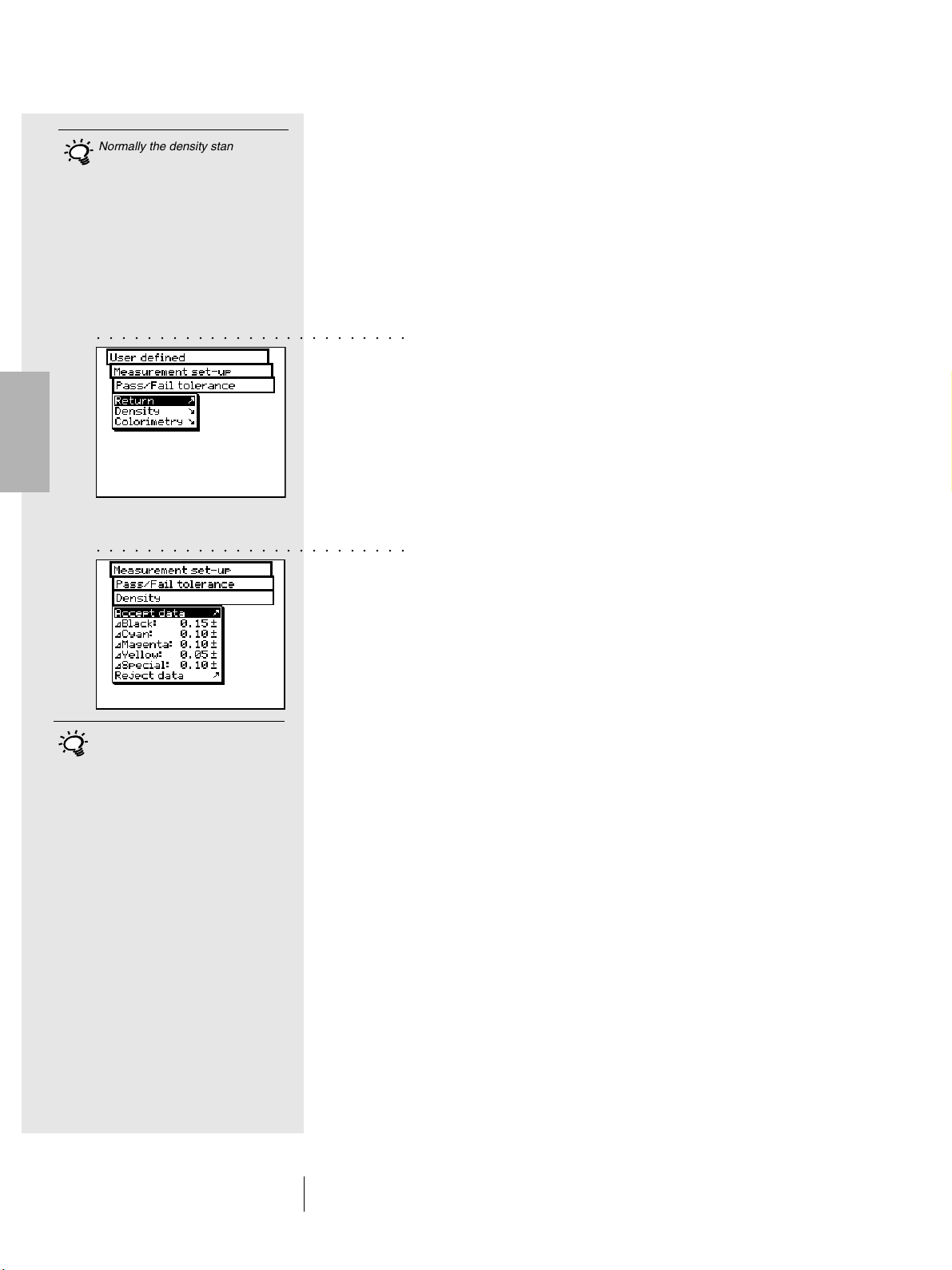
Normally the density standard used
in the USA is ANSI T while in
Europe it is DIN. As a guide line it
is advisable to select the settings
corresponding to the set of physical
filters available on the densitometer.
- Density standard
If you wish to use the SpectroEye spectrophotometer
also as a densitometer, you must define which density
standard to operate with.
In this menu line select either:
DIN, DIN NB, ANSI A, ANSI T, SPI
Save your settings in Measurement conditions menu using
Accept data and proceed with:
2
○○○○○○○○○○○○○○○○○○○○○○○○○
○○○○○○○○○○○○○○○○○○○○○○○○○
The tolerances set-up in this menu
must be considered only as a first
recommendation. It is advisable
to tune tolerance limits based
on customer needs and product
requirements.
• Pass/Fail tolerance
When you work with Series measurements or Jobs,
immediately after the reference and sample measurement,
you obtain an evaluation in terms of pass/fail.
The measured values are included in (Pass) or excluded from
(Fail) based on the tolerance values defined in this menu.
The tolerances are defined separately for densitometric and
spectral measurements as follows:
Starting from the Measurement set-up menu, select
Pass/Fail tolerance > Density
Enter the sequence of tolerances corresponding to the
maximum densities of the process colors. The tolerance
values indicate how much the solid density value of a
measured sample can shift from the solid density of the
reference.
Example:
The reference for cyan has been measured with a solid
density of 1.55. The tolerance value was set-up to +/- 0.10.
All the measured samples are within the density range
of 1.45 and 1.65 i.e. within the allowed tolerance. Therefore,
in the measurement window Pass will be displayed. If the
solid density is higher or lower than such limits, Fail will
be displayed.
SpectroEye™64
2 • Use
Page 65
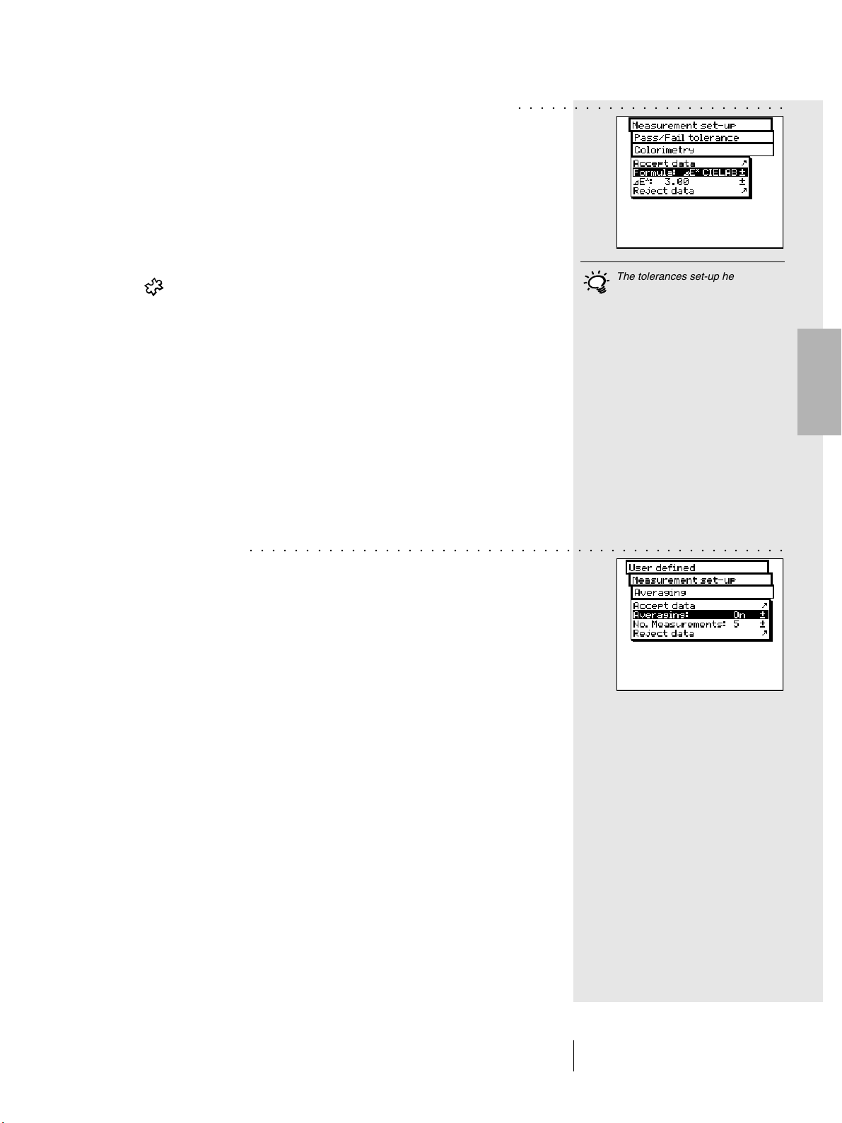
Next, starting from the Measurement set-up menu, select
Pass/Fail tolerance > Colorimetry
In the Formula: menu line select the formula you want to use
to define the tolerance.
The following formulas and tolerance settings are available:
Supplied with the base - L*a*b*
instrument - E* CIELAB
Options - E CMC, E FMCII, E*94
- E* CIELUV
-E mg
- E Hunter Lab
As soon as you have chosen one of the above formula,
the corresponding parameters are displayed in one or more
menu lines. When the data entry procedure is completed,
save the tolerance values using Accept data.
All the subsequent Pass/Fail evaluations will refer to this
formula and to the tolerances defined here. The Pass/Fail
evaluation is displayed only if the corresponding
measurement function has been selected.
○○○○○○○○○○○○○○○○○○○○○○○○
The tolerances set-up here must
be considered only as a first
recommendation. It is advisable
to tune tolerance limits based
on customer needs and product
requirements.
2
• Averaging
○○○○○○○○○○○○○○○○○○○○○○○○○○○○○○○○○○○○○○○○○○○○○○○○
For non-homogeneous samples and references SpectroEye
is able to calculate the average of different measurements.
Starting from the Measurement set-up menu, select
Averaging.
Here you can activate or de-activate automatic averaging,
as well as set-up the number of measurements to be taken
for each average. If the averaging function is activated, an
icon appears on the symbol bar of the measurement window,
which allows these settings to be changed.
SpectroEye™ 65
2 • Use
Page 66
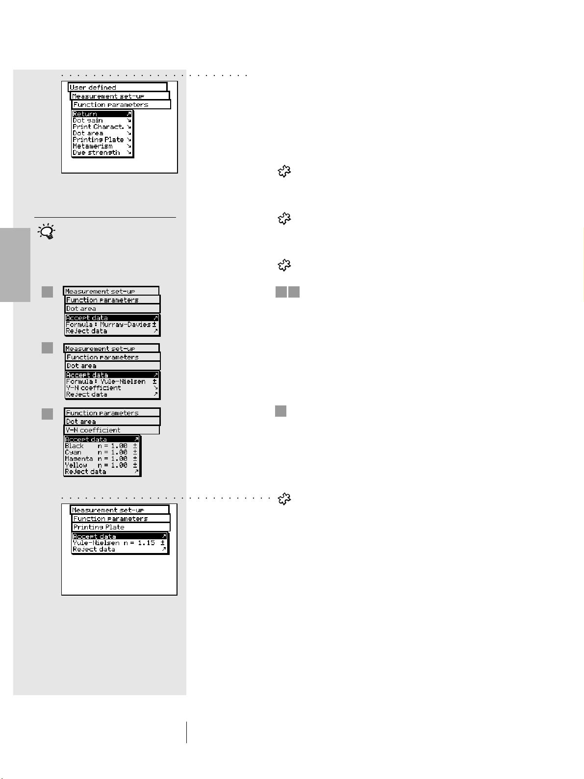
○○○○○○○○○○○○○○○○○○○○○○○○
• Function parameters
Some measurement functions are based on parameters
which must be adjusted to individual working conditions.
To modify these, starting from the Measurement set-up
menu, select Function parameters.
Enter each parameter used for the following functions:
- Dot gain
Enter the screen percentage value provided in the
color bar halftone fields for dot gain measurement.
2
Normally the Murray-Davis formula
is used. The Yule-Nielsen formula
should only be used in special
cases, i.e. to determine the physical
area coverage.
1
2
3
○○○○○○○○○○○○○○○○○○○○○○○○○○○
- Print characteristic
Set-up the halftone levels from which the print
characteristics must be created.
- Dot area
For dot area calculation you may use the
1
2
Murray-Davies and Yule-Nielsen formulas.
While for the Murray-Davies formula the degree
of light optical absorption is predefined, in the
Yule-Nielsen formula this can be adapted for
different conditions.
First, select the Formula: menu item, and choose
the formula to be used for calculation. If you choose
the Yule-Nielsen formula, another line appears
within the menu where you can set the
Y-N coefficient. Here the “n” values for black, cyan,
3
magenta and yellow are entered.
- Printing Plate
When measuring the printing plate, to determine
the physical dot area coverage of your printing
plate, set the Yule-Nielsen factor.
SpectroEye™66
2 • Use
Page 67
- Metamerism
By determining the metamerism index you define
the mutual color modification of two colors when
the illuminant changes. The first illuminant used is
that defined within the
Settings > User defined > Measurement set-up >
Measurement conditions > Illuminant
menu.
Enter the test illuminants for which the color changes
of the first illuminant must be determined.
You may define a maximum of three test illuminants.
- E CMC
In order to calculate the color difference using
CMC, you must enter the correction factors for
brightness (i) and chroma (c).
The recommended settings for the
printing industry are: l=2 and c=1.
- E*94
To calculate the color difference using to E*94
you must enter the correction factors for brightness
(kL), chroma (kC) and hue (kH).
- Dye strength
To determine the dye strength you must first choose
one of the available calculation methods:
at max K/S, xyz weight KS and Best Match E .
Next, access the Colorant menu item, enter the type
of ink for which you wish to determine the dye
strength. You may choose Transparent ink,
Opaque ink and Textile dye.
During the measurement, the symbol bar of the measurement
window shows the function parameter icon. After having selected
the corresponding measurement functions you can always change
all settings performed.
2
The recommended settings for the
printing industry are: kL=1, kC=1
and kH=1.
In general, any function is neither
cancelled nor inserted here, but rather
made available in the user area.
SpectroEye™ 67
2 • Use
Page 68
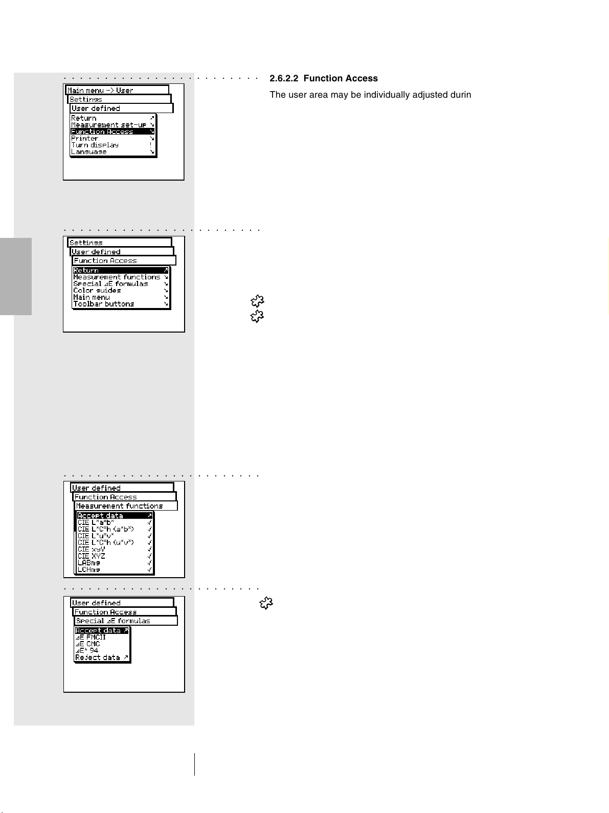
2
○○○○○○○○○○○○○○○○○○○○○○○○
○○○○○○○○○○○○○○○○○○○○○○○○
2.6.2.2 Function Access
The user area may be individually adjusted during the function
access, according to the specific user needs. For example,
if you want to use your SpectroEye as a simple density
measurement tool, connected to a printer, you will want to
de-activate all the spectrophotometric functions. This setting
may be performed separately for each user, so that every
operator has an optimised user area available for their own job.
To activate and/or de-activate the desired function, select
the following from the main menu:
Settings > User defined > Function Access
According to the working needs, it is possible to carry out
the following settings:
• Measurement functions
• Special E formulas
• Color guides
• Main menu
• Toolbar buttons
As soon as you select the menu lines, these are marked with
a “check symbol” and made available to the user. When you
select the marked menu lines, the “check symbol” is removed.
In this way, that function will not be available any more in the
user area.
○○○○○○○○○○○○○○○○○○○○○○○○
○○○○○○○○○○○○○○○○○○○○○○○○
The setting options of each individual sector is explained
in detail in the following list:
• Measurement functions
In the Function Access menu, select the Measurement
functions menu item. This menu allows one to define
which measurement functions can be selected within the
measurement window using the Measurement function
icon. The selected settings becomes active using
Accept data.
• Special E formulas
In the Function Access menu, select the Special E
formulas menu item. Usually, not all the formulas available
will be used. Through the E Form ula icon you may
determine which special E-formula(s) must be made
available inside the measurement window. The selected
settings become active using Accept data.
SpectroEye™68
2 • Use
Page 69
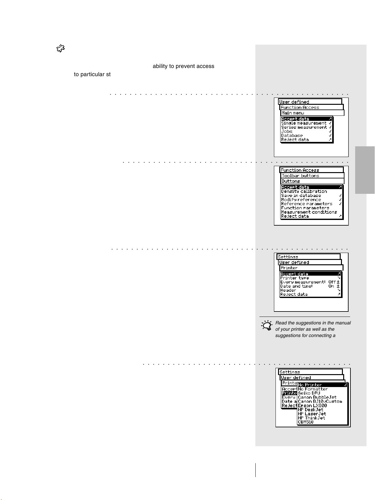
• Color guides
In the Function Access menu, select the Color guides
item menu. Here you have the ability to prevent access
to particular standard color guides. The selected settings
becomes active using Accept data.
• Main menu
○○○○○○○○○○○○○○○○○○○○○○○○○○○○○○○○○○○○○○○○○○○○○○○○
In the Function Access menu, select the Main Menu item.
Here you have the ability to prevent access to particular
areas of the main menu. The selected settings becomes
active using Accept data.
• Toolbar buttons
○○○○○○○○○○○○○○○○○○○○○○○○○○○○○○○○○○○○○○○○○○○○○
In the Function Access menu, select the Toolbar buttons
> Buttons item.
Here you can decide which icons will be available in the
toolbar of the measurement window. The selected icons
will become active using Accept data.
Selecting the Balloon help menu item in the Toolbar buttons
menu, you can decide if the measurement window icons will
have to be explained by means of an on-line help.
2.6.2.3 Printer
○○○○○○○○○○○○○○○○○○○○○○○○○○○○○○○○○○○○○○○○○○○○○○○○
Measurement results can be sent directly to a printer, without
the need of a computer. In such cases the printer is connected
directly to the SpectroEye through the serial interface port.
To obtain a correct print-out, it is necessary to give the
SpectroEye specifics about the printer to be used.
2
Read the suggestions in the manual
of your printer as well as the
suggestions for connecting a printer
to SpectroEye from chapter 1.2.3.5
to chapter 1.2.3.6.
From the main menu, select
○○○○○○○○○○○○○○○○○○○○○○○○○○○○○○○○○○○○○○○○○○
Settings > User defined > Printer
and proceed as follows
1. First, select the Printer type option and then the model
of printer to use.
Available printers:
• No printer
• No formatter
• Seiko DPU
• Canon BubbleJet
SpectroEye™ 69
2 • Use
Page 70
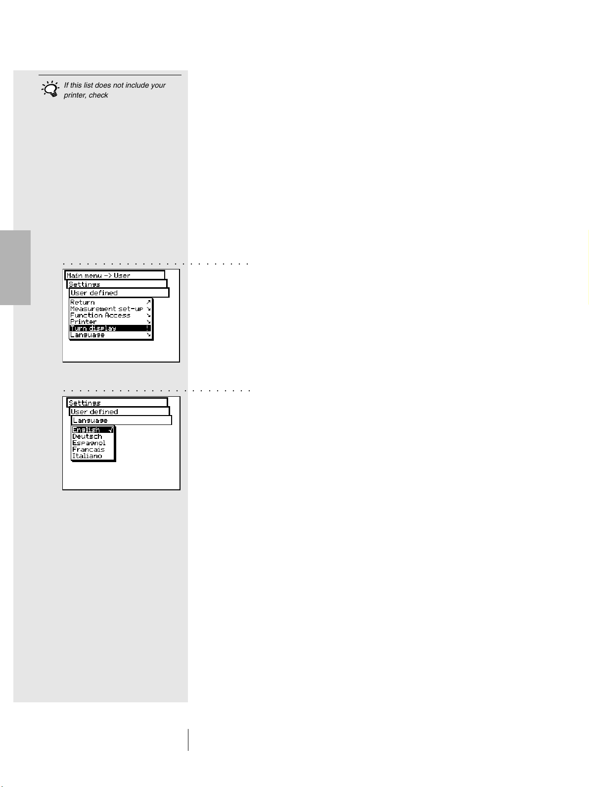
If this list does not include your
printer, check the printer manual to
see if this is compatible with one of
the listed models. Otherwise select
the No Formatter option.
• Canon BJ10vCustom
• EPSON LX800
• HP DeskJet
• HP LaserJet
• HP ThinkJet
• CBM510
2. If you require the date and time to be entered automatically
with the print-outs, select Date and time menu option and
set the displayed value to On.
3. The printer protocol heading can be defined by selecting
the Header menu item. Enter the text which is to appear
in the printer protocol; 5 lines are available.
4. Save settings using Accept data.
2
○○○○○○○○○○○○○○○○○○○○○○○○
○○○○○○○○○○○○○○○○○○○○○○○○
2.6.2.4 Turn display
The SpectroEye is designed to be used with one hand.
On delivery from the factory, it is set for use with the right hand.
So that left-handed people may also use the SpectroEye with
ease, the displayed data can be rotated.
From the main menu, select
Settings > User defined > Turn display
The display on the LCD is immediately rotated.
2.6.2.5 Language
The SpectroEye software is available in several languages.
To change the language, select the following from main menu:
Settings > User defined > Language
The display changes as soon as you select the requested
language.
If you press and hold down the measurement key for about
15 seconds, the program immediately selects the language
menu. In this way you can easily switch from an unknown
language to a known one.
SpectroEye™70
2 • Use
Page 71
3.1 Best Match
3.1.1 General 72
3.1.2 Configuring the Function 73
3.1.3 Performing the Measurement 73
3.1.4 Interpreting the Measurement Results 74
Set-up
Use
1
2
SpectroEye™ 71
3 • Functions
Functions
Appendix
3
4
Page 72
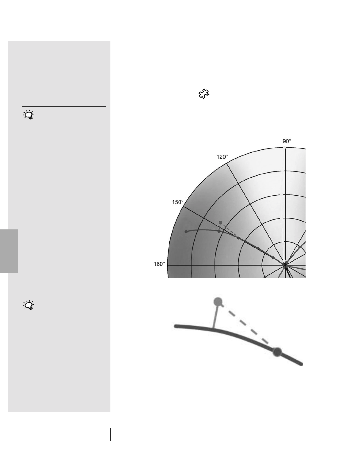
3. Functions
In this chapter we will take a detailed look at selected functions
which highlight the high standard of the SpectroEye unit.
3.1 Best Match
3
The SpectroEye Best Match
function allows you to quickly and
easily establish if a mixed color
matches a specified target color or
whether you will need to mix a new
batch. The deviation is calculated
on the basis of colormetric and
densitometric differences between
the reference and the sample colors.
The colormetric deviations are
provided as ∆E (color difference)
and the densitometric differences
as D (density difference).
The densitometric measurement
also helps when printing special
colors and checking screen colors
by indicating the required layer
thickness (in offset printing) and
concentration (in flexo and gravure
printing) with which a color must be
printed to achieve the most accurate
reproduction of the target color.
3.1.1 General
The illustration below shows the Best Match function with
the aid of the CIELAB color space using an example of two
different shades of green:
∆E Best Match
∆E akt
You can use the Best Match
function when formulating
and mixing colors and to check
the color during printing. This
function detects the slightest
deviations from the target
color immediately, saving you
time and money throughout
the print run.
Reference
∆E Best Match
Best Match Point
Sample
The curve describes the hue shift when changing the ink
thickness in relation to ink concentration. The length of the
line forming a perpendicular connection between the reference
point and the curve corresponds to the Best Match for the
nominal value.
SpectroEye™72
3 • Functions
Page 73
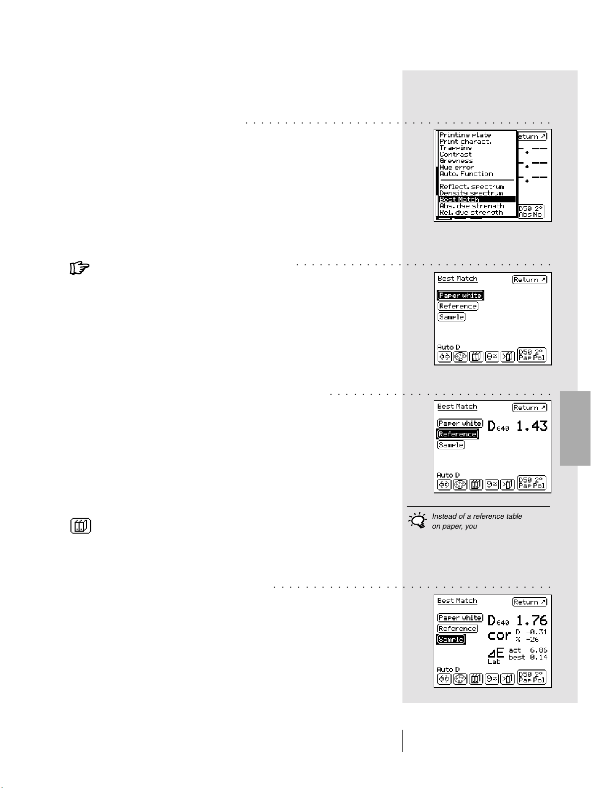
3.1.2 Configuring the Function
From the Main Menu, select Single Measurement.
Select the Measurement Function icon.
Select the Best Match function.
3.1.3 Performing the Measurement
Always measure Paper White first. To do this,
select Paper White, place the measurement
module on the point you want to measure and
press the measurement pad.
Now measure the Reference Color. To do this,
select Reference, place the measurement module
on the point you want to measure and perform
the measurement.
○○○○○○○○○○○○○○○○○○○○○○○○○○○○○○○○○○○○○○○
○○○○○○○○○○○○○○○○○○○○○○○○○○○○○○○○○
The displays shows the measured Density D with the
associated Wavelength. In this case, we use a shade
of green as the reference color. The density D is
measured at a wavelength of 640 nm and is 1.43.
To do this, select the icon Accept from Database and
select the desired color (for example, Pantone colors).
You are now ready to measure the color
○○○○○○○○○○○○○○○○○○○○○○○○○○○○○○○○○○○
you want to compare.
Choose a Sample.
Place the measurement module on the point you want
to measure and perform the measurement.
○○○○○○○○○○○○○○○○○○○○○○○○○○○○
3
Instead of a reference table
on paper, you can also copy
special color combinations from
the database.
SpectroEye™ 73
3 • Functions
Page 74
The maximum permitted Color
Difference ∆E is determined
for each print job. If the value
of∆E best is greater that the
specified ∆E, you cannot achieve
the desired color quality by
changing the density.
3.1.4 Interpreting the Measurement Results
Here we measure a second shade of green, for example, which
has as its Density D a value of 1.76 at 640 nm. Below this you
can see the recommended Correction cor needed to achieve
optimum results: in relation to the reference color you should
correct the Density D by -0.31/-26% in order to achieve the
closest possible match with the target color.
The color difference ∆E akt indicates how close the current
color is to the desired target color. In our example ∆E akt is 6.86.
If you implement the recommended changes to the density, you
can achieve a color difference of ∆E best as the Best Match
(optimum possible match). In our example ∆E best is 0.14.
3
For more information on printing,
please refer to Chapter 2.4.1.5
Printing the Measurement Values.
You can print this measurement result by selecting
the Print icon.
SpectroEye™74
3 • Functions
Page 75
4.1 Technical specification 77
4.2 Declaration of conformity 78
Set-up
1
Use
Functions
2
3
SpectroEye™ 75
4 • Appendix
Appendix
4
Page 76

SpectroEye™76
Page 77

4.1 Technical specifications
STANDARD OPTIONS
Measurement Colorimetry CIE L*a*b*, CIE L*C*h (a*b*), E* CIELAB
functions
Special color deviation formulas optional
Densitometry Density
Spectrum Reflection spectrum
Dye Strength optional
White- and Yellowness optional
Special functions optional
Color guides optional
Security optional
Measurement White base absolute, relative
conditions Illumination types D50, D65, A, C, D30…D300, F1…F12, User defined
Standard observers 2°, 10°
Density standards DIN 16536, DIN 16536 NB, ANSI Status A,
ANSI Status T, ISO Status I (SPI), User defined
Measurement Spectral analysis holographic diffraction grating
technology Spectral range 380nm to 730nm
Physical resolution 10nm (internal resolution: 3,3nm)
Measurement modes Reflection
Measurement geometry 45°/0° ring optic, DIN 5033
Measurement aperture 4.5mm
Light source gas-filled tungsten, type A illumination
Physical filters – Neutral, incandescent lamp light
– Polarized
– approximated daylight D65
– on request UV cutoff
Measurement time approx. 1,5 sec
Measurement range Density DIN 16536: 0.0D–2.5D
Interinstrument agreement Typical 0.3 E* CIELAB , or 0.15 E CMC(2:1)
average based on 12 BCRA tiles (D50, 2°)
Maximally 0.8 E* CIELAB, or 0.5 E CMC(2:1)
on 12 BCRA tiles (D50, 2°)
Linearity ± 0.01D
Short-term repeatability 0.02 E* CIELAB (D50, 2°), mean value of
10 measurements every 10 seconds on white
Density repeatability Density DIN 16536 (Repeatability ±0.01D):
No Filter 0.0D–2.5D, Yellow 0.0D–2.0D
Pol Filter 0.0D–2.2D, Yellow 0.0 D–1.8D
Measurement head Extendable
Filter wheel Electronic selection of filter
White calibration Automatic on integrated white tile
Instrument check Automatic check of the spectral calibration
Density filter recognition Manual and automatic
Average Averaging for multiple measurement values
Color detection Manual and automatic assignment of samples
to references
Data interface Data interface connector RJ45 connector
Serial data interface RS232C with Baud rate: 300 to 57,600
Ethernet 10 BaseT, 10Mbps
Power supply Internal battery NiMH battery pack, nom. 7.2V, 1300 mAh
SpectroEye power supply 15 VDC, 0.8 A
Charge inlet 85 VAC to 270 VAC, 47 Hz to 63 Hz
Charge time approx. 3 hours, autom. Disconnection
Charge status Autom. capacity checking and display
Measurements per charge approximately 3000
Mechanical data Physical dimensions 24.5 cm length, 8.3 cm width, 8 cm height
(9.6 x 3.3 x 3.2 in)
Weight approx. 990 g, (2.18 lb)
Environmental Storage temperature -20°C to 50°C
conditions Working temperature 10°C to 35°C
Humidity max. 80%, non condensing
General Use only in indoor environments, usable up to 4000 mNN
only, overvoltage Class II, dirty degree 2
CIE XYZ, CIE xyY; CIE L*u*v*, CIE L*C*h (u*v*), E CIELUV ;
LABmg, LCHmg, Emg; Hunter Lab, E Hunter Lab; RxRyRz
E*94, E CMC, E FMCII, Metamerism
All densities, Dot gain, Dot area, Printing plate,
Print characteristic, Trapping, Contrast, Greyness,
Hue error, Auto Function
Density spectrum
Absolute (K/S) and relative (DS)
Whiteness CIE, Whiteness ASTM E313, Whiteness Berger,
Whiteness Stensby, ISO Brightness R457, Yellowness ASTM
E313, Yellowness ASTM D1925, Tint CIE
Best Match
PANTONE
DIC Color Guide; HKS E, K, N and Z
Setting protection, Multi user
®
Color Formula Guide; TOYO Color Finder;
4
Specifications subject to change without notice.
SpectroEye™ 77
4 • Appendix
Page 78

4.2 Declaration of conformity
EC-DECLARATION OF CONFORMITY
The undersigned, representing the following manufacturer
Gretag-Macbeth AG
Althardstrasse 70
CH-8105 Regensdorf
herewith declares that the product
Spectrophotometer
SpectroEye
is in conformity with the provisions of the following EC directive(s)
(including all applicable amendments)
73/23/EEC Electrical equipment for use within specified voltage limits
89/336/EEC Electromagnetic compatibility
4
and that the standards and/or technical specifications referenced
overleaf have been applied.
Last two digits of the year in which the CE marking was affixed: 99
CH-8105 Regensdorf, 1. Feb. 1999
Th. Senn G. Bonafini
Vicepresident Program Manager
SpectroEye™78
4 • Appendix
Page 79

SpectroEye™ 79
4 • Anhang
4
Page 80

Switzerland: Althardstrasse 70, CH-8105 Regensdorf, Tel: +41 1 842 24 00, Fax: +41 1 842 22 22
United States: 617 Little Britain Road, New Windsor, NY 12553-6148, Tel: 800-622-2384, 845-565-7660 (Outside USA and Canada), Fax: 845-565-0390
Germany: Siemensstrasse 12b, D-63263 Neu-Isenburg, Tel: +49 61 02 79 57 0, Fax: +49 61 02 79 57 57
United Kingdom: Greenway House, Abbots Park, Preston Brook, Cheshire WA7 3GH, Tel: +44 1928 280050, Fax: +44 1928 280080
France: Parc d'activités du Vivier /3, rue de la Plaine Bâtiment A / B.P. 55, 78860 St. Nom La Bretèche, Tel: +33(0)1 6106 2180, Fax +33 (0)1 3462 0947
Italy: Via Braille, 69-69/A, 59100 Prato PO, Tel: +39 0574 527755, Fax: +39 0574 527671
Russia: Office no. 118 InterPartner Business Center 5, Aviatsionny Per., 125167 Moscow, Tel: +7 095 502 9265 Fax: +7 095 502 9267
China: 2/F, 18 Prat Avenue, Tsimshatsui, Kowloon, Hong Kong SAR, Tel: +852 2368 7738, Fax: +852 2368 6717
Rm 1106 Nan Zheng Building, 580 Nanjing Road (W), Shanghai, Tel: +86 21 6267 6180, Fax: +86 21 6267 6832
Visit our World Wide Web Site at www.gretagmacbeth.com
© 2005, GretagMacbeth. All rights reserved.
™Trademrk of GretagMacbeth. GretagMacbeth is an ISO 9001 Certified Company.
Part. Nr. 98.50.08 EN (02/05). Printed in Switzerland.
 Loading...