

Greness Enterprise Moto-620, Moto-630, Moto-625, Moto-820, Moto-825 Installation Manual
...Page 1
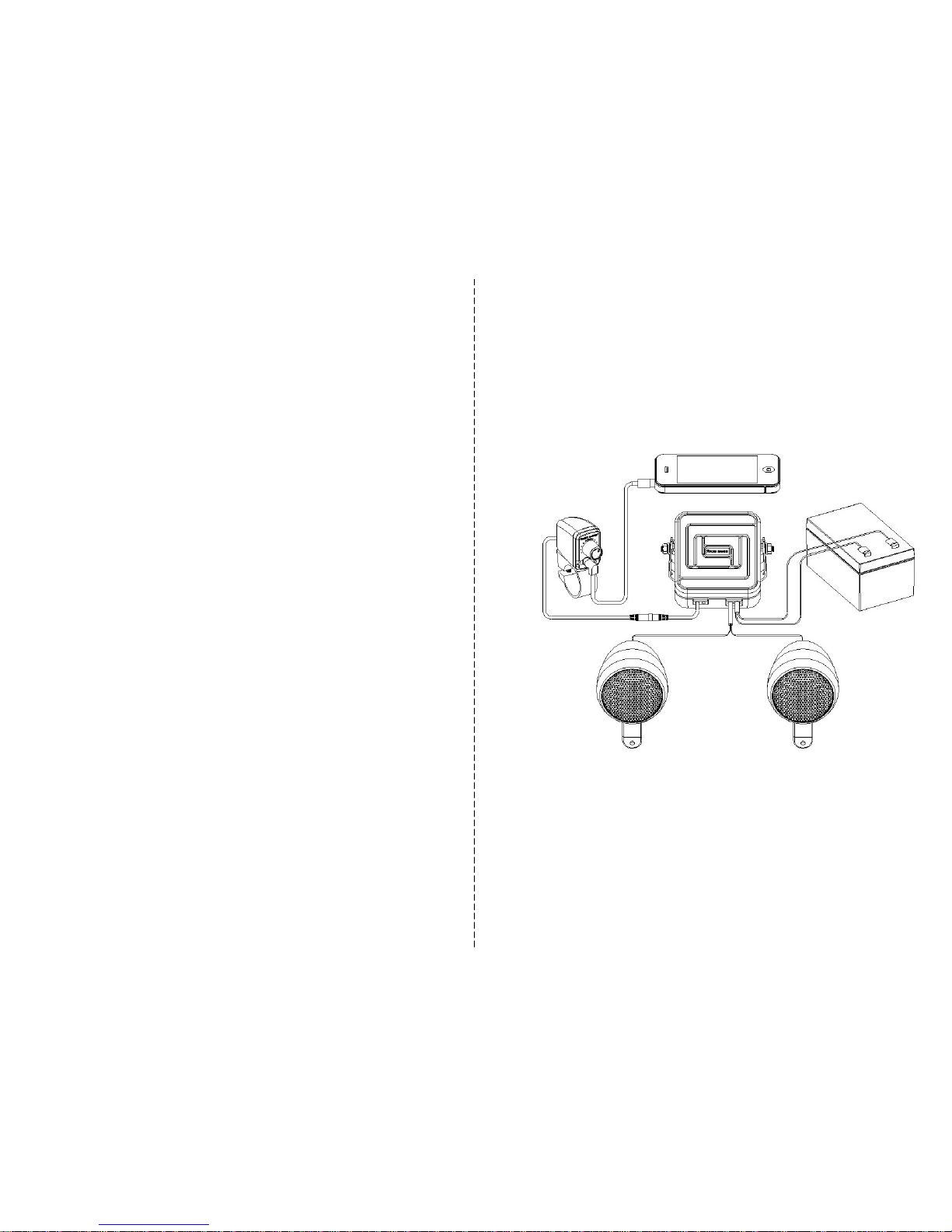
Moto-series
Installation Manual
Greness Enterprise Co ., Ltd.
1F, 19-1. Lane39. Sec2. Jianguo South Road, Taipei 10658, Taiwan, R.O.C
TEL: +886-2-2707-5741 FAX: +886-2-2707-4992
Website: www.greness.com.tw,
®Copyright 2011 Greness Enterprise Co., Ltd. All rights reserved.,
All content subjects to modificatio
n without notice.
Motorcycle / ATV Specialised Outdoor Audio System
Page 2

1. Introduction
The Moto ser ies pr ovides everything y ou require t o s etup a com plete audio system. It is specially
designed to provide the max imum outdoor music entertaining experience t o the users. It offers high
quality music experiences and 4 different us er-friendly means of installatio n. The audio system can
be installed on a variety of mobile vehicles, including motorcyc les, ATV, UTV, most of the watercrafts
CONTENTS
1. Introduction ……………………… ………………………...………… …………………………… ……….1
2. Applications …………………… ……………………………………… ………………………………… …1
3. Safety Precaution ………………………………… ……………………………… ………………………..1
4. Specification ……………… ………...………………………… ………………………………………… ...2
5. Parts list …………………………… ……………………………… ………………………………………..3
6. Select the best location for mounting ………… ………………………………………………………….4
7. Amplifier Installation Manual ……………………………...……… …………………………… …………4
8. Loudspeaker Installation Man ual …………………………………… ………………………………… …5
9. Appendix ……………………… ……….………………...……… ………………………………… ………6
2. Applications
Moto series are built to withstand tough challenges in different outdoor / marine environments. They
can be installed at locations with high humidity an d high chance of water s plashes. Vehicles suitable
for installation include:
Motorcycle
All terrain ve hicle (ATV)
Personal watercraft (PWC)
Snowmobil e
Utility task vehicle (UTV)
Golf car
Recreational vehicle (RV)
Boats / yachts
1
6
3. Safety Precaution
Read the manual before installation. It contains important information for all users.
Turn off the main electricity supply before beginning the installation
For electric drill, e nsure it is connected to the ground properly and the area is fr ee of any liquid.
If any problem occ urs during the installation, please contact your local dealer for advice bef ore
9. Appendix
Item Qnty Description
A 1
Amplifier
B 1
Amplifier bracket
C 1
Volume control
D 1
Volume control clamp
E 2
Jet-engine speakers
F 2
Brackets (surface mount)
G 2
Clamps (handle bar mount), 7/8”
H 2
Clamps (handle bar mount), 1”
I 2
Speaker holders
J 2
Stainless steel brackets
K 2
Pan head, Phillips, type C, 4x15 mm
L 2
Pan head, Phillips, type C, 4x25 mm
M 4
Speaker nuts, 4x7mm
N 6
Pan head, Phillips, type A, 4x12 mm
O 2
Pan head, Phillips, type A, 4x6 mm
P 2
Hex nuts 4.85x3.8 mm
Q 2
Lock washers 6.3x10 mm
R 2
Lock washers 5.8x10 mm
S 4
Flat washers 6.3x10 mm
T 2
Square head bolts, 4.85x10 mm
U 2
Hex point, type A, 6.3x19 mm
V 2
Truss head, Phillips, type B, 4x13
mm, spare for plastic mount.
W 1
EPDM gasket, 50Lx15Wx1.5H mm
X 1
EPDM gasket, 82Lx15Wx1.5H mm
Y 1
Volume con trol, Pan head, Phillip
s,
type C, 4x25 mm
Moto-620 / 625 / 630
Moto-820 / 825 / 830
Item Qnty Description
A 1
Amplifier
B 1
Amplifier bracket
C 1
Volume control
D 1
Volume control clamp
E 4
Jet-engine speakers
F 4
Brackets (surface mount)
G 4
Clamps (handle bar mount), 7/8”
H 4
Clamps (handle bar mount), 1”
I 4
Speaker holders
J 4
Stainless steel brackets
K 4
Pan head, Phillips, type C, 4x15 mm
L 4
Pan head, Phillips, type C, 4x25 mm
M 8
Speaker nuts, 4x7mm
N 12
Pan head, Phillips, type A, 4x12 mm
O 4
Pan head, Phillips, type A, 4x6 mm
P 2
Hex nuts 4.85x3.8 mm
Q 2
Lock washers 6.3x10 mm
R 2
Lock washers 5.8x10 mm
S 4
Flat washers 6.3x10 mm
T 2
Square head bolts, 4.85x10 mm
U 2
Hex point, type A, 6.3x19 mm
V 2
Truss head, Phillips, type B, 4x13
mm, spare for plastic mount.
W 1
EPDM gasket, 50Lx15Wx1.5H mm
X 1
EPDM gasket, 82Lx15Wx1.5H mm
Y 1
Volume con trol,
Pan h ead, Ph illips,
type C, 4x25 mm
The amplifier has auto on/off system to help saving power and has a self protective thermal fus e
device t o p rotect both amplifier and loudspeakers from short circuiting. It is compatible with audio
devices that have an AU X-IN 3.5m m jack and the sys tem is hi ghly adapted to condition changes in
the environment, including humidity and temperature. Complete with waterproof accessories, the
amplifier and loudspeakers c arry IP 68 rating and IP 65 ratin g respectively.
Page 3
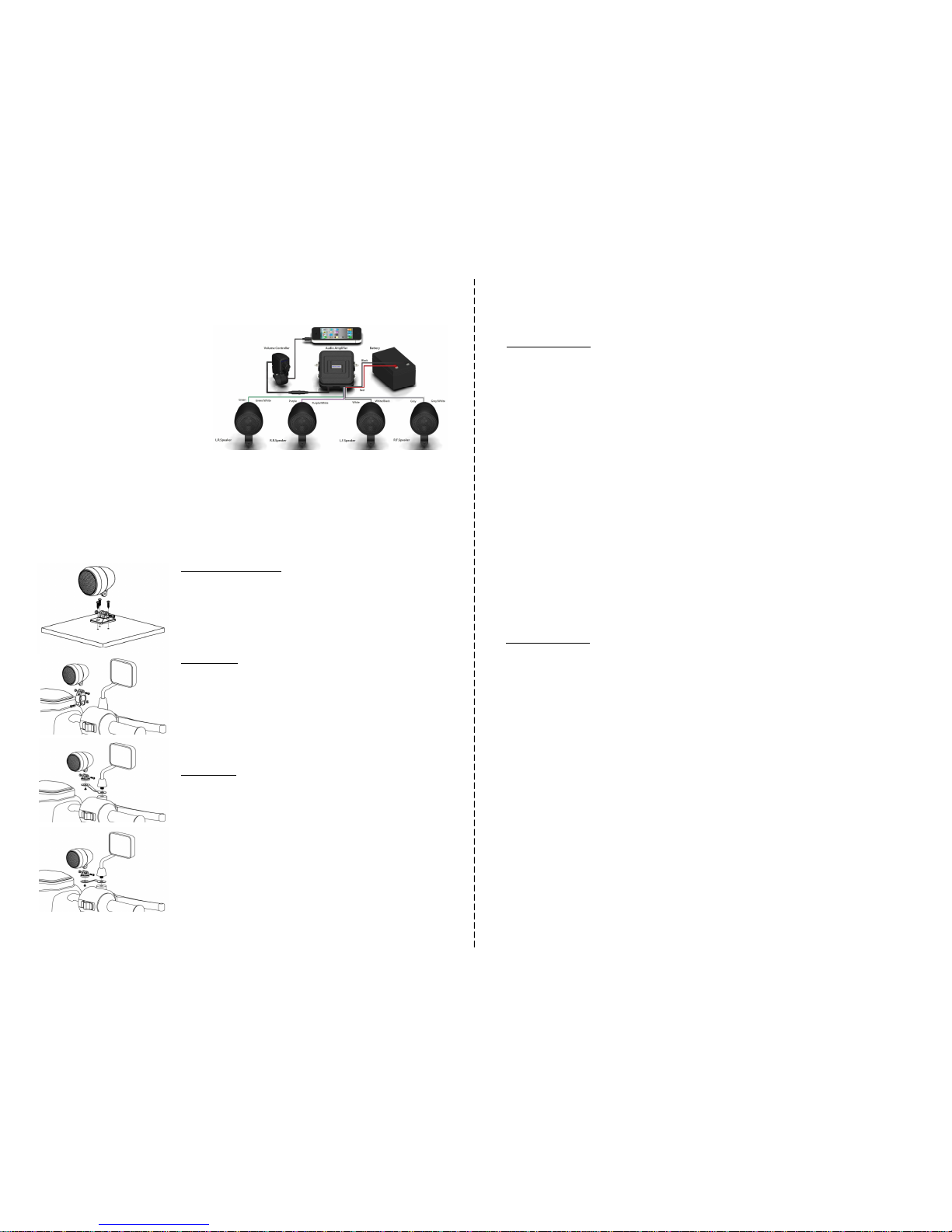
Figure 5. Wiring diagram of Moto
-82
0 / Moto-
825 / Moto-830.
1. Red wire - Audio am plifier power (+).
Connect the r ed wire directly to the positive (+)
terminal of the battery.
2. Bl ack wire - Audio amplifier ground (-).
Connect black wire to the negative (-) terminal
of the battery.
3. Grey wire - Connect the grey wire to the
positive (+) terminal of the right front speaker.
4. Grey/White wire - Connect the grey/white
wire to the negative (-) terminal of the right front
speaker.
5. W hite wire - Connect the white wire to the
positive (+) terminal of the left front speaker.
6. W hite/Black wi re - Connect the white/black
wire to the negati ve (-) term inal of the left fr ont
speaker.
7. Purple wire - Connect the purple wire to the
positive (+) terminal of the right rear speaker.
8. Purple/white wire - Connect the purple/white
wire to the negati ve (-) terminal of the right rear
speaker.
4. Specification
Moto-620 / 625 / 630
2 Channel 40 watts waterproof outdoor Class D A mplifier for iPod / MP3 / port able CD players or
any satellite radio system
Two jet-engine sp eakers including (2”/ 2.5”/ 3”for se lection) with 3 different avai lable mounting
styles
Waterproof and corr osion-proof amplifier case with mounting bracket
Waterproof volum e control with 6fit cable and 3.5m m mini plug
Protection :Thermal and short circuit protection and auto recovery feature
AUX-IN 3.5 mm jack with rubber cover
Automatically turn on power and automatically tur n off power (30 - 50 seconds)
Amplifier : IP68 rat ing / CE certificate / E-Mark / FCC / RoHS conformed
Speaker : IP65 rati ng / IEC-268-5 (100 hrs tested) / RoHS conformed
Frequency response : 20 Hz – 20000 Hz
Impedance : 4 ohms
Output power : 20W /Chennal 4 ohm load from 12V DC
30W/Chennal 4 ohm load from 24V DC
Power supply : Fro m 10V - 26V DC
SNR : 98 dB / 12V 102 dB / 24V
5
2
1) Standard Flat Surface:
1. Mount the plastic bracket on the chosen flat surface with the
screws (4×12 mm) provided in the package
2. Hold the jet-engine speaker in position and secure the
mounting with a screw (4×15 mm) and a nut
3. Adjust the projecting angle of the speaker and tighten any
loose screws
2) Handle bar:
1. Select the a ppropriate mounting clamp fro m the package
2. Hold the jet-engine speaker in position and secure the
mounting to the clamp with a scre w (4×15 mm) and a nut
3. clamp it aroun d the handle bar
4. Adjust the angle of the clamp. Tighten t he clamp with a screw
(4×25 mm) and a nut.
5. Adjust the projecting angle of the speaker and tighten any
3) Mirror side:
1. Select the appropriate mount ing bracket from the package an d
dissemble the side mirror
2. Select the appropriate mounting style of the bracket. To
position the speakers at a higher level see depiction A; to
position the speakers at a low er level see depiction B
3. Hold the jet-engine speaker in position and secure the
mounting to the holder with a sc rew (4×15 mm) and a nut
4. Screw the holder to the stainless steel br acket with a 4×6 mm
screw and adjust the angle
5. Reassemble the side mirror on the stainless steel bracket as
A
B
8. Loudspeaker Installation
Moto-820 / 825 / 830
4 Channel 40 watts waterproof outdoor Class D A mplifier for iPod / MP3 / port able CD players or
any satellite radio system
Four jet-engine speakers including (2”/ 2.5”/ 3”for selection) with 3 different ava ilable mounting
styles
Waterproof and corr osion-proof amplifier case with mounting bracket
Waterproof volum e control with 6fit cable and 3.5m m mini plug
Protection :Thermal and short circuit protection and auto recovery feature
AUX-IN 3.5 mm jack with rubber cover
Automatically turn on/off power and automatical ly turn off power (30 - 50 seco nds)
Amplifier : IP68 rat ing / CE certificate / E-Mark / FCC / RoHS conformed
Speaker: IP65 ratin g / IEC-268-5 (100 hrs tested) / RoHS conformed
Frequency response : 20 Hz – 20000 Hz
Impedance : 4 ohms
Output power : 10W /Chennal 4 ohm load from 12V DC
15W/Chennal 4 ohm load from 24V DC
Power supply : Fro m 10V - 26V DC
SNR : 98 dB / 12V 102 dB / 24V
9. Green wire - Connect the green wire to the positive (+)
terminal of the left rear speaker.
10.Green/white wire - Connect the green/white wire to the
negative (-) terminal of the left rear speaker.
11. Black wire - Connect am plifier and volum e control through
a black 3.5 mini plug waterproof wire and then connect to MP3
player or i-Phone.
Page 4
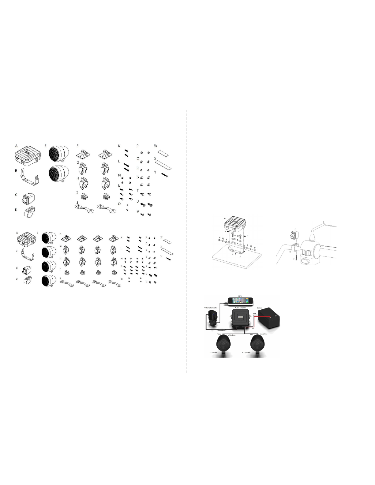
5. Parts List
Please check the parts and their quantity befor e installing your audio system. Contact your loca l
dealer if anything is missing as s oon as possible. For the list of all parts, please see the appendix
Figure 2.
Parts of
Moto-820
/ 825 / 830
.
Contents of all the parts included in the
Moto-8
20 package
Figure 1. Parts
of
Moto-620
/ 625 / 630
.
Contents of all the parts included in the Moto
-
620 package
6. Select the best location for mounting
Be awar e that Moto series can adapt different mounting styles and each follows a separate set of
installation instructions. The loudspeakers are designed to stand on top of a strong s urface. All
speakers are intended to be inst alled into a sturdy panel.
The surface/panel you select should have the appropriate strength to hold the unit firmly in place
after installation. Apart from the strength, consider the effects of shock, vibration, shear pressure and
movement in different directions have on the mounting surf ace/panel. If the surface is not sturdy
enough, the housing may be dislocated from its original position and it may be damaged. If y ou are
uncertain about the location o f your choice, contact the loca l dealer for advice.
7. Amplifier Installation Manual
Read the following installation manual c arefully befor e proceeding. If you are unfamiliar with wir ing
electronic devices, consult your local dealer or contract professionals. False wiring could damage the
amplifier and the rest of audio system.
Figure 4.
Wiring diagram of
Moto-620 / Moto-
625 /
Moto-630.
1. Red wi re - Audio amplifi er power ( +). Connect the
red wire directly to the positive (+) terminal of the
battery.
2. Black wi re - Audio amplifier ground (-). Connect
black wire to the negative (-) terminal of the battery.
3. G rey wire - Connect the grey wire to the positive
(+) terminal of the right speaker.
4. G rey/White wire - Connect the grey/white wire to
the negative (-) terminal of the right speaker.
5. White wi re - Connect the white wire to the positi ve
(+) terminal of the left speaker.
6. White/Black wire - Connect the white/black wire to
the negative (-) terminal of the left speaker.
7. Black w ire - Connect amplifier and volume control
through a black 3.5 m ini plug waterproof wire and
then connect to MP3 player or i-Phone.
4
3
Figure 3. Amplifier and volume control installation quick guide.
Select a st able and sturdy surface before beginning the process. Mount the amplifier unit as illustrated in the diagram (left) .
For reference to volume control installation, please see right. Ensure the right parts are used during installation. F or the parts
list, please see Parts List on page 3 and Appendix on page 6. Test the audio s ystem by playing music from your audio device.
If the green light comes on then rot ate the volume control knob to adjust the v olume. Contact your local dealer if the system
fails to function.
 Loading...