


REVISION HISTORY
LEGEND
WARNING
NOTE
DATEREVISION DESCRIPTION
Notes are used to highlight special operating conditions or steps of a
procedure.
Warnings are used to highlight procedures which, if not strictly
observed, may result in personal injury or loss of life.
Tips.
TIPS
1.0 Apr 20th 2018
User Manual

Revision History 2
Legend 2
GETTING STARTED 6
Introduction 7
Features 8
HDMI Support
SMA Support
Single Arm Design
More I/O
Heated & Temperature Controlled IMU
High Performance Gimbal Controller
Clean Design - Internal Wiring
Compact & Ultra Lightweight
Built For Inspection
Specications 11
Gremsy S1 Mechanical Components 12
Gremsy S1 I/O Connectors 13
Gimbal Mount: Connectors & Pinouts
Gimbal Controller: Connectors & Pinouts
Tilt Stage: Connectors & Pinouts
Gremsy S1 Electronic Diagram 19
What’s In The Box 20
Gimbal Mounting 21
Gimbal Mounting
Powering Up The Gremsy S1 22
Step 1
Step 2
Step 3
Status LED Indicator 23
Operation Modes 24
Gremsy S1 Has 2 Operation Modes
Gremsy S1 Supports
Working Operation
Swithching Between Modes
Installing Software / App 26
Using USB/BLUETOOTH Connection 27
Using USB Connection
Using BLUETOOTH Connection
CONTENTS

BALANCING 29
Mounting The Camera 30
Tilt Axis Front-Back Balance 31
Tilt Axis Vertical Balance 32
Roll Axis Balance 33
Pan Axis Balance 34
SOFTWARE - TUNING 35
Stiffness Tuning 36
General Method
Step 01 - Tilt Stiffness
Step 02 - Roll Stiffness
Step 03 - Pan Stiffness
Auto tuning 37
Filter 38
Gyro Filter
Output Filter
Default Values
Expert / advanced settings 39
Hold Strength
Gain
Default Settings
Follow Mode Settings 40
Speed
Smooth
Window
Tilt Lock
Airborne
Rotation Limit 41
Up Limit
Down Limit
Roll Offset
IMU Sensor 42
Gyro Calibration
Accelerometer Calibration

CanlinkConguration 44
Introduction
CANLINK Connection
Using CANLINK
Fine Trim The Horizon
Step 1:
Step 2:
Step 3:
REMOTE CONTROL 46
SBUS/PPM Settings 47
Receiver Connection
Channel Setting
JR/SPEKTRUM Settings 48
JR / Spektrum Satellite Receiver Connection
Channel Settings
UPGRADING FIRMWARE 49
How To Upgrade 50
TROUBLESHOOTING 51

GETTING STARTED

INTRODUCTION
S1 is the upgraded version of Gremsy T1 with many added features built
specically for inspection. Having HDMI , SMA port built in and one arm design
allows camera set up a lot easier. Moreover its compact and ultra lightweight
translate to longer ight time thus making it one highly demanded gimbal for
industrial experts.
7
GETTING STARTED
USER MANUAL
FEATURES
HDMI SUPPORT
SMA SUPPORT
SINGLE ARM DESIGN
Having HDMI ports on the gimbal allows camera setup more convenience and
clean.
Having SMA ports on the gimbal allows GPS antena of some special cameras
(Dual Pro R, for example ) could be connected easily without having the antena
cable get twisted during gimbal operation
Having single arm design enable light weight but still maintain rigidity and allow
camera set up easier.
8
GETTING STARTED
USER MANUAL
MORE I/O
HIGH PERFORMANCE
GIMBAL CONTROLLER
HEATED & TEMPERATURE
CONTROLLED IMU
Having more I/O allows user more exibilities and connections to interface with
external devices and third party products.
gMotion Controller, designed and made by Gremsy based on a 32 bit high
performance ARM microprocessor providing fast response and accurate
calculation. Sensor data and motors correction are updated as fast as 2000
times per second to enable incredibly smooth footage.
Heated and temperature controlled IMU sensor with advanced 6-point calibration
allows reliable performance even in extreme weather. Temperature is maintained
within 0.2 degrees Celsius accuracy.
9
GETTING STARTED
USER MANUAL
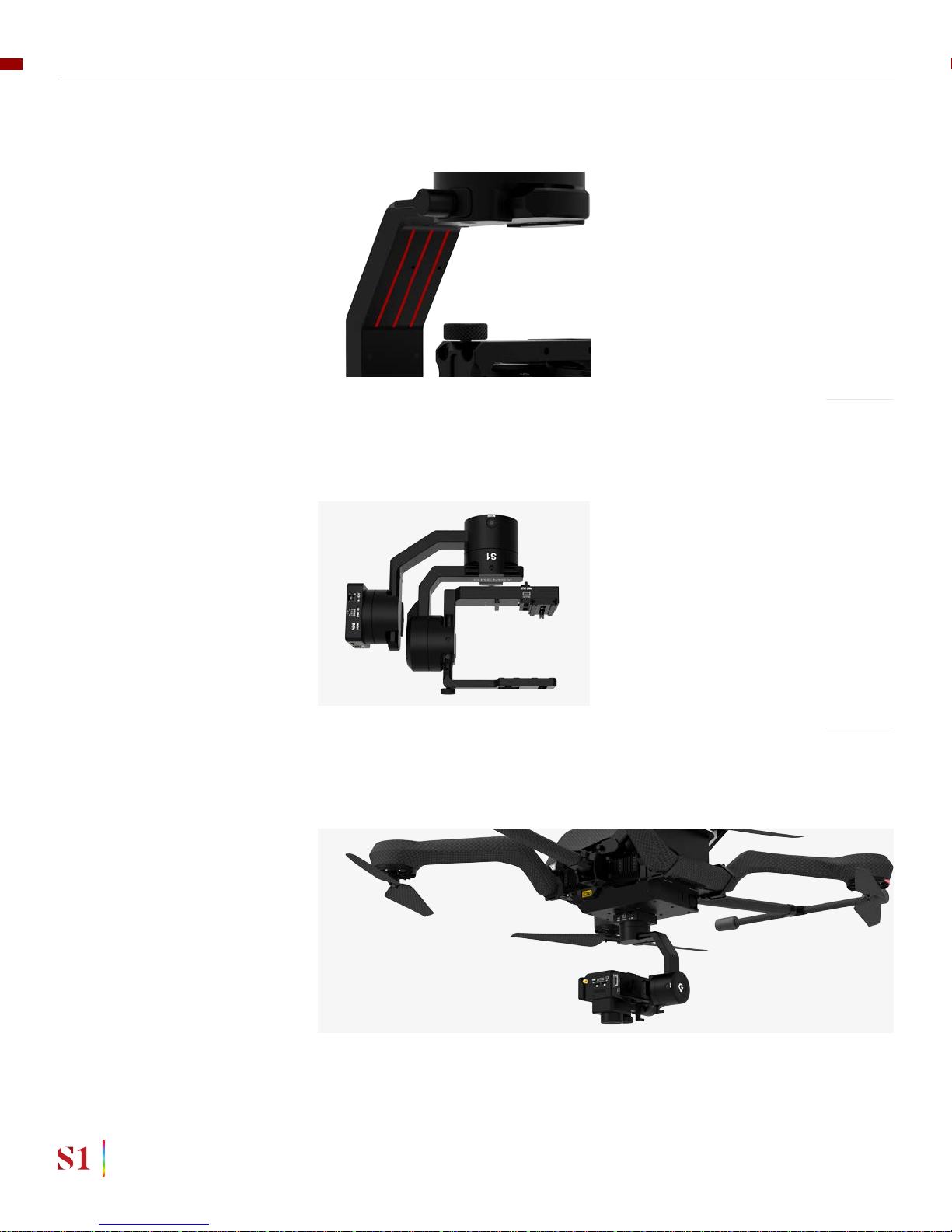
COMPACT & ULTRA
LIGHTWEIGHT
BUILT FOR INSPECTION
CLEAN DESIGN - INTERNAL
WIRING
Small in hand, powerful in the sky. The slimmed down S1 is small enough to t
into your backpack and take anywhere, yet strong enough to handle up to 1.5 lbs
payload.
S1 has powerful built-in functions that are completely compatible with thermal
and zoom cameras, dual camera to perfectly fulll their duties with minimal setup
and equipment.
No exterior wires, more solid. This clean design helps the S1 overcome wind
resistance with ease to bring out the best video quality while staying agile.
10
GETTING STARTED
USER MANUAL

SPECIFICATIONS
Product Name
System Type
Weight
Camera Cage (Standard) (W X L X H)
Construction
Input Voltage
Working Current
Connection
Payload
OS Platform Supported
Single Operator
Dual Operator
Pan Range
Tilt Range
Roll Range
Gremsy S1
3-Axis Digital Gyro-Stabilized
1.65 lbs / 750 g
120mm x 65mm x 72mm
All Aluminum
14 – 52V
Static Current 300mA @12V
Dynamic Current 600mA @12V
Locked Motor Current Max 3.5A @12V
USB, CAN, UART, BLUETOOTH
1.5 lbs / 700 g
Windows / Mac / iOS / Android
Follow Mode
SBUS / Spektrum / PPM / Lightbridge 2
+/- 160 degree
+/- 90 degree
+/- 45 degree
11
GETTING STARTED
USER MANUAL
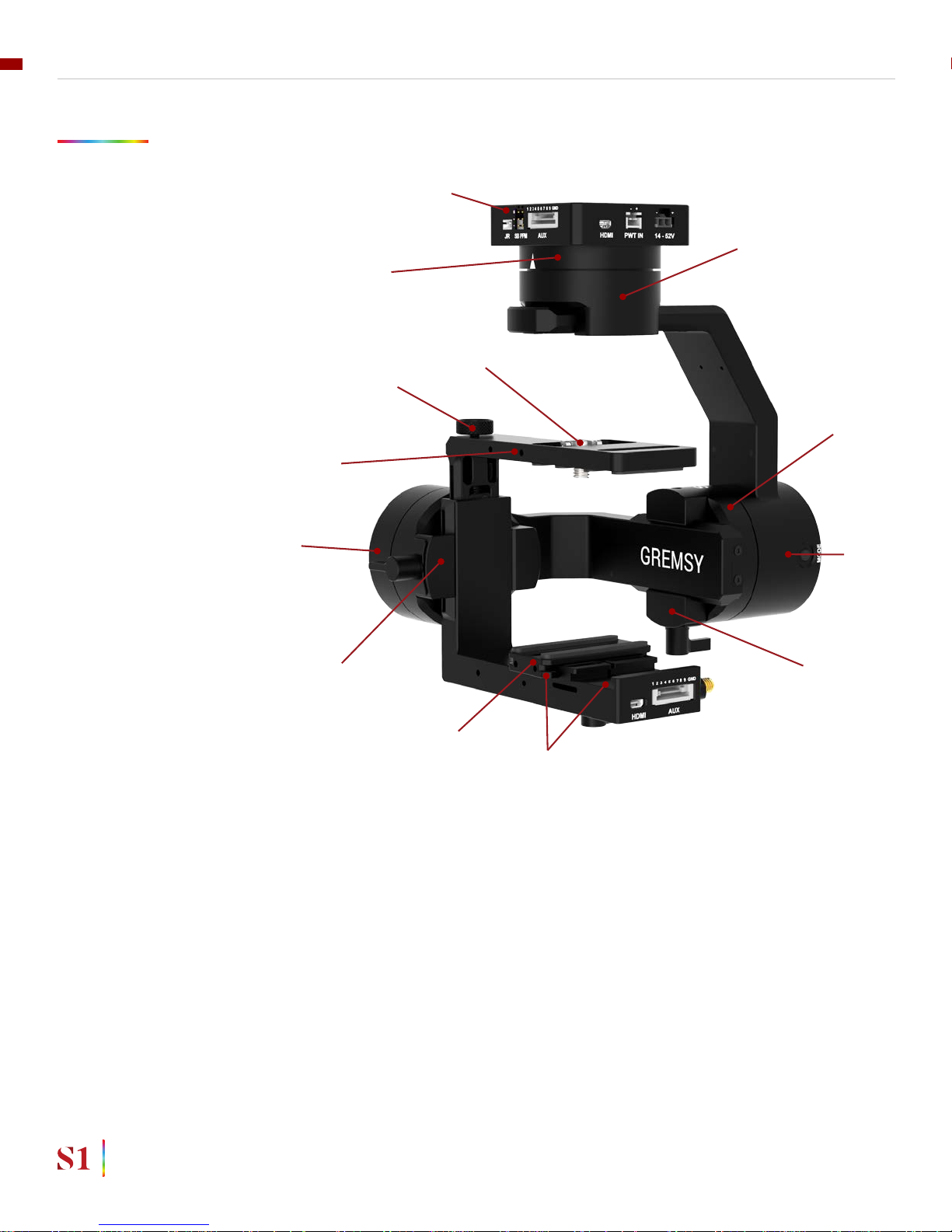
GREMSY S1 MECHANICAL COMPONENTS
01. Gimbal mount
02. Pan motor
03. Pan adjustment
04. Roll motor
05. Gimbal controller
06. Roll adjustment
07. Tilt motor
08. Tilt top bar
09. Camera plate
10. Tilt front- back adjustment
11. Tilt vertical adjustment
12. Top camera screw
13. Top bar adjustment knob
01
02
03
04
05
06
09
10
11
12
13
07
08
12
GETTING STARTED
USER MANUAL
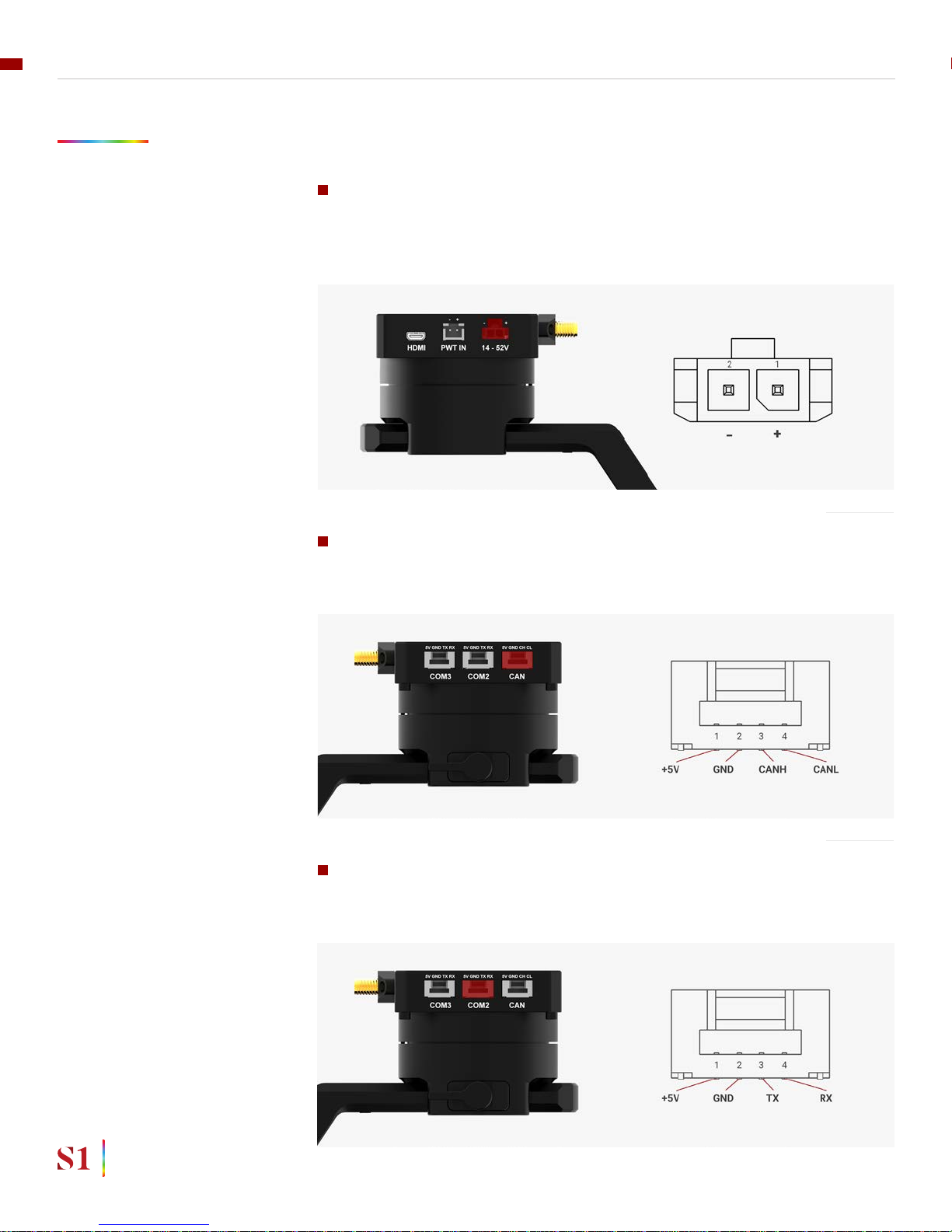
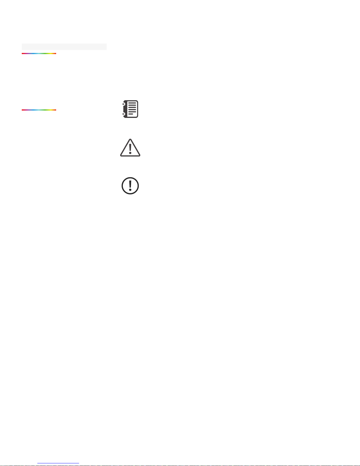
GREMSY S1 I/O CONNECTORS
GIMBAL MOUNT:
CONNECTORS & PINOUTS
POWER: to get power directly from external batteries of the drone or other
power supply. Voltage input range from 14V to 52V and is down converted to a
stable 12V by the internal circuit to provide power to gimbal and accessories.
Connector type: MOLEX MICROFIT 3.0 2 pin
CAN: to interface with CAN bus on DJI Flight controller or another module
that uses CAN bus.
Connector type: JST SM04B-ZESS-TB
COM2: to interface with Pixhawk or Pixhawk 2 via Mavlink protocol or other
modules that use serial protocol (UART).
Connector type: JST SM04B-ZESS-TB
13
GETTING STARTED
USER MANUAL
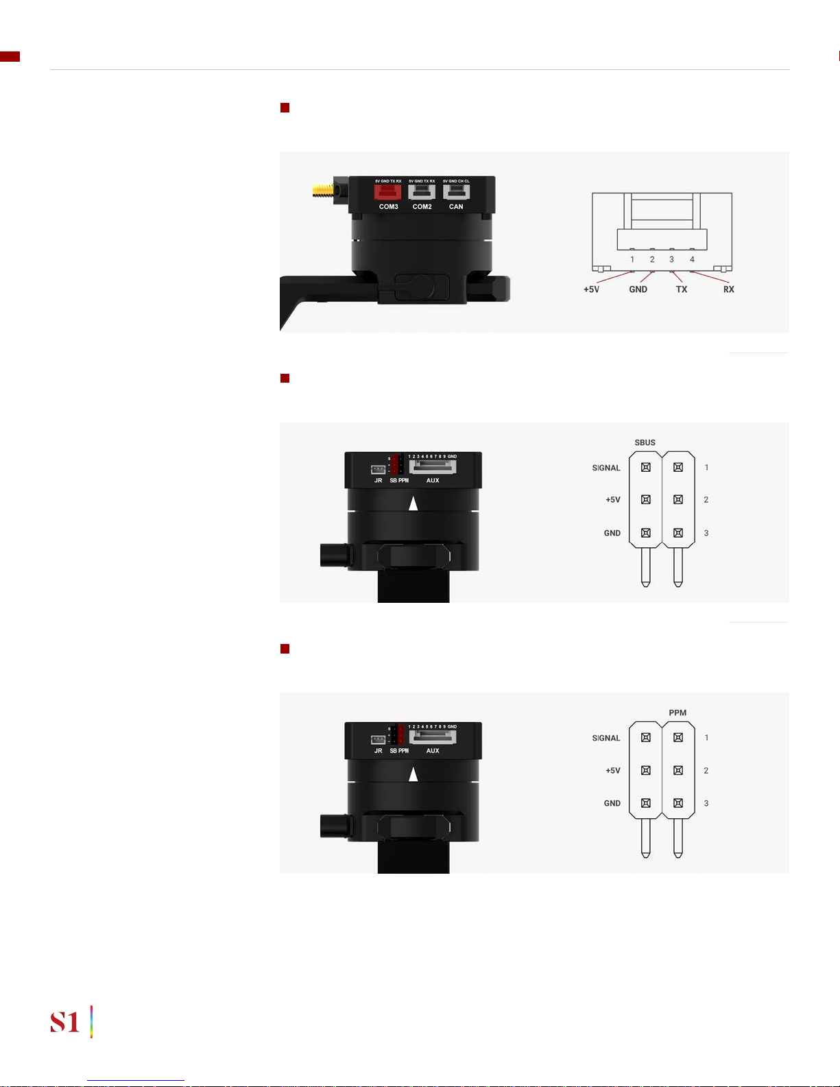
COM3: to interface with other modules that use serial protocol (UART).
Connector type: JST SM04B-ZESS-TB
SBUS: to interface with other modules that use serial protocol (UART).
Connector type: 3 pin, 2.54mm pitch
PPM: To interface with PPM receiver.
Connector type: 3 pin, 2.54mm pitch
14
GETTING STARTED
USER MANUAL
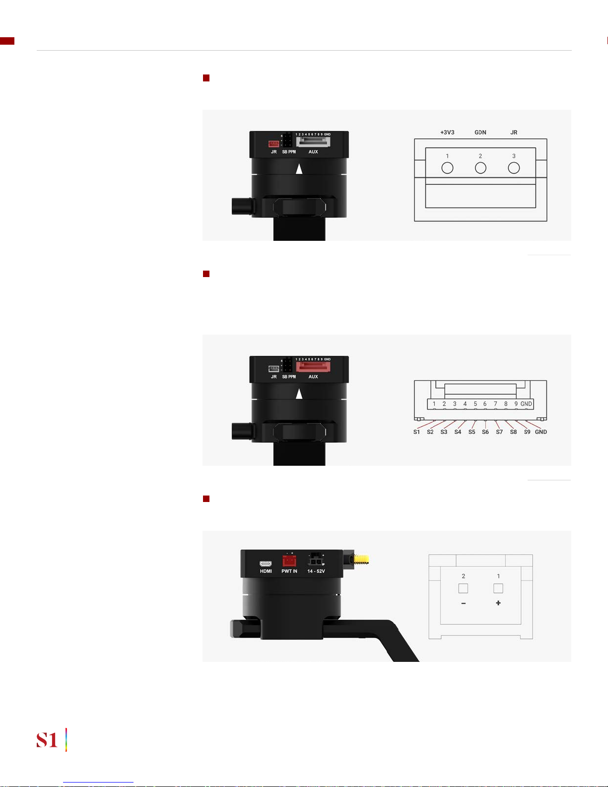
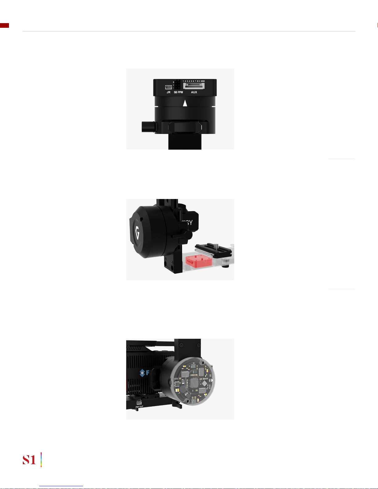
JR: to interface with JR/SPEKTRUM satellite receiver.
Connector type: JST S3B-ZR
AUX: There are S1, S2, S3, S4, S5, S6, S7,S8, S9 optional signal (0.2A max) ,
GND (1A max) for users to connect to other devices such as AV signal or camera
trigger...This port is internally connected to AUX port on the tilt stage.
Connector type: JST SM10B-ZESS-TB
PWT IN: To provide input power to PWR OUT of tilt stage .This port is internally.
Connector type: JST S2B-XH-A
15
GETTING STARTED
USER MANUAL
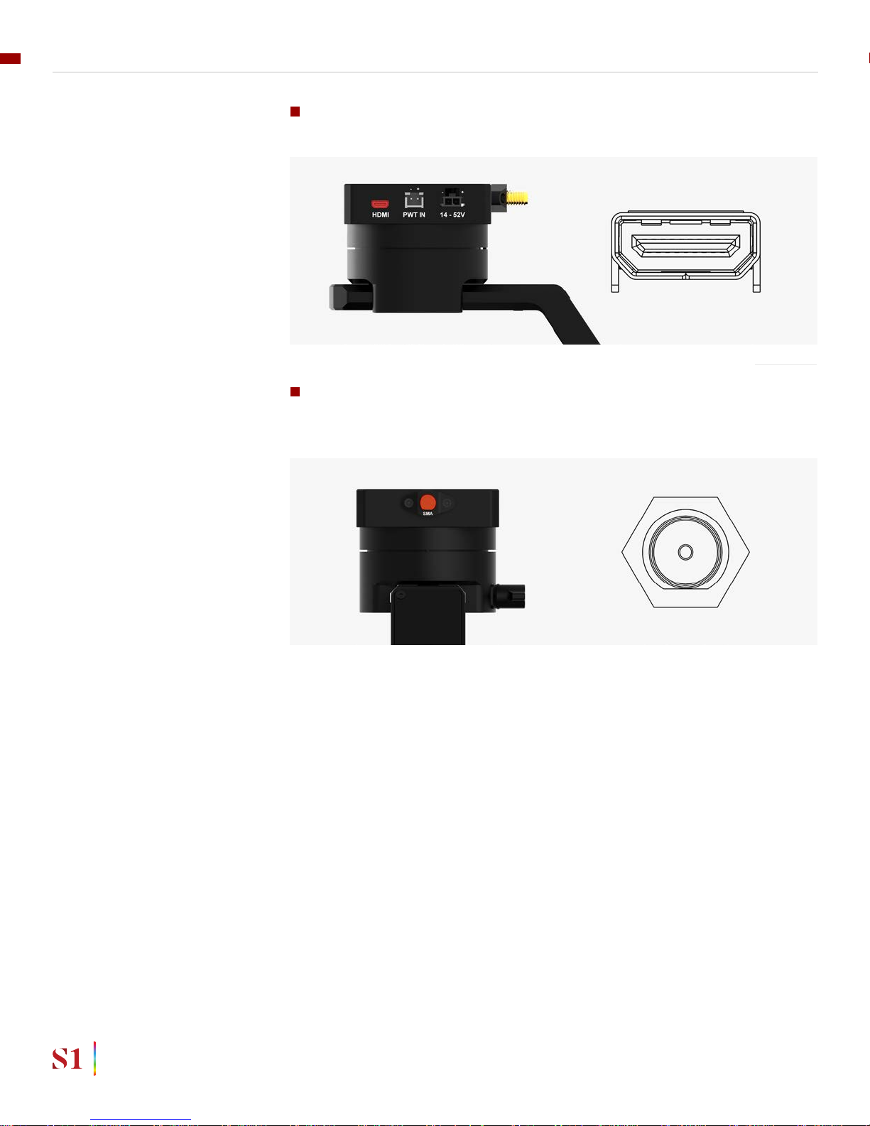
HDMI: HDMI output from tilt stage.
Connector type: Micro HDMI
SMA: To receive SMA signal from tilt stage `..This port is internally connected
to SMA port on tilt stage.
Connector type: SMA
16
GETTING STARTED
USER MANUAL

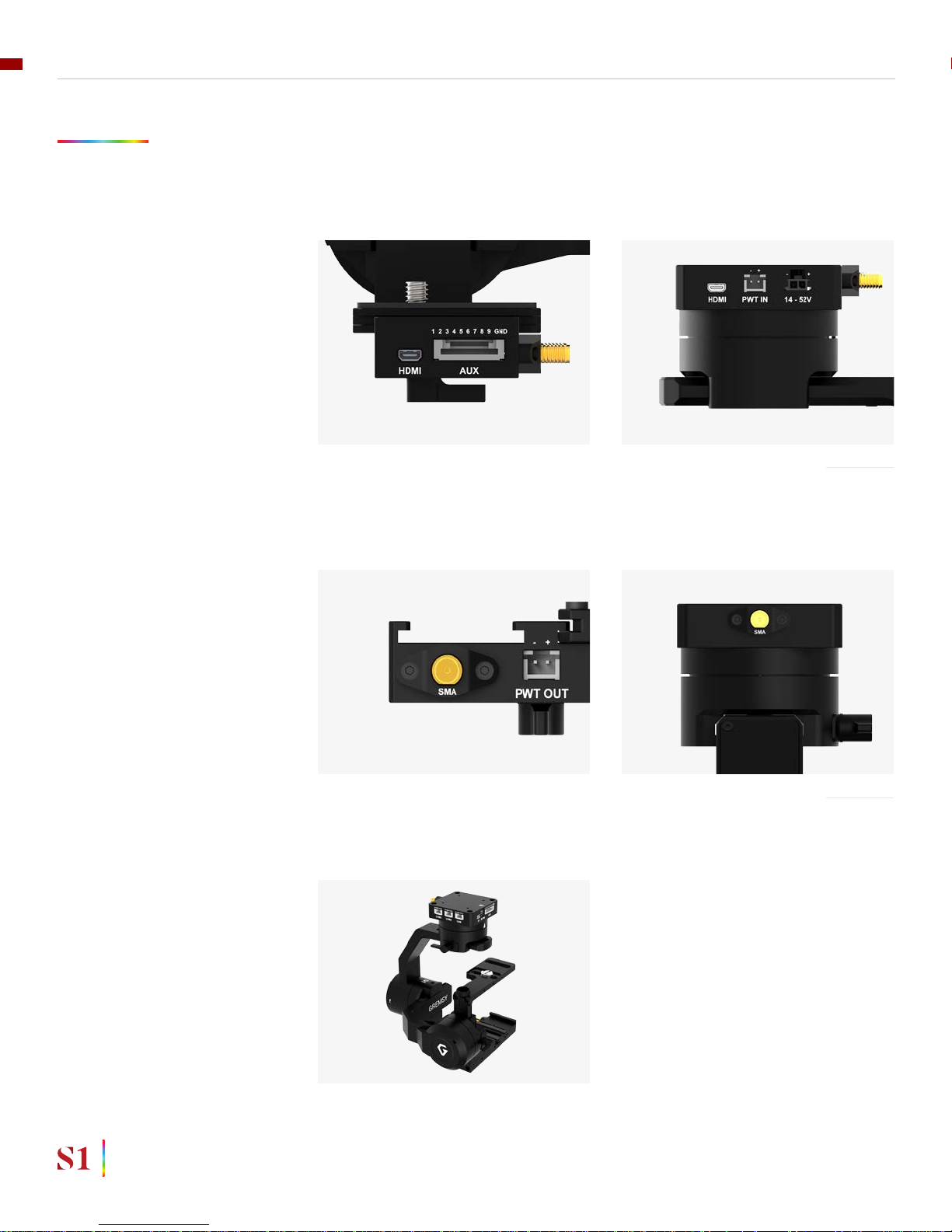
GIMBAL CONTROLLER:
CONNECTORS & PINOUTS
TILT STAGE: CONNECTORS &
PINOUTS
USB: to interface with computer or upgrade rmware.
Connector type: Micro USB TYPE B
AUX: There are S1, S2, S3, S4, S5, S6, S7,S8, S9 optional signal (0.2A max) ,
GND (1A max) for users to connect to other devices such as AV signal or camera
trigger...This port is internally connected to AUX port on the gimbal mount.
Connector type: JST SM10B-ZESS-TB
PWT OUT: To get power input from PWT IN port on the gimbal mount .This port
is internally connected to PWT IN port on the gimbal mount.
Connector type: JST S2B-XH-A
17
GETTING STARTED
USER MANUAL

HDMI: HDMI input.
Connector type: Micro HDMI
SMA: SMA input.
Connector type: SMA
18
GETTING STARTED
USER MANUAL

GREMSY S1 ELECTRONIC DIAGRAM
19
GETTING STARTED
USER MANUAL

WHAT’S IN THE BOX
01
02
A B C D E F G
03
A. Micro USB Cable
B. Power Supply Cable
C. Canlink Cable For Pixhawk
D. Canlink Cable For DJI A3/N3
E. Sbus Cable
F. Auxiliary Cable
G. Canlink Cable For DJI A2/ Naza V2 / Wookong
x1
x1
x1
x1
x1
x2
x1
01. GREMSY S1 GIMBAL 02. SLIDE CAMERA & CAMERA SCREW
03. GREMSY S1 CABLES
20
GETTING STARTED
USER MANUAL

GIMBAL MOUNTING
GIMBAL MOUNTING
There are two ways to mount the gimbal:
Using 4x M3 to mount the top part (4 threads are arranged 32mmx32mm in
squared pattern) onto the frame or damping isolator
Using 4x M3 to mount the top part (4 threads are arranged 51mmx51mm in
squared pattern) onto the frame or damping isolator.
21
GETTING STARTED
USER MANUAL

STEP 1
STEP 2
STEP 3
POWERING UP THE GREMSY S1
Always start the gimbal with a balanced camera set up otherwise after
initialization the controller will return an error followed by a red color
indicator.
If the status LED is solid red, something is wrong with the gimbal and
motors can not start. Connect to the software/apps to check details of the
error message.
Make sure the gimbal is mounted to the drone and its power port is already
connected to the power supply correctly.
If the status LED is blinking green, the gimbal is ready for use. By default, the
gimbal is in Follow mode if the motors are turned ON by the Function Button.
Wait about 5 seconds, do not touch the gimbal or camera. The gimbal will
perform series of rotations and self tests .
Read “LED STATUS INDICATOR” in next section for more information.
NOTE
NOTE
After connecting to the power supply, the gimbal will perform series of
alignments, self tests, which last about 5 seconds and will determine the status
of the gimbal, indicated by the Status LED color. During this time, don’t touch the
gimbal or camera.
22
GETTING STARTED
USER MANUAL

STATUS LED INDICATOR
01
02
03
04
05
06
07
08
09
10
11
12
Low Battery
System Error (Motor or IMU)
Calibrating
System Boot
System Ready
Lock Mode
Follow Mode
Remote with Lock Mode
Remote with Follow Mode
Auto-tuning in process
Canlink with Lock Mode
Canlink with Follow Mode
Blink
Solid
Blink
Solid
Blink
Blink
Solid
Blink
Solid
Blink
Blink
Solid
STATE LED STATUS DESCRIPTION
23
GETTING STARTED
USER MANUAL

OPERATION MODES
GREMSY S1 HAS 2
OPERATION MODES
GREMSY S1 SUPPORTS
WORKING OPERATION
SINGLE OPERATOR: using FOLLOW mode.
DUAL OPERATOR: a second operator can use a Remote Controller (SBUS,
SPEKTRUM, PPM) to control gimbal’s movement.
LOCK MODE: is a stabilization mode where the camera maintains orientation
independently of the rest of the gimbal and the orientation can be changed by an
external control signal from remote control.
FOLLOW MODE: in this mode, the camera will mimic the operator’s movement
and allows one person to control camera tilt and pan without using an external
device like a remote control.
Gremsy S1 has 1 working operation: NORMAL
24
GETTING STARTED
USER MANUAL

SWITHCHING BETWEEN MODES
Using function button
Using mode channel on remote control
POSITIONS
High
Midle
Low
MODES
Follow mode
Motors ON
Lock mode
Motors ON
Motors OFF
PRESS TIMES
Once time
2 times
3 times
Hold 3 seconds
4 times
MODES
Turn motors ON
Lock mode
Follow mode
Turn motor OFF
Calibrate Gyros
Using software/application
If there is a remote control signal, changing modes or turning motors on/
off by other methods such as using the function button or software will not
take effect because the remote control signal has the highest priority and
override the command.
NOTE
25
GETTING STARTED
USER MANUAL

INSTALLING SOFTWARE / APP
Mobile apps are available in App Store and Google Play
App name: gTune
Searching: “gremsy gtune”
Desktop software
Download at:
www.gremsy.com -> Support -> Product Support -> Gremsy S1
26
GETTING STARTED
USER MANUAL

USING USB CONNECTION
USING USB/BLUETOOTH CONNECTION
To congure and monitor data of Gremsy software/app either USB/BLUETOOTH
connection is required.
Make sure the Silab USB driver is already installed. The driver can be
found at:
www.gremsy.com -> Support -> Product Support -> Gremsy S1
1 - Power ON the S1.
2 - Connect USB cable from gimbal controller to Mac/PC.
3 - Run the gTuneDesktop software.
4 - On Connection Tab, select the Serial option.
5 - Select the correct COM port in the list.
6 - Click on the “Connect” button.
STEPS TO CONNECT:
NOTE
27
GETTING STARTED
USER MANUAL

USING BLUETOOTH
CONNECTION
1 - Enable bluetooth adapter of mobile devices.
2 - Turn ON the gimbal and run the app
The application still supports WIFI connection like older version. In the case the
app is using WIFI as default, user can switch to bluetooth by the button on topright corner. The app will memorize the selected connection for later use.
After being accepted to use bluetooth, the app starts scanning for Gremsy
bluetooth integrated gimbals.
- If only one gimbal is found, it will be connected automatically.
- If more than one gimbal are found, a list of gimbals will be shown to let user
select the desired one
- If no gimbal found, an error will be shown.
STEPS TO CONNECT:
ON MOBILE APP
On Android: the OS also asks for Location Data permission for BLE
scanning feature (updated by Google since Android 6.0)
On iOS: the OS has issue with its bluetooth adapter itself sometimes, user
should check device’s quick settings and general settings to enable the
adapter, the bluetooth icon should appear on device’s status bar
NOTE
28
GETTING STARTED
USER MANUAL

BALANCING
To achieve the best performance from the S1, proper
balancing is necessary. Accurate balance is critical in
shots where the gimbal will be subjected to extreme
movements or accelerations. There are 3 axes that need
to be precisely balanced prior to powering up the gimbal.

MOUNTING THE CAMERA
Use a 1/4”-20 screw to secure the camera to the camera tray, then put the camera
to the gimbal and tighten the top bar screw slightly (if the camera has hot shoe
supported)
Mounting camera has large width on the second slot of the crossbar (Sony
A6000, Sony A6300)
Mounting camera has small width on the rst slot of the crossbar (Black magic
micro cinema camera, Flir Dual Pro R )
BALANCING
30
USER MANUAL

TILT AXIS FRONT-BACK BALANCE
When the proper front-back balance is achieved, the camera will stay level when
you remove your hands.
1. Loosen the thumbscrew underneath the camera tray and the top bar
adjustment knob. Then, gently slide the camera forward or backward until the tilt
axis remains level.
2. Tighten the thumbscrews to lock the camera and camera tray in position.
BALANCING
31
USER MANUAL

TILT AXIS VERTICAL BALANCE
When the proper vertical balance is achieved, you can rotate the camera in any
angle and it will stay at that position.
1. Rotate the tilt axis so that the lens is pointing upward.Then, loosen vertical
adjustment thumbscrew, gently slide the camera mount crossbar and the top bar
forward and backward until the camera remains pointing upward when released.
2. Tighten the vertical adjustment thumbscrew. Sometimes, the vertical balance
could not be achieved, the front-back balance should be re-checked in this case.
Tighten the top bar adjustment knob and camera top screw as well
BALANCING
32
USER MANUAL

ROLL AXIS BALANCE
1. Loosen the thumbscrew underneath the roll bar, then gently slide the roll bar
left or right until roll axis remains level.
2. Tighten the thumbscrew to lock the roll bar in position.
When the proper left-right roll balance is achieved, the camera will stay level when
you remove your hands.
BALANCING
33
USER MANUAL

PAN AXIS BALANCE
1. Loosen the thumbscrew, then gently slide the pan axis slider backward/forward
until it doesn’t swing and stay at any given position when released.
2. Tighten the thumbscrew to make sure pan axis slider is locked in position.
Tilt the gimbal about 20 degrees from the verticality, identify if the gimbal is front
heavy or back heavy. Slide the pan axis slider until the camera does not swing.
BALANCING
34
USER MANUAL

SOFTWARE - TUNING
After the camera is balanced on the Gremsy, it’s time to
ne tune some parameters for best performance.

STIFFNESS TUNING
GENERAL METHOD
STEP 02 - ROLL STIFFNESS
STEP 03 - PAN STIFFNESS
STEP 01 - TILT STIFFNESS
Stiffness setting has a signicant impact on the performance of the S1. This
setting adjusts the degrees to which the gimbal tries to correct for unwanted
camera movement and hold the camera stable. The higher you can run the
setting without vibration or oscillation, the better.
Start with a low value of 20 for all axes then turn motors ON. Slowly increase this
setting until you feel an oscillation in each axis, then reduce it until the oscillation
subsides. You can touch the camera to feel the oscillation during tuning. Increase
the stiffness setting 5-10 points at a time until oscillation appears then reduce 5
points until oscillation subsides.
Slowly increase this setting until you feel an oscillation in the roll axis, then
reduce the setting until the oscillation subsides. Pick the S1 up and make sure
there is no vibration when you move the gimbal around.
Slowly increase this setting until you feel an oscillation in the pan axis, then
reduce the setting until the oscillation subsides. Tilt the S1 about 20 degrees
from the verticality and make sure that no vibrations are presented.
Slowly increase this setting until you feel an oscillation in the tilt axis, then reduce
the setting until the oscillation subsides. Make sure there is no vibration when
tilting the camera up and down and when moving the gimbal in any orientation.
SOFTWARE & TUNING
36
USER MANUAL

AUTO TUNING
The Auto-Tune function provides automatic adjustment of each motor’s stiffness
value to nd a good setting, the process will take around 1-2 minutes. Please turn
motor ON prior to starting Auto-Tuning.
The settings found by Auto-Tuning are usually good to start with however,
it’s recommended to manually reduce stiffness if there is an oscillation in a
specic axis or increase stiffness in case if it is too low.
NOTE
SOFTWARE & TUNING
37
USER MANUAL

GYRO FILTER
OUTPUT FILTER
DEFAULT VALUES
FILTER
The purpose of the lters is to eliminate noise and vibration due to structural
resonances in the camera, lens, or gimbal.
Setting the lters too high or too low can cause signal disturbances that can
reduce the overall stabilization.
Denes the strength of the lter applied to Gyro sensor output. If the gimbal has
oscillations that cannot be corrected by adjusting stiffness settings, the Gyro
Filter is used to further tune the gimbal and remove the oscillation.
Denes the strength of the lter applied to motors output. If the gimbal has
oscillations that cannot be corrected by adjusting stiffness settings, the Output
Filter is used to further tune the gimbal and remove the oscillation.
1. If the gimbal is vibrating at a high frequency after tuning, increase the lter
values.
2. If the gimbal is oscillating or rocking at a low frequency after tuning, decrease
the lter values.
Gyro Filter
Output Filter
1
2
SOFTWARE & TUNING
38
USER MANUAL

HOLD STRENGTH
EXPERT / ADVANCED SETTINGS
DEFAULT SETTINGS
GAIN
There are some expert parameters that normally do not need to be adjusted.
Leave these parameters at default settings unless they are required for
troubleshooting.
If “Auto power adjustment” is enabled, “Hold strength” will be the minimum power
level required for the corresponding axis. The controller will automatically adjust
power level from minimum to maximum level depending on the displacement
between current angle and commanded angle.
If “Auto power adjustment” is not selected “Hold strength” will be constant power
level provided to the corresponding axis and should be adjusted manually. This
option is only recommended for advanced users.
For heavy cameras, it’s suggested to increase hold strength for each
axis around 10% than the default value. If “Auto power adjustment” is
not selected “Hold strength” will be xed power level provided to the
corresponding axis and should be adjusted manually. This option is only
recommended for advanced users.
NOTE
HOLD STRENGTH
GAIN
AUTO POWER ADJUSTMENT: ENABLED
120
TILT
30
ROLL
30
PAN
30
Denes how fast each axis will return to commanded position. To reload default
expert settings just press “Default” in the expert menu.
SOFTWARE & TUNING
39
USER MANUAL
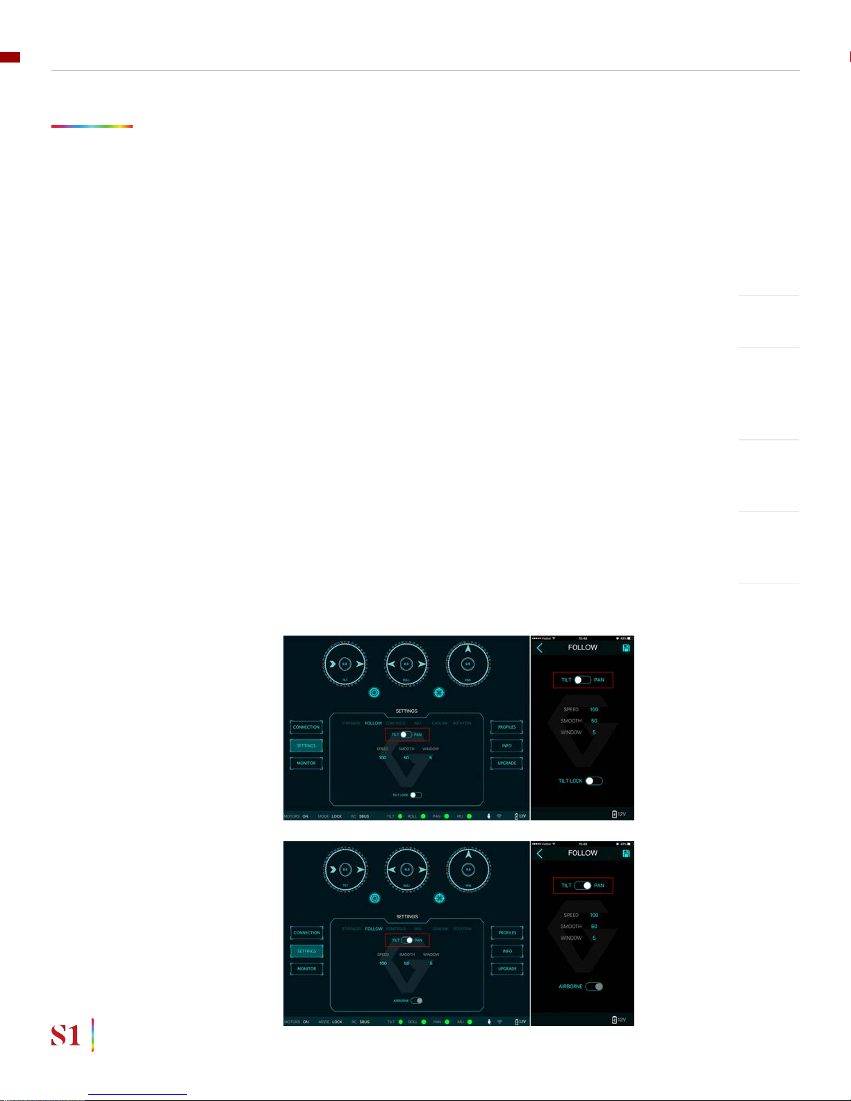
SPEED
SMOOTH
WINDOW
TILT LOCK
AIRBORNE
FOLLOW MODE SETTINGS
The most widely used mode of single operation is Follow mode where the gimbal
operator controls to pan and tilt of the camera. The camera movement will mimic
the user’s input from the top-mount while the footage remains stable. The follow
mode can be congured to be either very linear and robotic, or smooth and
cinematic.
Follow mode settings is available for Tilt axis and Pan axis.
Denes how fast camera will follow the movement.
Smooth out the camera movement by adjusting this parameter. The higher
the value is the smoother camera moves but at the expense of more delay in
following the movements.
When the movement is out of the window zone, the camera starts to move.
Within the window zone, the camera maintains its direction.
If this option is selected, the tilt axis will maintain its angle and only be controlled
by remote control.
This feature is not available on the S1.
SOFTWARE & TUNING
40
USER MANUAL

UP LIMIT
DOWN LIMIT
ROLL OFFSET
ROTATION LIMIT
Travel of Tilt and Roll axis can be limited using UP LIMIT and DOWN LIMIT. The
Pan axis keeps the ability to pan 360 degrees itself.
Set the up limit for Tilt or Roll axis (in 1 degree unit). The default values are -90 for
Tilt and -45 for Roll.
Set the down limit for Tilt or Roll axis (in 1 degree unit). The default values are 90
for Tilt and 45 for Roll.
Set the Roll offset (in 0.1 degree unit) is only applicable when there is no remote
control signal since remote control will override the roll angle. This is useful to
ne trim the horizon. The default value is 0.
SOFTWARE & TUNING
41
USER MANUAL

IMU SENSOR
The IMU sensor used in the S1 is a combination of a high precision 3 axis
gyroscope sensor and a 3 axis accelerometer sensor.
IMU board is enclosed in a weather proof case and being heated where the
temperature inside is controlled around 50°C with 0.2°C accuracy. Thanks to this
feature, gyro calibration is no longer required in most situations.
In order to provide extra high precision data output, the IMU is performed 6-point
calibration at Gremsy factory.
The S1 controller has a special algorithm to provide attitude estimation based on
input data from the IMU sensor. This attitude estimation helps the controller to
command motor output to compensate for camera movement.
SOFTWARE & TUNING
42
USER MANUAL

GYRO CALIBRATION
ACCELEROMETER
CALIBRATION
Thanks to temperature controlled and heated IMU, gyro calibration is not
necessary as the gyro was calibrated at the factory and the temperature inside
IMU remains constant around 50 degrees. However, if you notice drift during
operation in extreme weather (below -20C or above 50C) please re-calibrate the
gyro.
CALIB AT STARTUP: this feature is not available on the S1
After Gyro Calibration, Gyro Offset X, Y, Z will change to a new value
depending on the temperature.
NOTE
Do not use this function, please contact Gremsy Support Engineers.
Accelerometer sensor was calibrated properly at the factory to achieve
accurate horizon level with special and precise equipment. Users do not
need to do this unless it’s required for troubleshooting.
WARNING
SOFTWARE & TUNING
43
USER MANUAL

CANLINK CONNECTION
INTRODUCTION
USING CANLINK
CANLINK CONFIGURATION
FINE TRIM THE HORIZON
DJI FC
PIXHAWK
Connect the cable from CAN port on hyper quick release to CAN port on
COMPASS/GPS module on DJI FC
CANLINK is Gremsy’s proprietary solution to get information from the third party
ight controller to correct horizon drift.
Without CANLINK, our gimbal can maintain locked horizon most of the
cases where prolonged acceleration is not presented . When prolonged
acceleration is presented such as circular ight or prolonged bank turn
(where centrifugal force appears), horizon will drift after certain period of
time
In order to have Canlink worked properly, GPS module should installed
together with ight controller
Baudrate on Pixhawk should be set at 57600bps, 8 data bits, No Parity, 1
Stop bit (8N1)
Connect cable from COM2 port on hyper quick release to TELEMETRY 1/
TELEMETRY 2 on Pixhawk , Pixhawk 2. Once connected, the gimbal controller
will automatically send MAVLINK message to set attitude update rate of ight
controller at 10Hz
When the rst turn on the motor, make sure the pan axis is aligned with the
forward direction of the copter in order for the gimbal to calculate the attitude
correctly. After turning on the motor, the LED status turns to the pink color
indicating that CANLINK connection between gimbal and ight controller has
been established.
NOTE
NOTE
NOTE
There is tolerance between the gimbal’s IMU and ight controller’s IMU due to
mechanical mountings error or calibration error, for example, the gimbal’s frame
and the ight controller’ plane is not perfectly parallel with roll and pitch axis and
usually within 1-2 degree. To address this, we offer a way to ne trim the horizon
in 3 steps.
SOFTWARE & TUNING
44
USER MANUAL

STEP 1:
STEP 2:
STEP 3:
TURN MOTOR ON for the rst time, make sure the pan axis is aligned with the
forward direction of the copter during turning on the motor. LED status will
change to pink color.
Use radio control to move the pan to a position which is 180 degree away from
the forward position of the copter. Use a bubble level in order to observe the
horizon: adjust roll offset until it is level.
Use radio control to move the pan to a position which is 90 degree away from the
forward direction of the copter. Use a bubble level in order to observe the horizon:
adjust tilt offset until it is level.
If radio control is not available, switch gimbal in lock mode and rotate the
copter 180 degrees could achieve the same result.
If radio control is not available, switch gimbal in lock mode and rotate the
copter 90 degrees could achieve the same result.
TIPS
TIPS
SOFTWARE & TUNING
45
USER MANUAL

REMOTE CONTROL
S1 supports SBUS , SPEKTRUM and PPM receivers. There
are some parameters to be aware of before assigning
channels to the receiver.
SMOOTH: increasing this number will smooth out the
movement of the corresponding axis but will also cause
a delay.
SPEED MODE: when speed mode is selected, the
speed of the corresponding axis will depend on how
far the stick position is from the neutral position. It is
recommended that TILT and PAN channels should be set
to speed mode.
ANGLE MODE: when angle mode is selected, the
corresponding axis will move to the angle set by current
stick/knob position. It’s recommended ROLL channel
should be set to angle mode.

RECEIVER CONNECTION
SBUS/PPM SETTINGS
CHANNEL SETTING
Connect SBUS, PPM receiver to SBUS, PPM port which is located on the gimbal
mount.
The receiver must be connected to correct wires order. The SBUS/PPM
port has 5V output to power the receiver, please do not use external
power supply to power the receiver at the same time. Doing so may
damage the electronic inside the gimbal.
WARNING
There are 6 channels to assign: MODE, TILT, ROLL, PAN, TILT SPEED, PAN SPEED
Assign MODE channel rst then follow the order above because MODE channel
is used to change operating modes of the gimbal and should be assigned to a
3-position switch as follows:
Switch at high position: FOLLOW MODE , MOTORS ON
Switch at middle position: LOCK MODE , MOTORS ON
Switch at low position: MOTORS OFF
TILT and PAN channel should be in speed mode and ROLL channel in angle mode.
TILT SPEED or PAN SPEED could be assigned to the same channel and should be
assigned to throttle stick, dial, or other non-centering control on the transmitter.
Below is an example of channel assignment to the Futaba T8FG.
CHANNEL CONTROL NOTE
MODE
TILT
ROLL
PAN
TILT SPEED
PAN SPEED
5
2
4
1
4
6
SC
J2
T4
J1
J3
RD
3 positions switch
Speed mode
Angle mode
Speed mode
=
REMOTE CONTROL
47
USER MANUAL

JR / SPEKTRUM SATELLITE
RECEIVER CONNECTION
CHANNEL SETTINGS
JR/SPEKTRUM SETTINGS
Connect satellite receiver to the JR port on the gimbal mount as shown in the
picture. Make sure satellite receiver is already bound to the transmitter (RED led
is solid).
Choose 10 bit or 11 bit type resolution on the software and assign proper
channels as per SBUS settings.
REMOTE CONTROL
48
USER MANUAL

UPGRADING FIRMWARE
Only USB connection allows upgrading rmware. Refer to Section
“01. GETTING STARTED” for USB connection.
Make sure Silab USB driver is already installed. The driver
can be found at:
www.gremsy.com -> supports -> product support
NOTE

HOW TO UPGRADE
01 - Power on the S1.
02 - Connect USB cable from S1 controller to Mac/PC.
03 - Run the gTune Desktop software.
04 - In the software, select “Serial” option on “connection” tab.
05 - Select the port in the list.
06 - Click on the “Connect” button.
07 - Go to “Upgrade” tab.
08 - “Browse” to rmware le from your computer.
09 - Make sure the RF receiver (if available) is already removed.
10 - Click “Upgrade” button. The process will take about 2 minutes. When the
rmware is upgraded successfully, the S1 will be restarted automatically.
UPGRADING FIRMWARE
50
USER MANUAL

TROUBLESHOOTING

PROBLEM
Status LED is blinking red
Status LED is solid red during
startup
Status LED is solid red during
operation
Status LED is solid white after
start up
Gremsy T3 has oscillation in
one or more axes
Gremsy gimbal seems to be
drifting
Motors seem to be weak
Footage appears to wobble side
to side or up and down
POSSIBLE CAUSES
Low battery
Camera is not balanced well or
not installed
IMU cable is loose
Tilt motor cable or encoder
cable is loose
Roll motor cable or encoder
cable is loose
Pan motor cable or encoder
cable is loose
IMU sensor cable is loose
Excessive gyro drift
Stiffness setting is too high
Thumbscrew/top bar nut is not
tightened
Camera mounting is not stiff
enough
Filters settings are incorrect:
Gyro and output lter should
only be changed if other
methods of reducing oscillation
have failed
Gyro sensor is drifting too much
Stiffness is too low
Auto-power adjustment is not
enabled
Camera is not properly
balanced
Stiffness setting is low
SOLUTION
Recharge battery
Check camera balancing
Check in software for IMU sensor error, reseat IMU sensor connector
Check in software for Tilt error, re-seat tilt
motor connector and encoder connector
Check in software for Roll error, re-connect
roll motor connector and encoder cable
Check in software for Pan error, re-connect
pan motor connector and encoder cable
Re-seat IMU sensor connector
Re-calibrate
Reduce stiffness
Check tightening
Check camera mounting
Please read more in manual about Gyro lter
and output lter (Advanced settings)
Re-calibrate gyro
Increase stiffness
Check in Expert menu if Auto-power
adjustment is enabled or not
Check camera balance
Increase stiffness settings, start with the
axis which is poorly stabilized. Higher
Stiffness will achieve better stabilization.
The tuning process is described in the user
manual.
TROUBLESHOOTING
52
USER MANUAL
 Loading...