

GREMO 1250F, 1450F Workshop Manual

Gremo
1250F/1450F
Workshop manual
Gremo AB
311 51 Ätran
Sweden
Tel. +46 346–60515
Fax. +46 346–60342
www.gremo.com
info@gremo.se
Release
Workshop manual in
original
1450F 4.1EN
©Gremo 2019


Gremo 1250F/1450F Workshop manual
Contents
1 Introduction ............................................... 1
1.1 Introduction ....................................... 1
1.2 About the documentation kit ............. 2
1.3 Presentation Gremo 1250F/
1450F............................................... 4
1.4 Intended area of use ......................... 5
1.5 Operator requirements...................... 6
1.6 Safety regulations ............................. 6
1.7 Warning symbols and
information about risks .................... 7
1.8 Construction of the machine ............. 8
1.9 Definitions ......................................... 8
1.10 Environment.................................... 8
1.11 Location of type plates and
serial numbers ................................. 9
2 Safety regulations ................................... 13
2.1 General ........................................... 13
2.2 Clothing........................................... 16
2.3 Seat belt .......................................... 16
2.4 Emergency stop.............................. 17
2.5 Emergency exit ............................... 18
2.6 Emergency alarm............................ 18
2.7 Articulated joint lock........................ 18
2.8 Boarding the machine..................... 19
2.9 Inspection of parking brake............. 20
2.10 Driving........................................... 23
2.11 Crane operation ............................ 24
2.12 Parking/storage............................. 26
2.13 Trailer transport............................. 27
2.14 Service .......................................... 28
2.15 Oil leaks ........................................ 31
2.16 Oils ................................................ 31
2.17 Batteries........................................ 32
2.18 Welding Repairs............................ 32
2.19 If by accident the machine tips
over................................................ 33
2.20 In the event of fire ......................... 35
2.21 Warning signs ............................... 36
2.22 Recovery and towing .................... 44
2.23 Winch ............................................ 47
2.24 Engine and cab heater.................. 47
2.25 Anti-skid chains............................. 47
2.26 Bogie tracks .................................. 48
2.27 Risk of strain-related injury ........... 48
2.28 Noise............................................. 48
3.7 Fuel, requirement
specification................................... 56
3.8 Cleaning of Safety Glass
Windows ........................................ 57
3.9 Welding Repairs.............................. 58
3.10 Tyres — Air pressure:
Manufacturer’s
recommendations.......................... 60
4 Engine...................................................... 65
4.1 Fuel system..................................... 65
4.2 Cooling system ............................... 67
4.3 Intercooler ....................................... 68
4.4 Exhaust system with particulate
filter ................................................ 68
4.5 Replacing drive belts....................... 70
5 Transmission 1250F/1450F .................... 73
5.1 Transmission, gearbox.................... 73
5.2 Bogie axles...................................... 74
5.3 Parking brake.................................. 76
6 Electrical system.................................... 79
7.1 Structure of wiring diagram, wire
numbering, revision state .............. 79
6.2 Component position of fuse
groups and relays .......................... 80
7.3 Relay list.......................................... 85
7.4 Connector list .................................. 86
7 Hydraulic system.................................... 91
7.1 Hydraulic system, component
position .......................................... 91
7.2 Hydraulic oil return filters ................ 91
7.3 Breather filter hydraulic oil
tank ................................................ 92
7.4 Off-line filter hydraulic oil................. 92
7.5 Pressure check working
hydraulics....................................... 93
7.6 Pressure check,
transmission .................................. 97
8 Pressurised air system.......................... 99
8.1 General ........................................... 99
8.2 Pressurised air diagram.................. 99
3 Service, maintenance and technical
information.............................................. 49
3.1 Safety rules during service ............. 49
3.2 Service and maintenance ............... 51
3.3 Volume specifications ..................... 52
3.4 Working with oils ............................. 52
3.5 Oil, requirement
specification................................... 54
3.6 Antifreeze, requirement
specification................................... 55
9 Other equipment and optional
equipment.............................................. 101
9.1 Fire extinguishing system ............. 101
10 Wiring diagram .................................... 105
10.1 Power supply .............................. 105
11 Hydraulic diagram ............................... 173
11.1 Hydraulic diagram list.................. 173


Gremo 1250F/1450F Workshop manual 1 Introduction
1.1 Introduction
1 Introduction
1.1 Introduction
For you to get the most out of your Gremo machine as an
owner or an operator, it is very important that you maintain
and handle the machine correctly.
It is also very important that you familiarise yourself with
the performance and the restrictions of the machine.
It is especially important that the owner, the operator and
those who service the machine are familiar with the
contents of this Instruction Manual and study it thoroughly
before starting and driving, or before any preventive
maintenance work is done.
The responsibility for start, driving and service belongs to
the persons performing these steps! Please make yourself
well familiar with the controls and instructions before the
machine is used. It is too late to start looking in the
Instruction Manual when an accident has already
happened.
NOTICE
In order to find out about manual updates, it is important
to inform Gremo AB of any change of address or owner.
1
1 Introduction
1.2 About the documentation kit
1.2 About the documentation kit
1.2.1 About the Instruction Manual
Gremo 1250F/1450F Workshop manual
The Instruction Manual contains important information
about your new Gremo machine, about operating the
machine, safety when working and the machine's daily
checks. In addition, it offers many valuable tips that
facilitate your daily work.
Incorrect use of the machine may result in personal injury
and product or property damage. For this reason, read the
instructions carefully before operating the machine for the
first time.
The Instruction Manual should always be accessible in the
machine. If it disappears, a new one must be ordered
immediately from the manufacturer.
CAUTION
Never operate a machine without an instruction manual.
Refer to your supervisor or the manufacturer if there is
anything in the text that you do not understand or if you
cannot find what you are looking for.
1.2.2 About the service and maintenance manual
The service and maintenance manual provided with your
machine describes service points and measures that are
important to follow and carry out in order for your new
machine to work smoothly in the future.
1.2.3 About the spare parts catalogue
The spare parts catalogue provided with your machine
helps you to easily identify the right spare part. This unique
catalogue is also available online.
1.2.4 About the workshop manual
A workshop manual describing in detail extensive repair
measures as well as containing wiring and hydraulic
diagrams for the machine is available for purchase.
The workshop manual can be ordered from your service
dealer or from Gremo AB.
2

Gremo 1250F/1450F Workshop manual 1 Introduction
1.2 About the documentation kit
1.2.5 Ordering documentation
Documentation can be ordered from your service dealer or
from Gremo AB.
Always specify the machine number and publication
number when ordering. The publication number is printed
on the lower right-hand corner of the cover.
3
1 Introduction
1.3 Presentation Gremo 1250F/1450F
1.3 Presentation Gremo 1250F/1450F
1.3.1 General description of the machine
Gremo 1250F/1450F Workshop manual
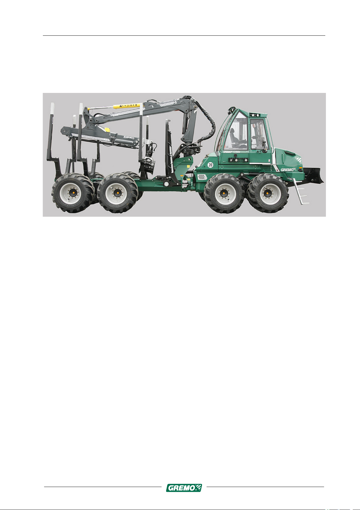
Fig. 1 Gremo 1250F/1450F
Gremo 1250F/1450F
• is a robust and versatile 12 to 14 tonne forwarder that
easily navigates all types of terrain. The forwarder is
designed and adapted for forwarding timber, the weight
of which does not exceed the machine's maximum load
capacity, from felling site in the forest to the roadside
stacking area.
• is driven by a Cummins QSB 6-cylinder, turbo-charged
6.7 litre diesel engine with intercooler and common rail
fuel system that complies with stage 3B environmental
requirements and is approved for running on
environmentally-friendly fossil-free diesel that complies
with the requirements in EN 15940, e.g. HVO diesel.
• is fitted with Gre-VT, a continual and variable
hydrostatic transmission with 2 speeds that are
controlled by GreControl. Full traction (18.4 tonnes) is
available from the start whatever program is run.
• has electric/hydraulic brakes. Four multi-disc brakes in
oil bath in the front and rear differentials.
• has a load-sensing hydraulic system with hydraulicallydriven variable fan with reversing option to blow out the
coolers controlled by GreControl; the oil is cleaned by a
return filter and a microfilter.
• has a 24 volt electrical system with dual 145 Ah
batteries.
4

Gremo 1250F/1450F Workshop manual 1 Introduction
1.4 Intended area of use
1.4 Intended area of use
The machine must only be used for what it has been
designed and adapted for, i.e. forwarding forest raw
materials, the weight of which does not exceed the
machine's maximum load capacity, from felling site in the
forest to the roadside stacking area. All other use is
prohibited.
It is not permitted to rebuild or modify the machine without
Gremo's approval.
It is not permitted to operate the machine on public roads if
it has not been adapted to comply with national road safety
rules.
1.4.1 Improper use
Do not under any circumstances use the machine for
anything it is not designed for, e.g.
The crane
• should never be used to lift loads greater than it was
designed to lift.
• should never be used to tow or push objects.
• should never be used to lift people.
The machine
• should never be used for anything other than it has
been designed for i.e. loading and unloading timber.
• should never be used if any safety feature is out of
order, e.g. if any safety sensor is disconnected.
• should never be used if a window is broken or with the
door open.
• should never be loaded with weights greater than it was
designed to handle.
• should never be parked on a slope, but must always be
parked on level ground to prevent the machine rolling
away or capsizing.
1.4.2 Prohibited operation
It is prohibited to operate the machine if:
• Protection and warning equipment is out of order or
disconnected.
• If brakes or steering system are faulty.
5

1 Introduction
1.5 Operator requirements
1.5 Operator requirements
Gremo 1250F/1450F Workshop manual
• If there are any unauthorised people or vehicles within
the machine's operating area.
• The machine can only be operated by operators with
permission from work supervisors and the necessary
knowledge.
• National laws and regulations relating to driving
licences, operator certificates, etc. must be complied
with at all times.
• Operators must be aware of and follow all local safety
rules.
• Operators must follow the manufacturer's instructions.
• Operators must read and understand the machine's
warning and information signs, as well as understand
and be able to use the machine's protection and
warning equipment.
1.6 Safety regulations
Each country has its own national and local safety
regulations, and it is the responsibility of both the owner
and the operator to know and follow these regulations. If
the recommendations in this Instruction Manual differ from
the national and local safety regulations, then the national
and local safety regulations take precedence over the
recommendations in this Instruction Manual.
During the design and testing of the machine, a great deal
of effort has been made to make the machine safe and
efficient. These efforts may be completely wasted if the
safety and maintenance regulations are not followed.
Accidents are usually caused by humans, not by the
machine. A well-maintained machine and a safety-aware
owner/operator is a profitable and safe combination.
A Gremo machine meets the requirements of the
Machinery Directive and the harmonised standards, plus
national requirements and provisions.
6

Gremo 1250F/1450F Workshop manual 1 Introduction
1.7 Warning symbols and information about risks
1.7 Warning symbols and information about
risks
The following warning symbols and signal words are used
throughout this manual and on stickers on the machine:
NOTICE
Read this important information carefully.
If a number of risks occur simultaneously, this Instruction
Manual shows the signal word (DANGER, WARNING,
CAUTION) corresponding to the greatest risk.
NOTE! indicates that attention should be given to
anything concerning safety of the surroundings or the
machine or other important information that may
facilitate understanding or performance of a particular
task.
You can prevent accidents by reading these paragraphs
with special care and always following the instructions.
Remember that your safety and the safety of others may
be affected. It is also the responsibility of the operator to
ensure that all warning stickers are in place on the
machine and are readable.
DANGER
Informs of a very serious hazard which, if not avoided,
may be fatal or cause serious bodily harm
WARNING
Informs of a very hazard which, if not avoided, may be
fatal or cause serious bodily harm.
CAUTION
Informs of a minor hazard which, if not avoided, may
cause minor bodily harm.
7

1 Introduction
1.8 Construction of the machine
1.8 Construction of the machine
1.9 Definitions
Gremo 1250F/1450F Workshop manual
NOTICE
This Instruction Manual is designed to be valid in several
market areas and for most factory-installed equipment.
Please ignore the paragraphs which are not valid for
your machine. We reserve the right to change and
improve the design whenever we find it necessary,
without undertaking to implement these changes on
products which have already been delivered. We also
reserve the right to change data and instructions for
maintenance, service, environment and safety without
further notice.
In this Instruction Manual, the concepts of ‘front’, ‘rear’,
‘right’ and ‘left’ on the machine are defined according to
the principal direction of travel on roads, i.e. the direction
the machine travels when it is steered using the steering
wheel.
Example: the serial number of the machine is punched on
the frame in the front end of the machine, to the right of the
engine compartment.
1.10 Environment
The interplay between human beings, machines and the
environment can be influenced, and is becoming
increasingly important. We have paid attention to this
during the design of the machine and the writing of this
manual, which has a section relating to this subject. By
following these instructions when you drive and maintain
your machine, you will show consideration for humans,
animals and nature in your environment.
8
Gremo 1250F/1450F Workshop manual 1 Introduction
1.11 Location of type plates and serial numbers
1.11 Location of type plates and serial
numbers
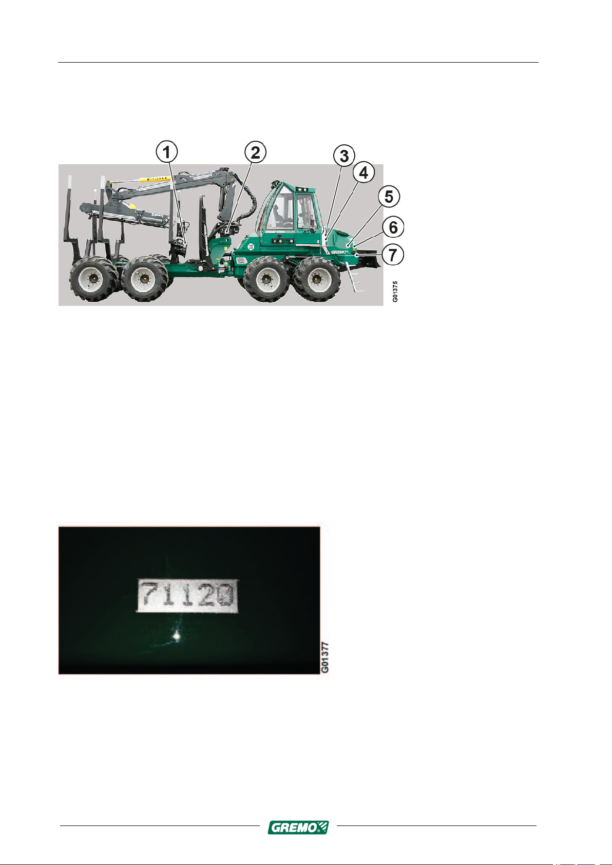
Fig. 2 Type plates and serial numbers
1. Type plate for the grapple
2. Type plate for the crane
3. Type plate for the cab
4. Type plate for the machine
5. Type plate for the diesel engine (on the rocker cover)
6. Type plate for the climate system on the right hand side of the radiator
7. The machine's serial number is punched on the front of the right-hand branch deflector.
1.11.1 Serial number
Fig. 3 Serial number
The machine's serial number is punched on the top of the
front of the right-hand branch deflector.
9
1 Introduction
1.11 Location of type plates and serial numbers
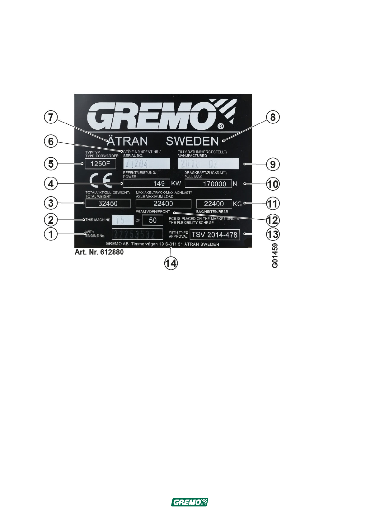
1.11.2 Type plate for the machine
The following details are shown on the machine's type
plate:
Gremo 1250F/1450F Workshop manual
1. Diesel engine’s serial number
2. Machine no. XX of XX
3. Machine's total weight
4. Diesel engine's power in KW
5. Machine model
6. Machine's serial number
7. Place of manufacture
Fig. 4 Type plate for the machine
8. Country of manufacture
9. Year and month of manufacture
10.Machine's traction in N
11. Maximum axle load, rear bogie in kg
12.Maximum axle load, front bogie in kg
13.Type approval according to:
14.Manufacturer's address
10

Gremo 1250F/1450F Workshop manual 1 Introduction
1.11 Location of type plates and serial numbers
1.11.3 Type plate for the cab
The following details are shown on the cab's type plate:
1. Approved according to:
2. Model/Type
3. Serial no.
4. Year of manufacture
5. Weight
1.11.4 Example of crane type plate
Fig. 5 Type plate for the cab
The following details are shown on the crane's type plate:
1. Model/Type
2. Serial no.
3. Weight
4. Year of manufacture
Fig. 6 Type plate for the crane
11

1 Introduction
1.11 Location of type plates and serial numbers
1.11.5 Example of grapple type plate
The following details are shown on the grapple's type
plate:
Fig. 7 Type plate for the grapple
1. Model
2. Serial no.
Gremo 1250F/1450F Workshop manual
3. Weight
4. Year of manufacture
1.11.6 Type plate for the diesel engine
The machine’s chassis number (engine type and number
are normally connected to the chassis number) must be
stated when ordering spare parts.
If the engine's type plate is not legible, the engine's serial
number can also be read from the engine block on top of
the lubricating oil cooler housing.
The injection pump is itemised from Gremo AB.
The following details are shown on the engine's type plate:
1. Engine serial number
2. Engine type
3. CPL number
4. Valve clearance tolerances
12
Fig. 8 Type plate for the diesel engine
5. Power output data
6. Ignition sequence
7. Important information

Gremo 1250F/1450F Workshop manual 2 Safety regulations
2.1 General
2 Safety regulations
2.1 General
Operators, mechanics and supervisors are obliged to
study and follow the safety regulations and advice given in
this chapter.
The machine is equipped with signs, and you should make
yourself familiar with the meaning and location of these
signs. Make sure that the signs are readable and replace
any damaged signs.
Furthermore you shall always follow the laws, statutes or
other national regulations concerning traffic safety and
occupational safety. Local traffic rules and local workplace
regulations must always be followed.
WARNING
The cab is not intended for passenger transport, which is
why it lacks a seat and seat belt for passengers. There is
a risk of fatal accident for passengers!
WARNING
The bogie lift can be used as a lifting aid during service
and repairs, but always prop up the machine.
WARNING
When you lift or prop up the machine or parts of the
machine, make sure that the equipment you use is
intended for this purpose, is appropriately dimensioned,
and cannot slip or tip over!
WARNING
Risk of serious crushing injury or fatal accident!
Always switch off the engine before releasing the cab to
tip it up.
Never go under a tipped-up cab unless it is propped up.
Ensure that the cab is propped up if you need to go
under it!
13
2 Safety regulations
2.1 General
Gremo 1250F/1450F Workshop manual
WARNING
Do not leave the cab without first placing the grapple/
crane safely on the ground or in the loading platform.
WARNING
During all work on the machine, remember the risk of
slipping. You should always use a safety helmet, safety
goggles, gloves, safety boots, breathing protection and
other necessary protective equipment when required.
CAUTION
Never leave the machine unattended with the engine
running or the ignition on.
Never leave the machine unattended with the ignition
key in the ignition lock.
CAUTION
Never operate the machine with loose tools, binders, etc.
in the cab, as these items may injure you if the machine
tips over or brakes suddenly.
Secure them properly.
CAUTION
During servicing, the engine and main power switch
must always be turned off. In some cases this also
applies to fire extinguishing and other electronic
equipment.
CAUTION
14
The manufacturer is not responsible for alterations to the
electrical system of the machine, if these do not
correspond to the original state. The function of the
machine’s safety system can be affected.
CAUTION
The machine may be operated and repaired only by
personnel who have undergone training approved by the
supplier.

Gremo 1250F/1450F Workshop manual 2 Safety regulations
2.1 General
NOTICE
For your mobile phone and other portable
communication equipment you should always use
externally mounted aerials in order to prevent
interference with the computers of the machine.
NOTICE
Never use the main power switch to turn off the machine
as this can cause damage to the machine!
NOTICE
Off-road driving requires a lot of experience before you
master the machine. Because of this, you should take it
easy until you are familiar with the limitations of the
machine.
NOTICE
Always bear in mind the danger of fire, and keep the
machine clean. Check the fire extinguishing equipment
as in the instructions.
15
2 Safety regulations
2.2 Clothing
2.2 Clothing
Gremo 1250F/1450F Workshop manual
To prevent clothes getting caught or stuck, clothing should
be intact and tight fitting. Do not use loose garments such
as ties or scarves because they can get caught in levers
and rotating or protruding parts.
Do not wear jewellery as it can conduct electricity or get
stuck in moving parts.
Long hair should be tied back properly as it can easily get
caught in moving parts. Be careful when working with
welders or open flames as hair is flammable.
Always wear gloves, safety footwear, safety goggles, a
safety helmet, ear defenders and other necessary safety
equipment when required.
2.3 Seat belt
Fig. 9 Seat belt
Always use the seat belt.
Replace a damaged or worn seat belt immediately. Order
from you nearest Gremo service dealer or from Gremo AB
using spare part number 92900100.
Before you start operating the machine, check that there is
no one standing close to it. Risk distance 20 m.
Never drive with an open door. The operator’s cab is not a
safety cab if the door is open.
16
Gremo 1250F/1450F Workshop manual 2 Safety regulations
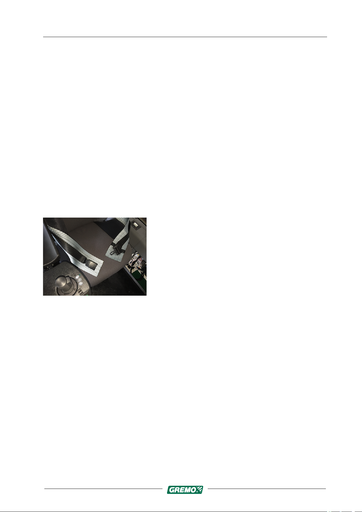
2.4 Emergency stop
2.4 Emergency stop
Check the emergency stop function daily. The emergency
stop is the red switch with the yellow plate.
The external emergency stop is located on the right-hand
ascent into the machine, and the cab emergency stop is on
the left-hand 'B' column. When you push the emergency
stop, the diesel engine stops and the brakes are applied.
Fig. 10 External emergency stop
Fig. 11 Cab emergency stop
17
2 Safety regulations
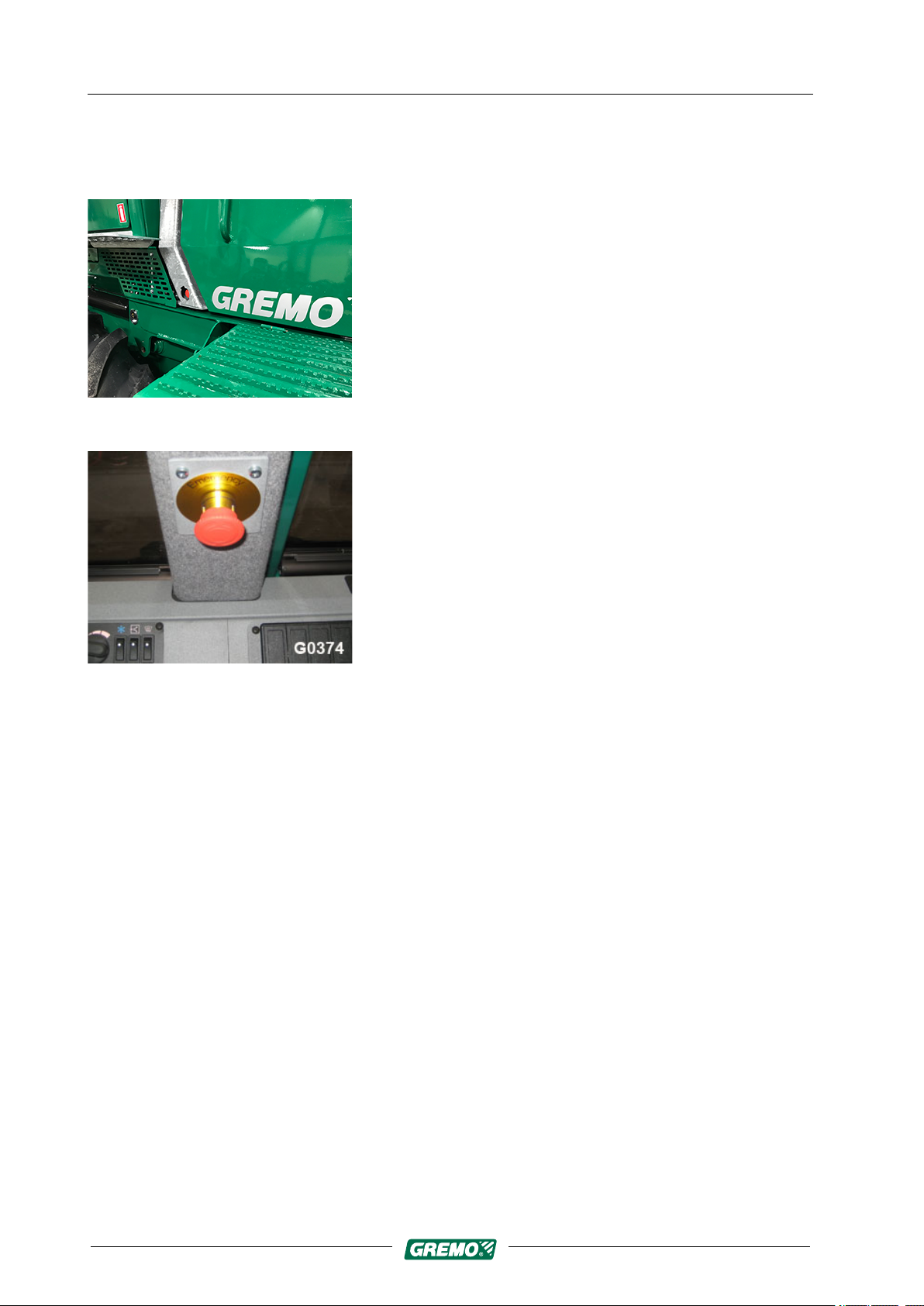
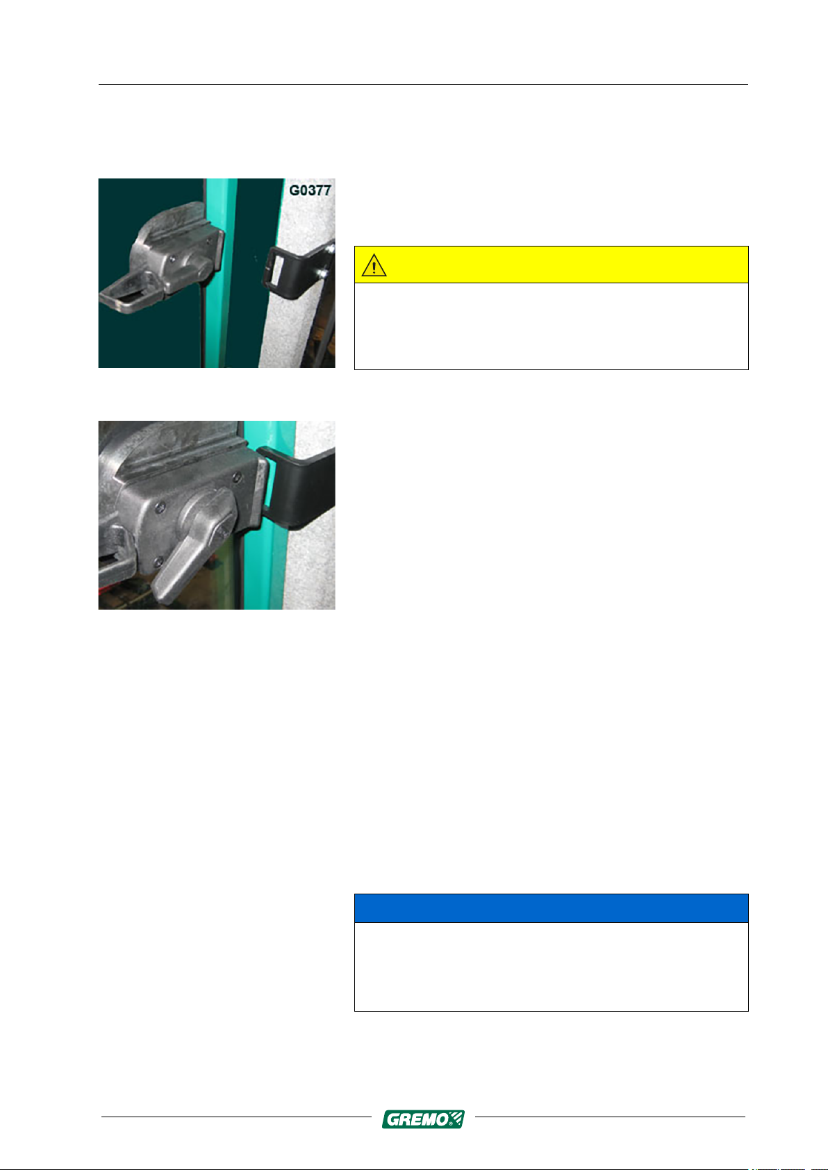
2.5 Emergency exit
2.5 Emergency exit
Fig. 12 Handle side window
Gremo 1250F/1450F Workshop manual
The left-hand side window acts as the emergency exit. To
open the window, grip the latch handle and turn it upwards
until the latch is released. The window can now be opened
outwards.
CAUTION
Note that the side window must always be unlocked
when the machine is operating, to ensure that the
operator can be rescued from outside if the machine tips
over.
Fig. 13 Opened side window
2.6 Emergency alarm
2.7 Articulated joint lock
Emergency alarm equipment, e.g. mobile phone or other
portable communication equipment, must be available.
When you work outside the machine, always take your
mobile phone or other means of communication with you.
NOTICE
The articulated joint lock and the brakes are released
when the machine starts pulling at about 1,000 rpm. If
the crane is slewed at this time, the machine may tip
unexpectedly.
18
The articulated joint lock consists of two hydraulic
cylinders which are automatically blocked and lock the
mid-section when the machine is stopped. The articulated
Gremo 1250F/1450F Workshop manual 2 Safety regulations
2.8 Boarding the machine
joint lock is released when you ”rev” with the accelerator
pedal. For settings, see GreControl in the User Manual.
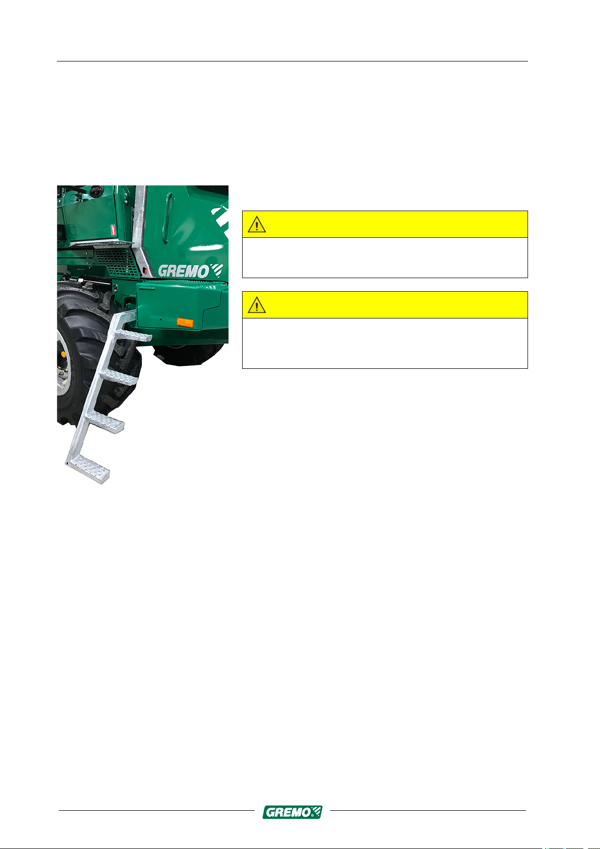
2.8 Boarding the machine
Use the ladder, and hold on to the handle on the bonnet,
the handle on the cab column and the door handle.
CAUTION
Risk of slipping – steps, platforms and chains can be
very slippery in cold weather conditions!
CAUTION
Fig. 14 Ascent
Always descend the ladder facing the machine. This way
you can see and grip the handles. Never jump from the
machine.
19

2 Safety regulations
2.9 Inspection of parking brake
2.9 Inspection of parking brake
Gremo 1250F/1450F Workshop manual
The parking brake is a safety detail and its working order
should be checked.
• Place the fully-loaded machine on a slight slope, 10-12
degrees, or a climb of 2 m per 10 m with free rolling
movement with no obstacles.
• Stop the machine.
• Engage parking brake.
• Switch off the engine.
• The machine should now be standing completely still
without rolling.
• Start the engine and turn the machine around. Repeat
the procedure with the machine facing in the other
direction.
20
Gremo 1250F/1450F Workshop manual 2 Safety regulations
2.9 Inspection of parking brake
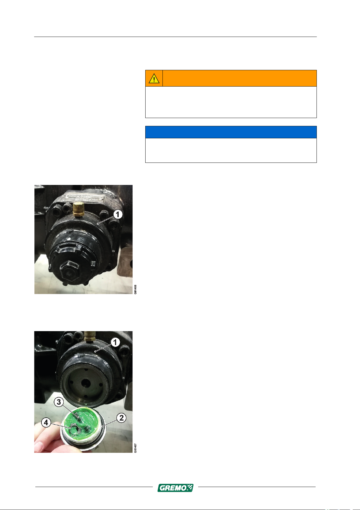
2.9.1 Manual release of parking brake
WARNING
Before starting the work of manually releasing the
parking brake, ensure that the machine's wheels are
locked to prevent it from rolling.
NOTICE
If the parking brake does not release, it may be
necessary to manually release it to move the machine.
1. Parking brake cylinder
The machine's parking brake can be manually released
if a pressure drop in the hydraulic system prevents
hydraulic release.
Fig. 15
Fig. 16
2. Remove the cover plate (2).
The parking brake (1) is released using a threaded stud
(3) and washer/counter-locking nut (4) found in the
cover plate (2).
21
2 Safety regulations
2.9 Inspection of parking brake
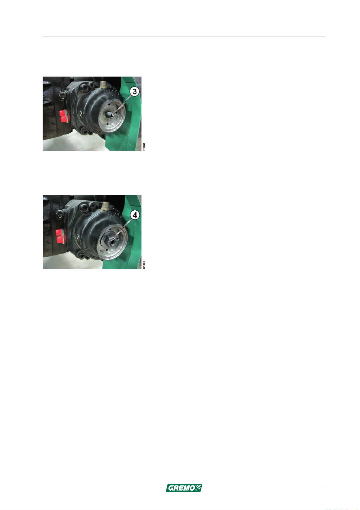
Fig. 17
Gremo 1250F/1450F Workshop manual
3. Screw the threaded stud (3) all the way in through the
hole in the brake cylinder and tighten until it stops.
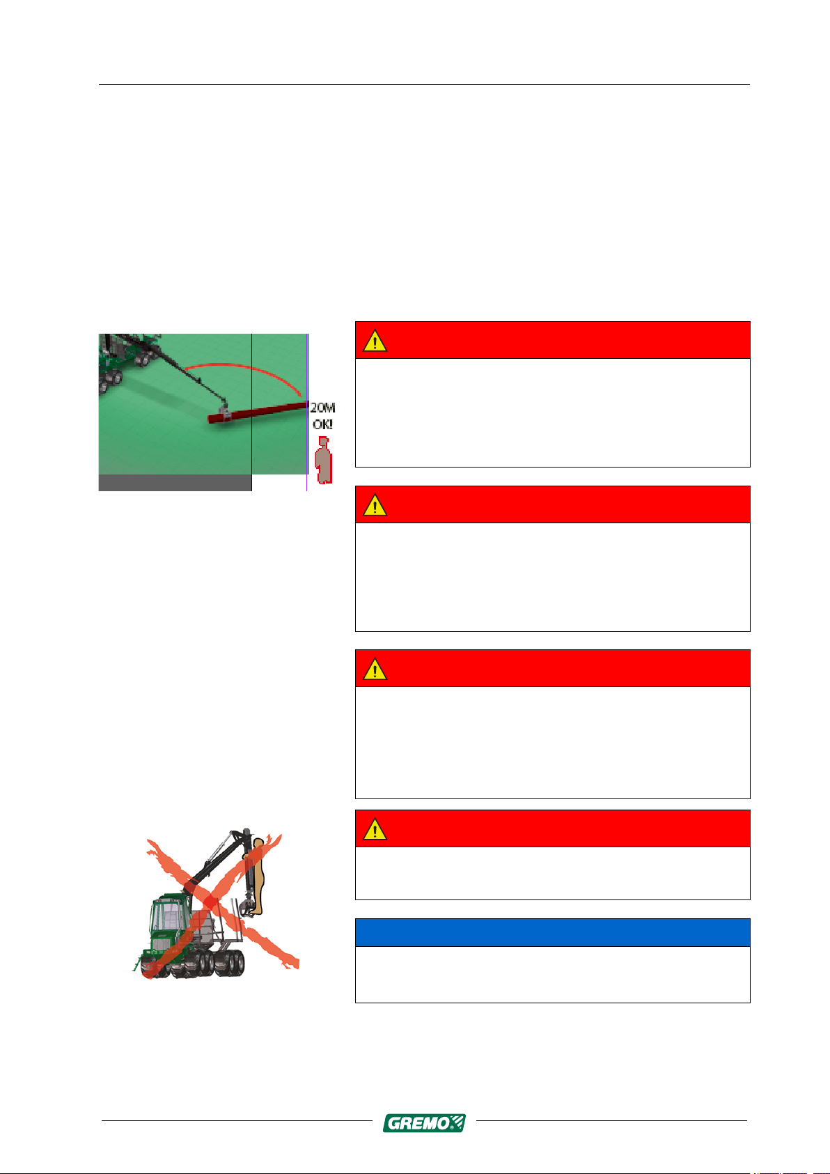
4. Fit the washer and counter-locking nut (4) and tighten
the nut to release the spring force in the brake cylinder.
Fig. 18
5. Repeat for all four brake cylinders to release the
parking brake.
Reset the parking brakes by loosening and removing the
counter-locking nuts, washers and threaded studs again,
and put them back in the cover plate.
22

Gremo 1250F/1450F Workshop manual 2 Safety regulations
2.10 Driving
2.10 Driving
The working speed is set between 1,200-1,500 rpm in the
Control System GreControl/IQAN monitor.
As soon as you start to use the crane levers the working
speed is activated, and when you release the crane levers
the revs reduce to an increased idle after the time delay
selected in GreControl. This occurs when the seat is facing
backwards towards the crane/gate.
Driving on public roads
When driving on public roads with other traffic, the steering
wheel must always be used, and the terrain driving
function must be turned off.
Driving speed
A Gremo 1050F is designed to manage a maximum load
of 10,500 kg, even on difficult terrain. Off-road driving
causes large dynamic forces on the machine. The
machine’s own weight, plus the load, increases the stress
in its construction if driven carelessly over difficult terrain.
By driving gently, with feeling and understanding, you can
avoid costly repairs and downtime.
Fig. 19 Overload
Uphill
When driving uphill, the centre of gravity of the payload is
shifted backwards, exerting a lifting force on the front
carriage. If the machine is angled severely in this situation,
it can tip over..
Downhill
The load’s centre of gravity is moved forward when driving
down a slope, and exerts a pushing force on the engine. If
the machine is angled severely in this situation, it can tip
over..
NOTICE
Never load over the top of the gate!
Overloading leads to worse stability, and during downhill
driving the timber may slide over the gate and damage
the machine.
23
2 Safety regulations
2.11 Crane operation
2.11 Crane operation
Gremo 1250F/1450F Workshop manual
Read the instructions carefully before you operate the
crane for the first time. See the sub-supplier's
documentation.
There is a considerable risk of accidents if you start
without being sufficiently familiar with the design, function
and use of the crane. Ensure that you follow the applicable
laws and regulations and that you have full view of the
whole working area.
DANGER
Standing under the crane may cause danger to life!
Ensure that there are no unauthorised persons within
the working area of the crane.
Fig. 20 Crane danger area
A risk distance of at least 20 m must be observed!
DANGER
Never work underneath electric power lines.
There is a large risk that the crane touches the power
lines, and this may cause a fatal accident!
A risk distance of at least 10 m must be observed!
DANGER
If the machine comes in contact with overhead power
lines. Remain in your seat and call for assistance!
Danger!
Remain in your seat. Wait for assistance!
DANGER
Fig. 21 lifting people with crane
24
Never use the crane to lift people. Risk of injury or fatal
accident!
NOTICE
Do not move the vehicle when the crane is carrying a
load, or when the crane boom is slewed laterally.

Gremo 1250F/1450F Workshop manual 2 Safety regulations
2.11 Crane operation
NOTICE
Observe the lifting capacity limits on the load sign. Never
overload.
NOTICE
Never run the hydraulic cylinders towards the end stops
at full speed!
Risk of damage to the machine
NOTICE
The articulated joint lock and the brakes are released
when the machine starts pulling at about 1,000 rpm. If
the crane is slewed at this time, the machine may tip
unexpectedly.
Fig. 22 Parking the crane
NOTICE
During transportation the crane should be put on the
load, strapped to the timber. Observe all safety
precautions, as there may be power or telephone lines at
unexpectedly low heights.
NOTICE
Use the reach to pull the timber towards you, and then
lift.
NOTICE
It is prohibited to use the crane for towing timber or other
items.
25

2 Safety regulations
2.12 Parking/storage
2.12 Parking/storage
Gremo 1250F/1450F Workshop manual
• For safety reasons, park the machine on a level surface
when it is not to be used.
• Let the machine idle for a minute or so before turning off
the engine.
• The ladder is folded down when the switch for the
parking brake is put into parking mode.
• Stop the engine.
• Turn off the main power supply.
• Lock the machine!!
Before leaving the machine, always ensure that:
• The machine is parked on a flat surface and not on a
slope.
• The parking brake is engaged.
• The machine is completely still without using the
hydraulics to do so.
• The engine is turned off.
• The main power switch is turned off.
• The machine is locked and the keys are removed from
the machine.
WARNING
For safety reasons, do not park the machine on a slope.
There is the risk that the machine will start to move or tip
over.
26
 Loading...