


E2 6. 0. 0. 6B -0 2 Blatt 1 von 2
Bedienungsanleitung für Digital-Einbau-Thermometer
GTH 2448 / 1
Technische Daten:
Meßbereich: -50 ... +1150 °C
Auflösung: 1°C
Fühleranschluß: NiCr-Ni, Fühler ist nicht im Lieferumfang enthalten.
Genauigkeit: < 1% ±1 Digit (von -20 bis +550°C bzw. 920 bis 1150°C); <1.5% ±1 Digit von 550...920°C.
Theoretische Abweichungswerte: siehe beiligende Korrekturtabelle
Anzeige: 10 mm hohe, 3½-stellige rote LED-Anzeige
Abtastrate: ca. 3 Messungen/sec.
Nenntemperatur: 25°C
Arbeitstemperatur: 0 bis 50°C
Relative Luftfeuchtigkeit: 5 bis 95 % r.F. (nicht betauend)
Lagertemperatur: -20 bis 85°C
Spannungsversorgung: 12 V DC (8 - 20 V DC) oder 24 V DC (18 - 29 V DC) bzw.
12 V AC (8 - 20 V AC) oder 24 V AC (18 - 27 V AC) (einstellbar über Lötbrücke)
Stromverbrauch: max. 20 mA
Gehäuse: glasfaserverstärktes Noryl, Frontscheibe PC.
Abmessungen: 24 x 48 mm (H x B) (Frontrahmenmaß)
Einbautiefe: ca. 65 mm (inkl. Schraub-/Steckklemmen)
Panelbefestigung: mit VA-Federklammer, mögliche Paneldicken: von 1 bis ca. 10 mm
Schalttafelausschnitt: 21.7
+0.5
Anschlußklemmen: 4-polige Schraub-/Steckklemme für Leiterquerschnitte von 0.14 bis 1.5 mm²
Störfestigkeit (EMV): Das Gerät ist geprüft nach EN50081-1 und EN50082-1
zusätzlicher Fehler: <1%
Schutzklasse: frontseitig IP54 (mit optionellen O-Ringen IP65).
x 45
+0.5
mm (H x B).
Temperatur Anzeige
-50 -46
-40 -37
-30 -28
-20 -19
-10 -10
00
10 10
20 20
30 29
40 39
50 49
60 59
70 70
80 80
90 90
100 100
110 110
120 120
130 130
140 140
150 150
Temperatur Anzeige
160 160
170 169
180 179
190 189
200 198
210 208
220 218
230 228
240 238
250 248
260 258
270 268
280 278
290 288
300 298
310 308
320 318
330 328
340 339
350 349
360 359
K o r r e k t u r t a b e l l e :
Temperatur Anzeige
370 369
380 379
390 390
400 400
410 410
420 421
430 431
440 441
450 452
460 462
470 472
480 483
490 493
500 504
510 514
520 524
530 535
540 545
550 556
560 566
570 576
Temperatur Anzeige
580 587
590 597
600 607
610 618
620 628
630 639
640 649
650 659
660 670
670 680
680 690
690 700
700 711
710 721
720 731
730 741
740 751
750 762
760 772
770 782
780 792
Temperatur Anzeige
790 802
800 812
810 822
820 832
830 842
840 852
850 862
860 871
870 881
880 891
890 901
900 911
910 920
920 930
930 940
940 949
950 959
960 969
970 978
980 988
990 997
Temperatur Anzeige
1000 1007
1010 1016
1020 1026
1030 1035
1040 1045
1050 1054
1060 1063
1070 1073
1080 1082
1090 1091
1100 1100
1110 1110
1120 1119
1130 1128
1140 1137
1150 1146
1160 1155
1170 1164
1180 1173
E2 6. 0. 0. 6B -0 2 Blatt 2 von 2
+Uv
GND
S+
S-
12VDC
(8...20VDC)
24VDC
(18...29VDC)
Elektrischer Anschluß:
Die Anschlüsse des GTH 2448 / 1 befinden sich auf der Rückseite des Gerätes.
Der Anschluß erfolgt über Schraub-/Steckklemmen.
Schraub-/Steckklemmen sind grundsätzlich im losen Zustand zu montieren und anschließend erst aufzustecken.
Bei Montage an gesteckten Klemmen können Lötaugen losgerissen werden. Bitte verwenden Sie einen passenden
Schraubenzieher und ziehen Sie die Schrauben nicht mit Gewalt an.
Versorgungsspannung: 12 V DC/AC bzw. 24 V DC/AC
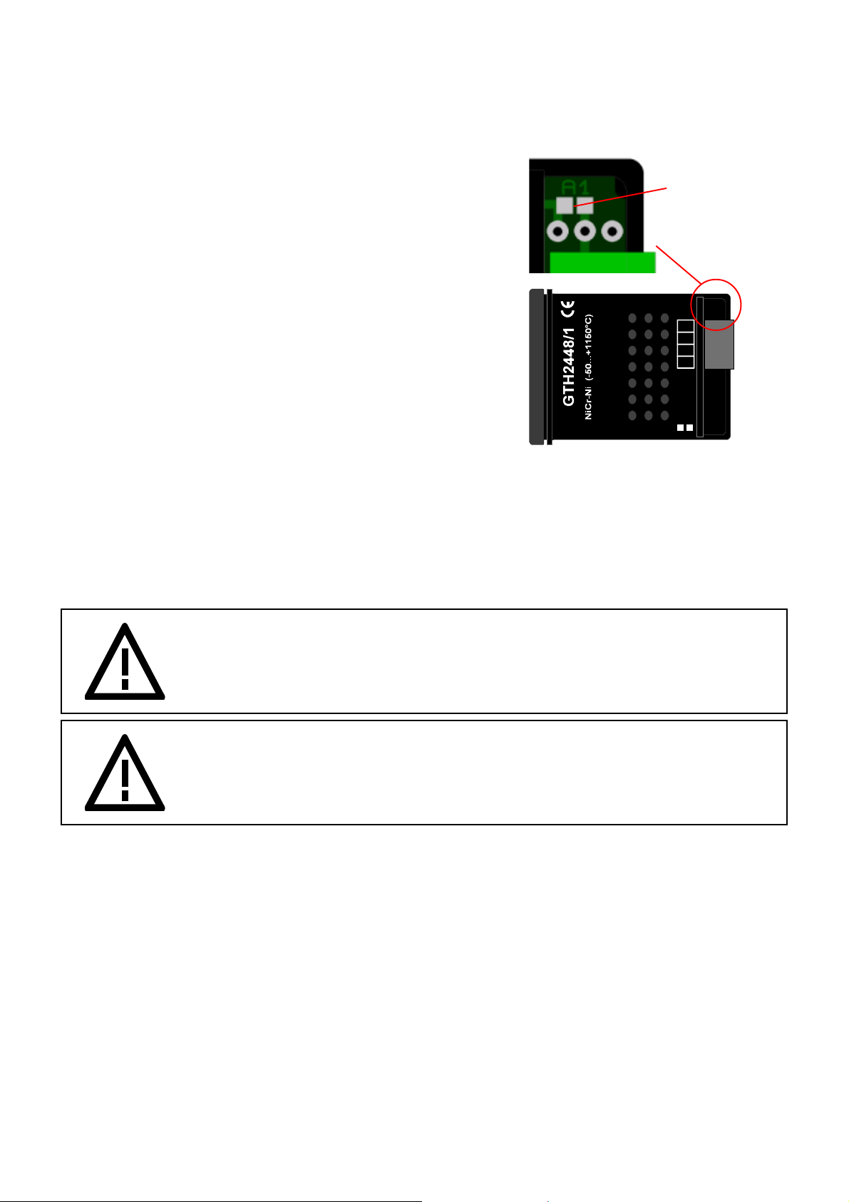
Lötbrücke A1
Die Auswahl der Versorgungsspannung erfolgt über eine Lötbrücke
neben der Anschlußklemme.
Bitte vergewissern Sie sich, daß die Versorgungsspannung mit dem
eingestellten Spannungsbereich übereinstimmt
Brücke "A1" offen: 24 V ( 18 - 29 V DC o. 18 - 27V AC )
Brücke "A1" geschlossen: 12 V ( 8 - 20 V DC o. 8 - 20 V AC)
Fühleranschluß: NiCr-Ni (Typ K)
Der Anschluß bzw. die Inbetriebnahme darf nur durch fachlich
qualifizierte Personen erfolgen. Bei falschem Anschluß kann das
Gerät zerstört werden -- kein Garantieanspruch
Sicherheitsbestimmungen
Beachten Sie grundsätzlich folgende Punkte, um eine Gefährdung des Bedieners auszuschließen:
a) Setzen Sie das Gerät bei erkennbaren Beschädigungen oder Funktionsstörungen sofort außer Betrieb.
b) Trennen Sie das Gerät vor dem Öffnen von der Versorgungsspannung. Achten Sie bei der Montage von Gerät und Anschlüs-
sen darauf, daß alle Teile gegen direktes Berühren geschützt sind.
c) Beachten Sie die üblichen Vorschriften und Sicherheitsbestimmungen für Elektro-, Schwach- und Starkstromanlagen,
insbesondere die landesüblichen Sicherheitsbestimmungen (z.B. VDE 0100).
d) Konzipieren Sie die Beschaltung besonders sorgfältig beim Anschluß an andere Geräte. Unter Umständen können interne
Verbindungen in Fremdgeräten zu nicht erlaubten Spannungspotentialen führen.
Warnung: Beim Betrieb elektrischer Geräte stehen zwangsläufig Teile dieser Geräte unter gefährlicher
Spannung. Bei Nichtbeachtung der Warnhinweise können deshalb schwere Körperverletzungen oder Sachschäden auftreten. Nur entsprechend qualifiziertes Personal sollte an
diesem Gerät arbeiten. Der einwandfreie und sichere Betrieb dieses Gerätes setzt sachgemäßen Transport, fachgerechte Lagerung, Aufstellung und Montage sowie sorgfältige
Bedienung und Instandhaltung voraus.
Warnung:
Benützen Sie dieses Produkt nicht in Sicherheits- oder in Notaus-Einrichtungen oder in Anwendungen wo ein
Fehlverhalten des Gerätes die Verletzung von Personen oder materielle Schäden zur Folge haben kann.
Wird dieser Hinweis nicht beachtet so kann dies zu Verletzung oder zum Tod von Personen sowie zu
materiellen Schäden führen.
Qualifiziertes Personal
sind Personen, die mit Aufstellung, Montage, Inbetriebnahme und Betrieb des Produktes vertraut sind und über die
ihrer Tätigkeit entsprechende Qualifikation verfügen. Zum Beispiel:
! Ausbildung oder Unterweisung bzw. Berechtigung, Stromkreise und Geräte/Systeme gemäß den Standards der Sicherheits-
technik ein- und auszuschalten, freizuschalten, zu erden und zu kennzeichnen.
! Ausbildung oder Unterweisung gemäß dem Standard der Sicherheitstechnik in Pflege und Gebrauch angemessener
Sicherheitsausrüstung.
! Schulung in Erster Hilfe.
Zubehör:
GNG220/1-12V Netzgerät für GTH2448 Eingang: 230V AC; Ausgang: 12V DC stabilisiert, max. 40mA
IP65 SET O-Ringe O-Ringe für frontseitige Schutzklasse IP65 (2 Stück)
GTF 300 - AdH Drahtfühler -65 ... +300°C Universalfühler für Messungen in Flüssigkeiten, Gasen und an
GMF 250 - AdH Oberflächenfühler -65 ... +250°C Magnetfühler, selbsthaftend auf magnetischen Werkstoffen
bei Bestellung von Standard-Fühler (im Katalog mit NiCr-Ni-Stecker angeboten), ist die Endung "- AdH" o. ohne Stecker anzugeben!
(kleine Auswahl - komplette Übersicht siehe Katalog)
kleinen Oberflächen (Fühlerlänge ca. 1m).
(Fühler mit ca. 1m Kabel)

E26.0.01.6C-02 page 1 of 2
Operating Manual for Digital Thermometer
GTH 2448 / 1
Specification:
Measuring range: -50 ... +1150 °C
Resolution: 1°C
Probe connection: NiCr-Ni, (probe not included in scope of supply)
Accuracy: < 1% ±1 Digit (from -20 to +550°C and 920 to 1150°C); <1.5% ±1 Digit from 550...920°C.
For more detailed values please refer to att. correction table.
Display: 3½-digit, red LED-display, 10 mm high
Scan rate: approx. 3 measurements/sec.
Nominal temperature: 25°C
Working temperature: 0 to 50°C
Relative humidity: 5 to 95 % r.h. (non-condensing)
Storage temperature: -20 to 85°C
Voltage supply: 12 V DC (8 - 20 V DC) or 24 V DC (18 - 29 V DC) resp.
12 V AC (8 - 20 V AC) or 24 V AC (18 - 27 V AC) (to be set via soldering jumper)
Power consumption: max. 20 mA
Housing: glass fibre reinforced Noryl, front screen PC.
Dimensions: 24 x 48 mm (H x W) (dimensions of front frame)
Mounting depth: approx. 65 mm (incl. screw-type/plug-in terminals)
Panel mounting: by means of VA- elastic spike, allowed panel thickness: from 1 to approx. 10 mm
Panel cut-out: 21.7
+0.5
Connection terminals: 4-pin screw-type/plug-in terminals for wire dias ranging from 0.14 to 1.5 mm²
EMC: Device has been tested according to EN50081-1 and EN50082-2
additional fault: <1%
IP rating: front IP54 (with optional O-rings IP65).
x 45
+0.5
mm (H x W).
Temperature Display
-50 -46
-40 -37
-30 -28
-20 -19
-10 -10
00
10 10
20 20
30 29
40 39
50 49
60 59
70 70
80 80
90 90
100 100
110 110
120 120
130 130
140 140
150 150
Temperature Display
160 160
170 169
180 179
190 189
200 198
210 208
220 218
230 228
240 238
250 248
260 258
270 268
280 278
290 288
300 298
310 308
320 318
330 328
340 339
350 349
360 359
C o r r e c t i o n t a b l e :
Temperature Display
370 369
380 379
390 390
400 400
410 410
420 421
430 431
440 441
450 452
460 462
470 472
480 483
490 493
500 504
510 514
520 524
530 535
540 545
550 556
560 566
570 576
Temperature Display
580 587
590 597
600 607
610 618
620 628
630 639
640 649
650 659
660 670
670 680
680 690
690 700
700 711
710 721
720 731
730 741
740 751
750 762
760 772
770 782
780 792
Temperature Display
790 802
800 812
810 822
820 832
830 842
840 852
850 862
860 871
870 881
880 891
890 901
900 911
910 920
920 930
930 940
940 949
950 959
960 969
970 978
980 988
990 997
Temperature Display
1000 1007
1010 1016
1020 1026
1030 1035
1040 1045
1050 1054
1060 1063
1070 1073
1080 1082
1090 1091
1100 1100
1110 1110
1120 1119
1130 1128
1140 1137
1150 1146
1160 1155
1170 1164
1180 1173

E26.0.01.6C-02 page 2 of 2
+Uv
GND
S+
S-
12VDC
(8...20VDC)
24VDC
(18...29VDC)
Electric connection:
Electric connections for the GTH 2448 / 1 are located at the back of the device.
Connection is made via screw-type/plug-in terminals (max. terminal range 1,5mm²).
Make it a rule to always mount screw-type/plug-in terminals while they are still loose and connect only later.
If terminals are mounted after connection there is a risk that soldering eyes may come loose. Please use suitable
screw-driver and do not tighten screws by force.
Supply voltage: 12 V DC/AC or 24 V DC/AC
Terminal assignment: +Uv = supply voltage +
soldering jumper A1
GND = supply voltage -
Please make sure to check if supply voltage and voltage range set
conform to each other.
Use the soldering jumper next to the connection terminal to select
supply voltage:
Jumper "A1" open: 24 V ( 18 - 29 V DC or 18 - 27 V AC)
Jumper "A1" closed: 12 V ( 8 - 20 V DC or 8 - 20 V AC)
Probe connection: NiCr-Ni (type K)
Both the connection and commissioning of the device must only be carried
out by skilled personnel. In case of a wrong connection, the device may be
destroyed - no warranty claims can be accepted !
Safety regulations
Make it a rule to always observe the following points to exclude any risk whatsoever for the operator.
a) In case of any obvious damage and/or functional problems disconnect device immediately
b) Prior to opening it, disconnect device and supply voltage source. Make sure that all parts of the device are protected against
direct touching when mounting the device and setting its connections.
c) Please always adhere to the standard safety regulations for electric devices, power systems and light-current installations,
and make sure that your national safety regulations (e.g. VDE 0100) are observed.
d) If device is to be connected to other devices (e.g. via serial interface) the circuitry has to be designed most carefully. Internal
connection in third party devices may result in not-permissible voltages.
Warning: When operating electric devices parts of these devices will, as a matter of course, be live.
Unless the warnings are observed severe damage to life and limb or to property may be the
result. Make sure that only skilled personnel is working with this device. Trouble-free
operation of this device can only be guaranteed if it is properly transported and stored.
Carefull installation, mounting, operation and maintenance are vital factors for the safe
operation of this device.
Warning:
Do not use these product as safety or emergency stop devices, or in any other application where
failure of the product could result in personal injury or material damage.
Failure to comply with these instructions could result in death or serious injury and material damage.
Skilled personnel
These are persons who are familiar with the installation, mounting, commissioning and the operation of the product and have
acquired a qualification for their job:
! Training or instructions or qualification to switch on/off, isolate, ground and apply markings to circuits and devices/systems
in accordance with the latest state of the art standards of safety technology.
! Training or instructions regarding the proper care and use of suitable safety equipment in accordance with the latest state of
the art standards of safety technology.
! First aid training.
Accessories:
GNG220/1-12V power supply (230VAC) for GIA2448 input: 230V AC; output: 12V DC stabilised, max. 40mA
IP65 SET O-rings O-rings for IP rating IP65 at the front (2 pcs.)
GTF 300 - AdH Wire probe -65 ... +300°C Probe for quick-response measurements in liquids, gases and for
GMF 250 - AdH Surface probe -65 ... +250°C Magnetic surface probe, sticks of magnetic materials
When ordering standard probes (offered in catalogue with NiCr-Ni-plug), append "- AdH" or "no plug" to the type name!
(small selection - for our complete accessories refer to our catalogue)
small surfaces (probe lenght approx. 1m).
(probe with approx. 1m cable)
 Loading...