

Page 1
H60.0.12.6C-09
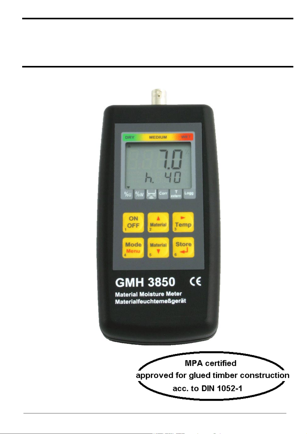
Operating Manual
Resistive Material Moisture Measuring
GMH 3850 as of version 1.5
GREISINGER electronic GmbH Hans-Sachs-Str. 26 Tel.: +49 9402 / 9383-0 http://www.greisinger.de
D-93128 Regenstauf Fax: +49 9402 / 9383-33 eMail: info@greisinger.de
Page 2

H60.0.12.6C-09 Operating Manual GMH3850 page 2 of 20
Contents
1 IN GENERAL.............................................................................................................................................................................3
1.1 S
1.2 O
1.3 D
1.4 C
1.5 D
1.6 P
AFETY INSTRUCTIONS .........................................................................................................................................................3
PERATING AND MAINTENANCE ..........................................................................................................................................3
ISPOSAL NOTICE .................................................................................................................................................................3
ONNECTIONS.......................................................................................................................................................................4
ISPLAY ELEMENTS ..............................................................................................................................................................4
USHBUTTONS ......................................................................................................................................................................4
2 DEVICE CONFIGURATION...................................................................................................................................................5
3 SOME BASICS OF PRECISION MATERIAL MOISTURE MEASURING ......................................................................6
3.1 M
3.2 S
3.3 A
3.4 A
3.5 M
3.6 M
OISTURE CONTENT U AND WET-BASIS MOISTURE CONTENT W ..........................................................................................6
PECIAL FEATURES OF THE DEVICE........................................................................................................................................6
UTOMATIC TEMPERATURE-COMPENSATION ('ATC').............................................................................................................6
UTO-HOLD FUNCTION.........................................................................................................................................................7
EASURING IN WOOD: MEASURING WITH TWO MEASURING-PIKES ....................................................................................7
EASURING OTHER MATERIALS ...........................................................................................................................................7
3.6.1 ‘Hard‘ Materials (concrete or similar): Measuring with brush-type probes (GBSL91 or GBSK91).............................7
3.6.2 ‘Soft‘ Materials (polystyrene or similar): Measuring with Measuring-pikes or -pins (GMS 300/91) ...........................7
3.6.3 Measuring bulk cargo, bales and other special measures ...........................................................................................8
3.7 M
EASURING OF MATERIALS, HAVING NO CHARACTERISTIC CURVES STORED.........................................................................8
4 HINTS FOR THE SPECIAL FUNCTIONS ............................................................................................................................8
4.1 M
4.2 P
4.3 I
OISTURE ESTIMATION ('WET' - 'MEDIUM' - 'DRY') .....................................................................................................8
RE-SELECTION OF FAVOURITE MATERIALS ('SORT') .............................................................................................................8
NDIVIDUALLY PROGRAMMABLE CHARACTERISTIC CURVES.................................................................................................8
5 OPERATION OF LOGGER.....................................................................................................................................................9
5.1 „F
5.2 „F
UNC-STOR“: STORING SINGLE MEASUREMENTS................................................................................................................9
UNC-CYCL“: AUTOMATIC RECORDING WITH SELECTABLE LOGGER-CYCLE-TIME ........................................................10
6 OUTPUT...................................................................................................................................................................................11
6.1 I
6.2 A
NTERFACE - BASE ADDRESS ('ADR.') .................................................................................................................................11
NALOGUE OUTPUT – SCALING WITH DAC.0 AND DAC.1 .................................................................................................11
7 FAULT AND SYSTEM MESSAGES.....................................................................................................................................12
8 APPLICATION IN THE GLUED TIMBER CONSTRUCTION ACC. TO DIN 1052-1 (MPA CERTIFIED) .............12
9 INSPECTION OF THE ACCURACY / ADJUSTMENT SERVICES ................................................................................12
10 SPECIFICATION................................................................................................................................................................13
APPENDIX A: SORTS OF WOOD ...............................................................................................................................................14
APPENDIX B: ADDITIONAL MATERIALS ..............................................................................................................................19
Page 3

H60.0.12.6C-09 Operating Manual GMH3850 page 3 of 20
1 In General
1.1 Safety Instructions
This device has been designed and tested in accordance to the safety regulations for electronic devices.
However, its trouble-free operation and reliability cannot be guaranteed unless the standard safety measures and
special safety advises given in this manual will be adhered to when using it.
1. Trouble-free operation and reliability of the device can only be guaranteed if it is not subjected to any other climatic
conditions than those stated under “Specification”.
2. Transporting the device from a cold to a warm environment condensation may result in a failure of the function. In
such a case make sure the device temperature has adjusted to the ambient temperature before trying a new startup.
3. The circuitry has to be designed most carefully if the device should be connected to other devices. Internal
connection in third party devices (e.g. connection GND and earth) may result in not-permissible voltages impairing
or destroying the device or another device connected.
4. Warning: Operating the device with a defective mains power supply (e.g. short circuit from mains voltage to output
voltage) may result in hazardous voltages at the device (e.g. at sensor socket)
5. Whenever there may be a risk whatsoever involved in running it, the device has to be switched off immediately and
to be marked accordingly to avoid re-starting. Operator safety may be a risk if:
- there is visible damage to the device
- the device is not working as specified
- the device has been stored under unsuitable conditions for a longer time
In case of doubt, please return device to manufacturer for repair or maintenance.
6. Warning: Do not use these product as safety or emergency stop device, or in any other application where failure of
the product could result in personal injury or material damage.
Failure to comply with these instructions could result in death or serious injury and material damage.
7. Risk of injury! The used measuring heads are very sharp, use thoroughly during your measuring to eliminate a
possible risk of injury.
1.2 Operating And Maintenance
• Battery Operation
The battery has been used up and needs to be replaced, if and „bAt“ are shown in lower display. The device
will, however, continue operating correctly for a certain time.
The battery has been completely used up, if ´bAt´ is shown in the upper display.
The battery has to be removed, when storing device above 50°C.
Hint: We recommend to remove the battery if device is not used for a longer period of time! Risk of Leakage
• Mains Operation
Attention: When using a power supply unit please note that operating voltage has to be 10.5 to 12 V DC. Do not
apply over voltage!! Simple 12V-power supplies often have excessive no-load voltage. We, therefore, recommend
using regulated voltage power supplies. Trouble-free operation is guaranteed by our power supply GNG10/3000.
Prior to connecting the plug power supply with the mains supply make sure that the operating voltage stated at the
power supply is identical to the mains voltage.
• Treat device and probes carefully. Use only in accordance with above specification. (do not throw, hit against etc.).
Protect plugs and sockets from soiling.
• To disconnect sensor plug do not pull at the cable but at the plug.
• When connecting the probe the plug will slide in smoothly if plug is entered correctly.
• Selection of Output-Mode: The output can be used as serial interface or as analogue output. This choice has to
be done in the configuration menu.
!
1.3 Disposal Notice
• Dispense exhausted batteries at destined gathering places.
• Send the device directly to us, if it should be disposed. We will dispose the device appropriate and non-polluting.
Page 4
H60.0.12.6C-09 Operating Manual GMH3850 page 4 of 20
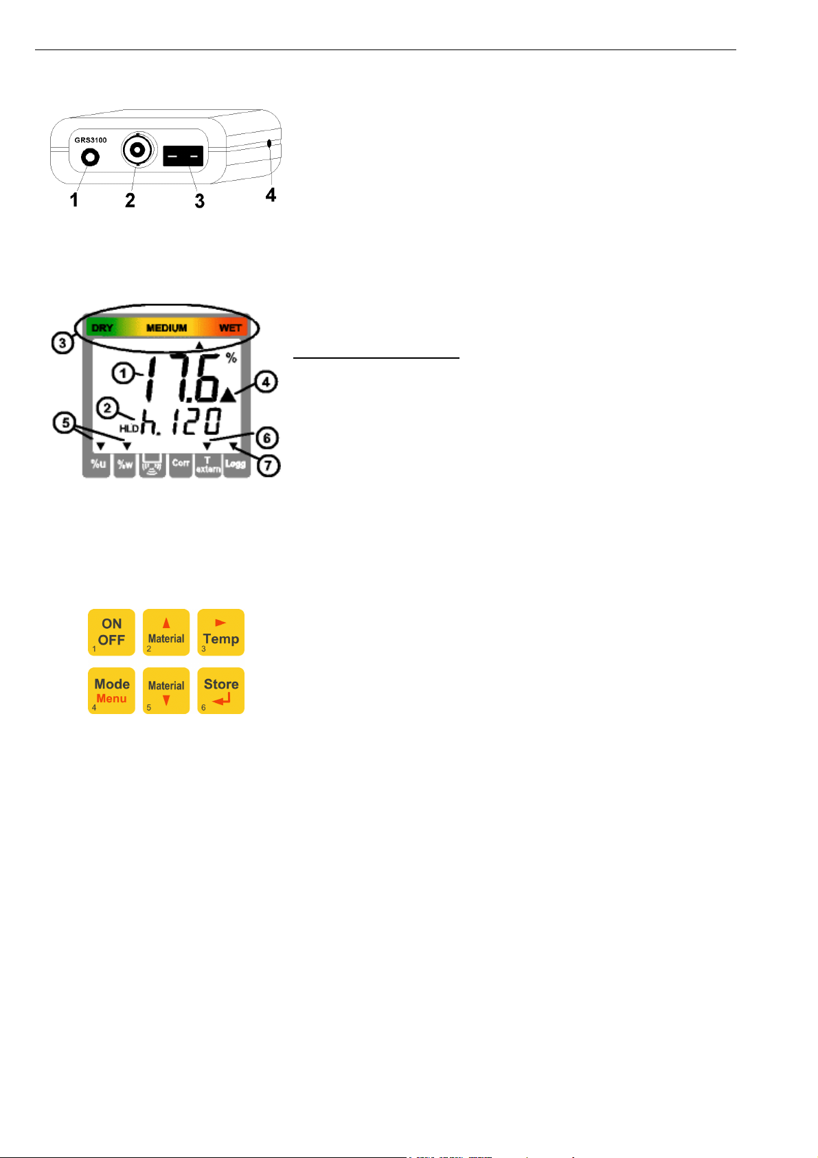
1.4 Connections
1. Output: Operation as interface: Connect to optically isolated
interface adapter (accessory: GRS 3100, GRS3105 or USB3100)
Operation as analogue output: Connection via suitable cable.
Attention: The output mode has to be configured (p.r.t 2.7) and
influences battery life!
2. Sensor-connection: BNC
3. Temperature-probe-connection: Thermocouple type K (NiCr-Ni)
for temperature-compensation with an external temperature-probe
4. The mains socket is located at the left side of the instrument.
1.5 Display Elements
1 = Main Display:
2 = Auxiliary Display:
Special display elements:
3 = Moisture estimation:
4 = Warning triangle:
5 = “%u” or “%w”
6 = T external-arrow
7 = Logg-arrow
All remaining arrows have no function in this version.
Currently measured material moisture
[percent moisture content]
HLD: Measure value is ‘frozen‘ (Button 6)
Currently selected material
(or temperature when pressing Button 3)
Estimation of the material condition: via top
arrows: DRY - MEDIUM - WET
Indicates low battery
Displays unit: moisture content u or wet basis
moisture content w
Appears if an external temperature-probe is
connected and automatic temperature
compensation is activated.
Shown if logger function is selected,
flashes if cyclic logger is running
1.6 Pushbuttons
key 1: On/Off key
key 4: Set/Menu
press (Menu) for 2 sec.: configuration will activated
key 2, 5: During measure: select a material
p.r.t.: 4.2 Pre-selection of favourite materials ('Sort')
List of selectable materials:
Appendix A; Appendix B
With manual temperature compensation:
When displaying temperature (call via button 3 ‚Temp‘):
Input of temperature
up/down for configuration:
to enter values or change settings
Key 6:
Key 3: During the measure: shortly displaying temperature or changing to temperature input.
Store/↵↵↵↵:
- Measurement:
with Auto-Hold off: Hold current measuring value ('HLD' in display)
with Auto-Hold on: Start a new measure, which is ready when 'HLD' appears in the display
refer to chapter 3.4 Auto-Hold Function
or calling of the logger functions (refer to chapter 5)
- Set/Menu or temperature input:
confirming of selected input, return to measure
Page 5
H60.0.12.6C-09 Operating Manual GMH3850 page 5 of 20
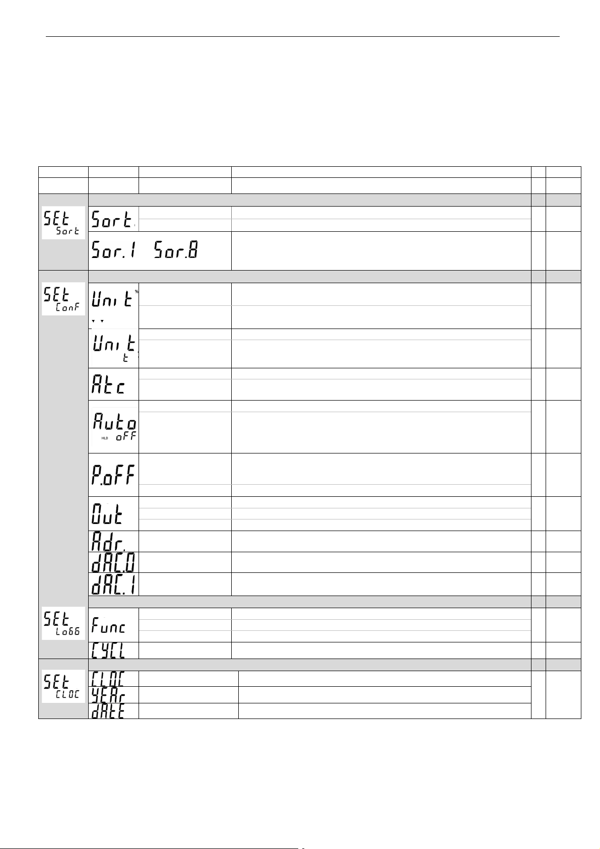
2 Device Configuration
Note: Some menu items will be shown depending on the actual device configuration (e.g. there are some
items disabled when the logger contains data). Please note the hints by the menu items.
For configuration of the device press "Menu"-key (key 4) for 2 seconds, the main menu will be shown (main display:
“SEt”). Choose the desired menu branch by pressing the "Menu"-key (key 4). By pressing “4” (key 3) the referring
parameters can be chosen. The referring values are changed by pressing the keys "5" (key 2) or "6" (key 5) (Choice
of parameter: “4”). Pressing “Menu” (key 4) again will jump back to the main menu selection and stores the settings.
Use key " Store/↵↵↵↵" (key 6) to leave configuration.
Menu Parameter Values Meaning
key Menu
Set Sort
Set Conf
key
4
key5 or
6
Set Sort: limitation of the material selection
off:
1...8:
Unrestricted material selection via key 2 and 5
Material selection in-between 1 up to 8 selectable materials
selectable materials (not available if Sort = off)
....
Select the desired material that should be available during the
measure via key 2 and 5.
Set Configuration: Generic Settings
Arrow bottom left
points to “%u”
Arrow bottom left
points to
°C
°F
“%w”
Moisture display = moisture content [%u]
Moisture display = wet-basis moisture content [%u]
All temperature values are in degrees Celsius
All temperature values are in degrees Fahrenheit
p.r.t.
4.2
*
4.2
*
*
Set Logg
Set CLOC
oFF
on
oFF
on
1...120
oFF
oFF
SEr
dAC
01, 11 .. 91
0.0 ... 100.0%
0.0 ... 100.0%
Atc off: temperature input for compensation via keys
Atc on: temperature compensation via internally measured temperature
or external probe
Auto HLD off: continuous measuring.
Auto-HLD on: when reaching a stable measuring result, this will be
frozen with-HLD. When pressing the store-key a new measure will be
initiated. If logger is switched on (‚Func CYCL‘, ‚Func Stor‘): device
works like setting would be “auto-HLD off”
Power-off delay in minutes.
Device will be automatically switched off as soon as this time has
elapsed if no key is pressed/no interface communication takes place
Power-off function inactive (continuous operation, e.g. mains operation)
Function of the output: No output function, lowest power consumption
Output is serial interface
Output is analogue output 0...1V
Base Address when Output = Serial Interface :
Base address of device for interface communication.
Enter desired moisture value at which the analogue output potential
should be 0V
Enter desired moisture value at which the analogue output potential
should be 1V
Set Logger: Configuration Of Logger Function
CYCL Cyclic: logger function ‚cyclic logger‘
Stor Store: logger function ‚individual value logger‘
oFF
0:30 ... 60:00
no logger function
Cycle time of cyclic logger [minutes:seconds]
Set Clock: Setting Of Real Time Clock
HH:MM Clock: Setting of time hours:minutes
YYYY Year
TT.MM Date: day.month
**3.3
*
3.4
6
6.1
6.2
6.2
*5
*5.2
Hint: The settings will be set to the settings ex works, if keys ‘Set‘ and ‘Store‘ are pressed simultaneously
for more than 2 seconds.
(*) If the logger memory contains data already, the menus/parameters marked with (*) can not be invoked!
If these should be altered the logger memory has to be cleared before!
If the manual logger contains data (Logger: ‘Func Stor’), the first menu displayed will be: ‘rEAd Logg’
please refer to chapter 5.1
Page 6

H60.0.12.6C-09 Operating Manual GMH3850 page 6 of 20
3 Some Basics Of Precision Material Moisture Measuring
3.1 Moisture Content u and Wet-Basis Moisture content w
Depending on the Application one of the two units is necessary.
Carpenters, joiners and the like commonly use the moisture content u (sometimes referred to as MC).
When evaluating firewood, wood chips etc., the wet basis moisture content w is needed.
The instrument can be configured to both of the values. Please refer to chapter “configuration“.
Moisture content u or MC (relative to dry weight) = dry basis moisture content (mind the arrow at left bottom!)
The unit is %, sometimes used: % MC.
The unit expresses the moisture content like calculated below:
Or:
Moisture content u [%] = (weight
- weight
wet
) / weight
dry
dry
*100
weight
weight
weight
Moisture content u [%] = (weight
: weight of the wet material
wet
: weight of water in the wet material
water
: oven-dry weight of material
dry
water
) / (weight
) *100
dry
Example: 1kg of wet wood, which contains 500g of water has a moisture content u of 100%
Wet-Basis Moisture Content w (relative to total weight, mind the arrow at left bottom!)
The wet-basis moisture content expresses the ratio of the mass of water to the total mass of the substance. The ratio
is represented by the following equation (the unit is % as well):
wet-basis moisture w[%] = (weight
Or: wet-basis moisture w[%] = (weight
- weight
wet
) / weight
water
) / weight
dry
*100
wet
wet
*100
Example: 1kg of wet wood, which contains 500g of water has a moisture content u of 50%
3.2 Special features of the device
466 wood specimens and 28 building materials are stored directly in the memory of the device:
Thus more exact measurements could be reached than with common devices with group selections would ever reach.
Even the usage of complex conversion tables for building materials won’t be necessary any more!
Example: Common wood-moisture-measuring-devices use one single group for spruce and oak, in reality the deviation
of these characteristic curves is more than 3%! (Base for this statement are complex statistical surveys, considered
measuring range 7-25%). This random error will not occur for the whole GMH38xx series, with the help of individual
characteristic curves highest resolution is achieved.
Extreme wide measuring range: 0-100% (depending on characteristic curve) percent moisture content in wood.
Moisture estimation: Additionally to the measuring value, an individual moisture estimation will be displayed
simultaneously.
3.3 Automatic temperature-compensation ('Atc')
An exact temperature compensation is important for a reliable wood-moisture-measuring. These devices feature a high
quality thermocouple-input for type k thermocouples. Thus you could connect common surface-temperature-probes –
The needed measuring-time ‘afield’ will be drastically lowered compared to common (non-surface-)temperature-probes
The used temperature-value therefor is:
Menu Used temperature-value Aux. Display
Atc on
Atc off Independent from
Attention: When connecting a probe that is non insulated you must have to observe not touching the wood or
Temperature-probe connected Temperature-measuring through connected probe Display-arrow
‘T extern‘
No temperature-probe connected Device-internal temperature-measuring
Manual input of temperature: shortly press Temp-Button
temperature-probe
then use 5 (button 2) or 6 (button 5) to input the
temperature confirm selection with ‘Store‘(button 6)
Table 4.2: Using of the temperature-compensation
the electrodes nearby the unshielded electrode. We suggest using our insulated probe GTF38
(already included in standard case sets SET38HF and SET38BF).
Page 7

H60.0.12.6C-09 Operating Manual GMH3850 page 7 of 20
3.4 Auto-Hold Function
Particularly when measuring dry wood, electrostatic charges and other similar noise could dither the measuring value.
With activated auto-hold function the device will acquire an exact measuring value automatically. During that, the
device could be put down to avoid noise through discharge of the clothing etc. After having acquired the measuring
value, the display will change to ‘HLD’: The value will be frozen as long as a new measuring is initiated by pressing
button 6 (store).
Attention: If the logger is switched on (‘Func CYCL’ or ‘Func Stor’), the auto-hold function can not be used.
The device works like it is set to Auto-HLD = off.
3.5 Measuring In Wood: Measuring With Two Measuring-Pikes
Normally wood is measured with measuring-pikes. Used electrodes: impact-electrode GSE91 or GSG91, reciprocating
piston electrode GHE91. For measuring wood, punch in the measuring-pikes across to the wood-grain, having a good
contact between the pikes and the wood (measuring along wood-grain deviates minimal)
Select correct wood-sort (refer to Appendix A).
Ensure measuring the correct temperature (see chapter 3.3).
Hint: The special GTF38 temperature-probe can be stuck into a hole punched in with the
electrode before (see picture on left).Now read the measuring-value or when having
activated the auto-hold-function initiate a new measuring by pressing Store/↵↵↵↵ (button 6) .
The measured resistance will be extremely high when measuring dry wood (<15%) thus
the measuring will need more time to achieve its final value. Among other things static
discharge could momentarily falsify the measuring. Therefore beware of static discharge
and wait long enough until a stable measuring value is displayed (unstable: „%“ blinking)
or use the auto-hold-function (see chapter 3.4 Auto-Hold Function).
Reciprocating piston
electrode GHE91 with
temperature-probe GTF38
It is measured between the measuring-pikes insulated among each other. Requirements for an exact measurement:
- choose right correct place to measure: place should be free of irregularities like resin–clusters, knurls, rifts, etc.
- choose correct depth: Recommendation for trimmed timber: punch in the pikes up to 1/3 of the material thickness.
- Perform multiple measurements: the more measurements will be averaged, the more exact the result will be.
- Pay attention to temperature-compensation: the temperature-probe should be measuring the temperature of the
moisture-measuring-place when measuring with external temperature-probe (Atc on).
Without temperature-probe: let the device adapt to the temperature of the wood (Act on) or enter the exact
temperature manually (Act off).
Frequent sources of errors:
- Attention with oven-dried wood: the moisture dispersion may be irregular, often in the core is more moisture than
on the edge.
- Surface-moisture: The wood-edge could be more humid than the core if the wood had been stored outside and
e.g. was in rain.
- Wood preservative and other treatment could falsify the measuring.
- Fouling at the connections and round the pikes could result in erroneous measurement, especially with dry wood.
Most accurate measurements can be carried out within the range of 6 to 30%.
Beyond this range the acquirable accuracy will lessen, but the device will deliver reference
values still sufficient for the practitioner.
3.6 Measuring Other Materials
3.6.1 ‘Hard‘ Materials (concrete or similar): Measuring with brush-type probes (GBSL91 or GBSK91)
Drill two holes with Ø6mm (GBSK91) or Ø 8mm (GBSL91) at intervals
of 8 to 10cm into the material to be measured. Do not use edgeless
drills: the resulting heat will evaporate the moisture which will result in
faulty measures. Wait for at least 10min, blow out the holes to clean
them from dust. Apply conductivity compound on the brush-type probes
and stick them into the holes. Choose correct material (see Appendix
B: Additional materials), read the measuring value. Observe that the
holes dry out by-and-by, and the device will measure a value too low, if
you want to use them several times.
This effect can be compensated by using conductivity compound: insert
profuse conductivity compound between the holes and the brush-type
probe, and let the electrode stick in the hole for about 30min before
measuring (with the device switched off ). Temperature-compensation
Measuring with brush probe GBSL91
3.6.2 ‘Soft‘ Materials (polystyrene or similar): Measuring with Measuring-pikes or -pins (GMS 300/91)
Useable electrodes: impact electrode GSE91 or GSG91, reciprocating piston electrode GHE91.
Procedure as described in chapter measuring in wood.
plays no role when using the building material measuring.
Page 8

H60.0.12.6C-09 Operating Manual GMH3850 page 8 of 20
3.6.3 Measuring bulk cargo, bales and other special measures
Usable probes e.g. injection probe GSF38 or measuring pins GMS 300/91 mounted on GSE91 or GSG91.
Measuring of splints, wood chips, insulating material and similar:
When using injection probes or measuring pins oscillating movements have to be avoided when pushing in the probes.
Otherwise hollows between the probes and the material may falsify the measuring. The material should be sufficiently
compressed. When in doubt repeat the measuring a few times: the highest measuring value is the most exact one.
Especially when using the injection probe pay attention having a foulness-free plastic insulator (situated immediately
underneath the measuring-pike).
Measuring bale of straw and hay bale: Always inject the electrodes form the plain side of the bale, never from the
round side, the probe can be inserted much more slightly.
3.7 Measuring of materials, having no characteristic curves stored
Choose the representative universal material group „h.A“, „h.b“, „h.c“ and „h.d“(for example corresponding to A,B,C
and D of the GHH91) if a conversion table exists.
Attention: The moisture evaluation wet/dry of these material groups is only valid for wood!
Please keep in mind the following when using the temperature-compensation:
Automatic temperature-compensation should always be activated when measuring wood (Act on), with all other
materials the automatic temperature-compensation should be switched off (Act off) and a manual temperature of 20°C
should be entered.
Additionally at GMH3850: The GMH3850 can store up to 4 additional user characteristic curves. For this the
corresponding reference point measurements for the respective material has to be carried out, from which the exact
moisture content has to be dedicated with the Darr-Probe or the CM-Method. The Results can be stored in the device
with the help of the GMHKonfig-Software, and can be accessed by the device directly .
4 Hints For The Special Functions
4.1 Moisture estimation ('WET' - 'MEDIUM' - 'DRY')
Additionally to the measuring value, an individual moisture estimation will be displayed simultaneously. This moisture
estimation is only a guidance value, the final evaluation is depending on the application of the material e.g:
Cement floor pavement ZE, ZFE without additives: Readiness without floor heating at 2,3% with floor heating 1,5%
Anhydrit floor pavement AE, AFE: Readiness without floor heating at 0,5% with floor heating 0,3%
Also firewood may be already usable while instrument still displays ‘wet’!
Corresponding Standards and Instructions must be observed!
The Device can only complement the skill of a tradesman or investigator but cannot replace it!
4.2 Pre-selection of favourite materials ('Sort')
A pre-selection of different materials (up to 8) can be selected from the menu for an effective working with the device.
For example you can set the Menu Sort to 4 and save the desired materials in Sor.1, Sor.2, Sor.3 and Sor.4 if you only
measure 4 different materials. Please refer to chapter 2 Device Configuration.
Only the 4 desired materials can be selected via the buttons up and down, when exiting the menu, a changing during
the measurement can be done comfortably. All materials will be available when setting Sort to off. Sor.1 to Sor.4 will
still be available in the ‘background’, when setting the menu Sort to 4 the limited selection of the 4 entered materials will
be active again. You only want to measure one material: set the menu Sort to 1 you cannot change to another material,
thus a faulty operation is impossible.
4.3 Individually Programmable Characteristic Curves
There are 4 individually programmable characteristic curves integrated.
By using them there can be used other material curves than the already integrated ones.
The programmable curves can be read and programmed by the software GMHKonfig.
As standard they are pre set with the REF-curve. This curve is the base of the determination of user specific curves.
Each curve is defined by a table with two columns (measuring value REF [%] / display value [%]) with 20 rows.
The name of the curve , which is displayed in lower display, can be set individually. Characters which cannot be
displayed are displayed as a space character.
Each curve contains also limit values for wet and dry estimation.
As temperature compensation there is a choice between the standard compensation for wood or linear compensation.
If there should be used no temperature compensation should be used: Choose linear compensation and enter 0 as
compensation factor.
Linear temperature compensation:
MC compensated(T) = MC uncompensated * (1+ compensation factor/10000 * (T-20°C)
MC = moisture content
Page 9
H60.0.12.6C-09 Operating Manual GMH3850 page 9 of 20
5 Operation Of Logger
The device supports two different logger functions:
„Func-Stor“: each time when „store“ (key 6) is pressed a measurement will be recorded.
„Func-CYCL“: measurements will automatically be recorded at each interval, which was set in the logger menu
‚CYCL‘ until the logger will be stopped or the logger memory is full.
The recording is started by pressing „Store“ 2 seconds.
The logger records 1 measurement result each time
For the evaluation of the data the software GSOFT3050 (V1.7 or higher) has to be used. The software also allows easy
configuration and starting of the logger.
When the logger is activated (Func Stor or Func CYCL) the hold and auto hold functions are no longer available, key 6
is solely used for the operation of the logger functions.
5.1 „Func-Stor“: Storing Single Measurements
Each time when „store“ (key 6) is pressed a measurement and its time stamp will be recorded.
The recorded data can be viewed either in the display (when calling the configuration an additional menu „REAd LoGG“
is displayed, see below) or by means of the interface and a PC with GSOFT3050-software.
The logger stores the current measuring, independent from the stability of the value.
The material curve can be altered like during a normal measuring.
Max. number of measurings: 99
A measuring contains: - current measuring value at the time of recording
- temperature value at the time of recording
- material curve at the time of recording
- time and date of the recording
After each recording „St. XX“ will be displayed for a short time. XX represents the number of the recording.
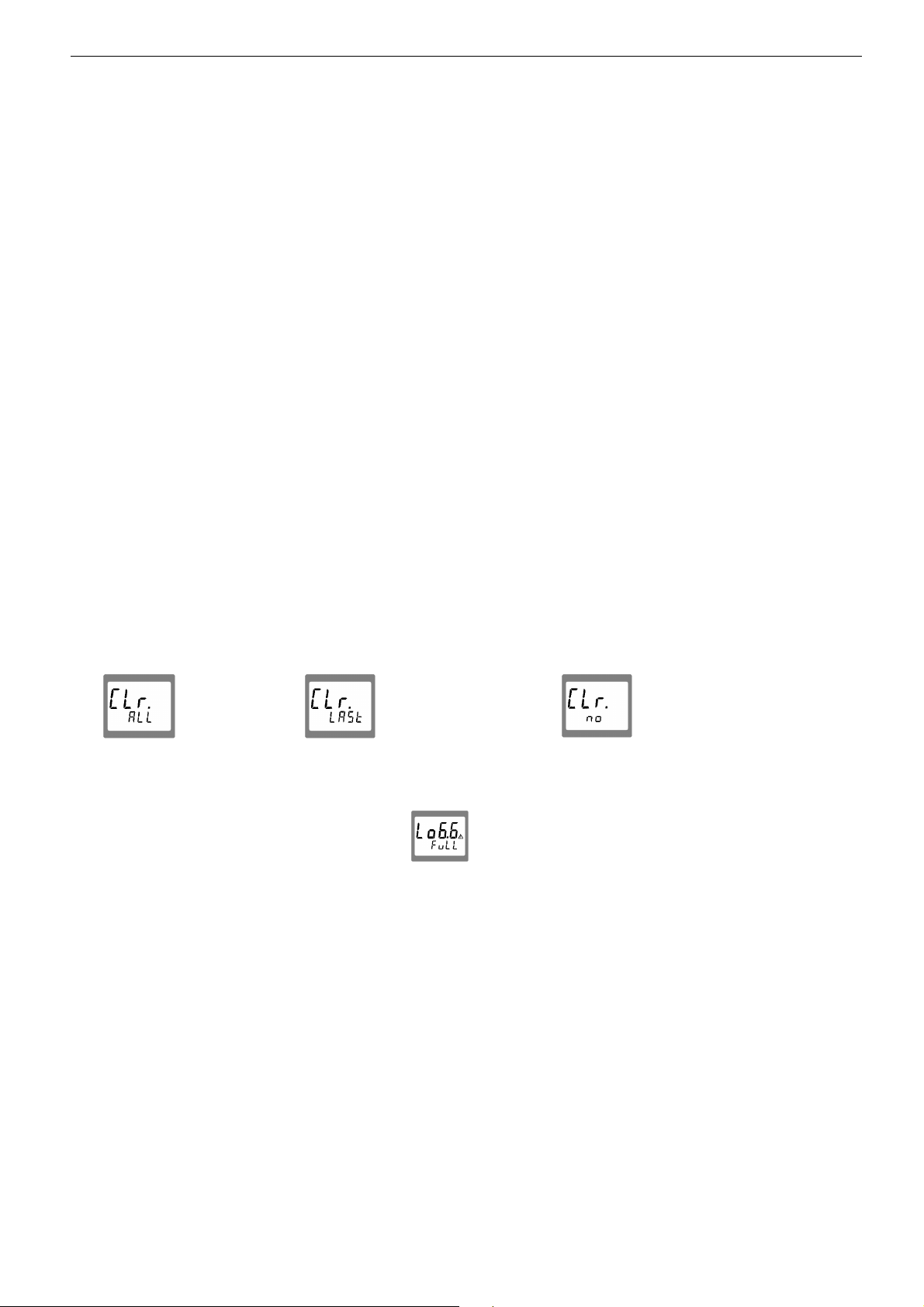
When logger memory contains recordings already:
When „Store“ is pressed for 2 seconds, the choice for clearing the logger memory will be displayed:
Clear all
recordings
The selection can be made by 5 (key 2) and 6 (key 5). "Quit" (key 6) enters the choice.
If the logger memory is full, the display will show:
Viewing Recorded Measurings
Within the „LoGG Stor“ function the measurings can be viewed directly in the display not only by means of a computer
(like at „Func CYCL“): press 2 seconds „Set“ (key 4): The first menu displayed now is „rEAd LoGG“ (read logger data).
After pressing 4 (key 3) the measurement recorded last will be displayed, changing between the different data
referring to the measurement also is done by pressing 4.
Changing the measurement is done by pressing the keys 5 or 6.
Clear the last
recording
Clear nothing
(cancel menu)
Page 10

H60.0.12.6C-09 Operating Manual GMH3850 page 10 of 20
5.2 „Func-CYCL“: Automatic Recording With Selectable Logger-Cycle-Time
The Logger-Cycle-Time is selectable (p.r.t. Configuration). For example „CYCL“ = 1:00: A measuring is recorded after
each 60 seconds.
Special feature of this logger function: The device will change to a ‘sleeping state’ during the measurings (lower
display shows a count-down to the next measuring). Just before a new measuring should be recorded, the devices
wakes up and measures until a stable measuring value is evaluated. This value will be stored, the device enters the
sleeping state again. This procedure reduces the battery consumption dramatically, with a fresh zinc carbon battery the
device is capable of recording more than a month without an additional mains adapter.
When the cyclic logger contains data (independent if running or stopped), the material cannot be changed.
The value measured during the last recording is shown in the upper display. During the pauses no measuring is done!
An adequate message is stored, if no stable value could been measured during the interval.
Max. number of measurings: 10000
Cycle time: 0:01...60:00 (minutes:seconds, min 1s, max 1h), selectable in the configuration
A measuring contains: - current measuring value at the time of recording
- temperature at the time of recording
Recording time: > 1 month (with output activated: OUT = SEr)
> 3 months (with output deactivated: OUT = off)
With mains adapter: limited just by memory and cycle time, up to 416 days
Starting a recording:
By pressing "Store" (key 6) for 2 seconds the recording will be initiated. After that the display shows ‘St.XXXX‘ for a
short time whenever a measuring is recorded. XXXXX is the number of the measuring 1..9999.
If the logger memory is full, the display will show:
The recording automatically will be stopped.
Stopping the recording manually:
By pressing "Store" (key 6) the recording can be stopped manually. Then the following choice appears:
Stop the
recording
Do not stop the
recording
The selection can be made by 5 (key 2) and 6 (key 5). "Quit" (key 6) enters the choice.
Note: If you try to switch off the instrument in the cyclic recording operation You will be asked once again if the
recording should be stopped.
The device can only be switched off after the recording has been stopped!
The Auto-Power-Off-function is deactivated during recording!
Clear Recordings:
When „Store“ is pressed for 2 seconds, the choice for clearing the logger memory will be displayed:
Clear all
recordings
Clear nothing
(cancel menu)
The selection can be made by 5 (key 2) and 6 (key 5). "Quit" (key 6) enters the choice.
Page 11

H60.0.12.6C-09 Operating Manual GMH3850 page 11 of 20
6 Output
The output can be used as serial interface (for GRS3100 or GRS3105 interface adapters) or as analogue output (01V). If none of both is needed, we suggest to switch the output off, because battery life then is extended.
6.1 Interface - Base Address ('Adr.')
By using an electrically isolated interface converter GRS3100, GRS3105 or USB3100 (accessory) the device can be
connected to a PC.
With the GRS3105 it is possible to connect up to 5 instruments of the GMH3000 family to a single interface (please
also refer to GRS3105-manual). As a precondition the base addresses of all devices must not be identical. In case
several devices will be connected via one interface make sure to configure the base addresses accordingly. In order to
avoid transmission errors, there are several security checks implemented (e.g. CRC).
The following standard software packages are available for data transfer:
! EBS9M: 9-channel software to record and display the measuring values
! EASYControl: Universal multi-channel software (EASYBUS-, RS485-, and/or GMH3000- operation possible)
for real-time recording and presentation of measuring data in the ACCESS®-data base format.
In case you want to develop your own software we offer a GMH3000-development package including
- an universally applicable 32bit Windows functions library ('GMH3000.DLL') with documentation that can be used by
all 'serious' programming languages.
- Programming examples for Visual Basic 6.0™, Delphi 1.0™, Testpoint™, Labview™
The Device has 2 Channels:
- Channel 1: Material-moisture in % and base-address
- Channel 2: Temperature
Note: The measuring and range values read via interface are always in the selected display unit (°C/°F)!
Supported Interface-functions:
1 2 Code Name/Function 1 2 Code Name/Function
xX0
xX3
x 12 read ID-no. x 205
x X 176
x X 177
x X 178 read measuring range unit x x 215
x X 179
x X 180
X 194 set display unit x 222 read turn-off-delay
x X 199
x X 200
x X 201
read nominal value
read system status
read min measuring range
read max measuring range
read measuring range decimal point
read measuring type
read measuring type in display
read min. display range
read max. display range
x x 202
x x 204
x 208
x x 214
x x 216 read zero displacement
x x 217 set zero displacement
x 223 Set turn-off-delay
x 240
x 254
read unit of display
read decimal point of display
read extended measuring type in display
read channel count
read scale correction
set scale correction
Reset
read program identification
6.2 Analogue Output – Scaling with DAC.0 and DAC.1
With the DAC.0 and DAC.1 values the output can be rapidly scaled to Your efforts.
Keep in mind not to connect low-resistive loads to the output, otherwise the output value will be wrong and battery life is
decreased. Loads above ca 10kOhm are uncritical.
If the display exceeds the value set by DAC.1, then the device will apply 1V to the output
If the display falls below the value set by DAC.0, then the device will apply 0V to the output
In case of an error (Err.1, Err.2, no sensor, etc.) the device will apply slightly above 1V to the output.
Plug wiring:
GND
+Uout
Attention!
The 3
rd
contact has to be left floating!
Only stereo plugs are allowed!
Page 12

H60.0.12.6C-09 Operating Manual GMH3850 page 12 of 20
7 Fault and System Messages
Display Meaning Remedy
low battery voltage, device will continue to work for a short
time
If mains operation: wrong voltage replace power supply, if fault continues to
low battery voltage replace battery
If mains operation: wrong voltage Check/replace power supply, if fault continues
replace battery
exist: device damaged
to exist: device damaged
No display
or
weird display
Device does not
react on keypress
----
Err.1
Err.2
Err.7 system error return to manufacturer for repair
low battery voltage replace battery
If mains operation: wrong voltage Check/replace power supply, if fault continues
to exist: device damaged
system error Disconnect battery or power supply, wait
some time, re-connect
device defective return to manufacturer for repair
Sensor error: no material connected (meas. Value below
permissible range), no valid signal
charge at the probe, device will discharge (resp. at dry wood) Wait until probe has discharged
Sensor broken or device defective return to manufacturer for repair
Value exceeding measuring range Check: Is the value exceeding the measuring
Wrong probe connected Check probe
Probe or device defective return to manufacturer for repair
Non-floating probe near the unshielded electrode Insulate probe or measure at shielded
Value below display range
Wrong probe connected Check probe
Probe, cable or device defective return to manufacturer for repair
Connect meas. material
range specified? ->temperature too high!
electrode
Check: Is the
range specified? -> temperature too low
value below the measuring
8 Application in the glued timber construction acc. to
DIN 1052-1 (MPA certified)
The instrument with its curve h.460 (Fir) was certified by the MPA Stuttgart (Otto Graf institute) for applications in the
glued timber construction according to DIN 1052-1 with the following equipment:
- measuring cable GMK38
- reciprocating piston electrode GHE91 (recommended) or impact electrode GSE91
!
9 Inspection of the accuracy / Adjustment Services
Accuracy can be inspected with the testing adapter GPAD 38 (extra equipment).
To check precision select material characteristic curve “.rEF”, choose as moisture display „%u“ and connect the testing
adapter to the needles. The device must display the printed value for the GMH38xx
If the precision is no more corresponding to the imprint of the GPAD 38, we suggest to send the device to the
manufacturer for a new adjustment.
Page 13

H60.0.12.6C-09 Operating Manual GMH3850 page 13 of 20
10 Specification
Measuring Channel1 Channel2
Principle Resistive material-moisture-measuring Temperature-measuring thermocouple type K
matching DIN EN 13183-2: 2002 or internal temperature-measuring
Char. curve 466 different kinds of wood matching DIN EN 60584-1: 1996, ITS90
28 different building materials
4 individually programmable material curves
Probe connection BNC Plug floating connector for mini-blade-terminal
Meas. range 0.0...100.0 % moisture content thermocouple: -40.0... +200.0°C / -40.0... + 392.0°F
(depending on characteristic curve) int. temp.-Meas.: -30.0...75.0°C / -22.0...167.0°F
equal to ca. 3kOhm ... 2TerraOhm
Resolution 0,1%
Estimation Estimation of the material condition in 9 steps from DRY to WET
Accuracy Device without probe ±1Digit (at nominal-temperature)
Temperature drift < 0.005 %
Nominal temperature 25°C
Ambient Temperature -25 ... +50°C (-13 .. 122°F)
Storage temperature -25 ... +70°C (-13 ... 158°F)
Housing Dimension: 142 x 71 x 26 mm (L x B x D)
Weight approx. 155 g
Output: 3.5mm audio plug, stereo
Selectable as serial interface: via optically isolated interface adapter GRS3100, GRS3105 or USB3100 (p.r.t. accessories)
or analogue output: 0..1V, freely scaleable (resolution 13bit, accuracy 0.05% at nominal temperature, cap. load <1nF)
Real time clock: Integrated clock with date and year
Logger: 2 Functions: individual value logger („Func–Stor“) and cyclic logger („Func–CYCL“)
Memory: Stor: 99 data sets; CYCL: 10000 data sets
Cycle time CYCL:
Power Supply 9V-Battery, type IEC 6F22 (included) as well as additional d.c. connector (diameter of internal pin 1.9 mm)
Power Consumption output off approx. 2.5mA
Display Two 4 digits LCD’s (12.4mm high and 7 mm high) for material moisture temperature or characteristic curve,
Pushbuttons 6 membrane keys for on/off switch, menu operation, characteristic curve, hold-function etc.
Hold Function Press button to store current value.
Automatic-Off-Function Device will be automatically switched off if no key is pressed/no interface communication takes place for
moisture content 0.1°C / 0,1°F
Wood: ±0.2% moisture content (deviation from Type K: ± 0.5% m.v. ± 0.3°C
characteristic curve, range 6..30%) int. t.-measuring: ± 0.3°C (is type K reference junction)
building mat.: : ±0.2% moisture content (dev. from
char. curve, range depending on char. curve)
moisture content per 1K 0.01% per 1K
Relative humidity 0 ... 95 %RH (non condensing)
impact resistant ABS, membrane keyboard, transparent panel.
Front side IP65, integrated pop-up-clip for table top or suspended use
directly connectable to RS232- or USB-interfaces.
0:30...60:00 (minutes:seconds, min 1s, max 1h)
for external 10.5-12V direct voltage supply. (suitable power supply: GNG10/3000)
output serial interface: approx. 2.7mA
analogue output: approx. 3.0mA
cyclic logger sleeping state with output deactivated: < 0.1mA
cyclic logger sleeping state with activated serial interface: < 0.3mA
hold function, etc. as well as additional pointing arrows.
the time of the power-off delay. The power-off delay can be set to values between 1 and 120 min.; it can be
completely deactivated.
EMC: The device corresponds to the essential protection ratings established in the Directives of the European
Parliament and of the council on the approximation of the laws of the memberstates relating to the
electromagnetic compatibility (2004/108/EC).
EN61326 +A1 +A2 (Appendix B, class B), additional error: < 1% FS
Page 14

H60.0.12.6C-09 Operating Manual GMH3850 page 14 of 20
Appendix A: Sorts of wood
Select kind of wood you want to measure, enter number on the device, e.g. birch = h. 60
Identification Number Comment Range
Group A h. A Wood-group A (equal to GHH91 selector “A”) 0..82%
Group B h. B Wood-group B (equal to GHH91 selector “B”) 1..95%
Group C h. C Wood-group C (equal to GHH91 selector “C”) 2..107%
Group D h. D Wood-group D (equal to GHH91 selector “D”) 3..121%
AS/NZS 1080.1 h. AS Australian reference characteristic curve 4..91%
Group Spruce-Pine-Fir h.402 Softwood-Group 6..99%
Fir, Picea abies Karst. h.460 applications in the glued timber construction, MPA certified 6..101%
Wood chips GSF38 h.461 Softwood chips with probe GSF38 or GSF38TF 5..145%
GMH38 reference .rEF Internal reference for determining additional characteristic curves /
calculation tables (without temperature-compensation)
Abura
Afrormosia
Afzelia
Agba
Albizia / Iatandza, New
Guinea
Albizia / Iatandza,
Solomon Island
Alder, Blush
Alder, Brown
Alder, Common
Alder, Rose
Alerce
Amberoi
Amoora, New Guinea
Andiroba
Antiaris, New Guinea
Apple, Black
Ash Silvertop
Ash, American
Ash, Bennet's
Ash, Crow's
Ash, European
Ash, Hickory
Ash, Japanese
Ash, Red
Ash, Scaly
Ash, Silver (Northern)
Ash, Silver (Queensland)
Ash, Silver (Southern)
Ash, Silver, New Guinea
Aspen, Hard
Ayan
Balau
Balau, red
Balsa
Basralocus / Angelique
Basswood
Basswood, Fijian
Basswood, Malaysian
Basswood, New Guinea
Hallea ciliata
Pericopsis elata
Afzelia spp.
Gossweilerodendron
balsamiferum
Albizia falcatara
Albizia falcatara
Solanea australis
Caldcluvia paniculosa
Alnus glutinosa
Caldcluvia
australiensis
Fitzroya cupressoides
Pterocymbium beccarii
Amoora cucullata
Carapa guianensis
Antiaris toxicaria
Planachonella australis
Eucalyptus sieberi
Fraxinus americana
Flindersia bennettiana
Flindersia australis
Fraxinus excelsior
Flindersia ifflaiana
Fraxinus mandshurica
Flindersia excelsa
Ganophyllum falcatum
Flindersia schottina
Flindersia bourjotiana
Flindersia schottina
Flindersia amboinensis
Acronychia laevis
Distemonanthus
benthamianus
Shorea laevis
Shorea guiso
Ochroma pyramidale
Dicorynia guianensis
Tilia americana
Endospermum
macrophyllum
Endospermum
malacense
Endospermum
medullosum
h.2
h.3
h.4
h.426
h.8
h.9
h.10
h.11
h.131
h.12
h.13
h.14
h.15
h.16
h.7
h.17
h.27
h.132
h.18
h.19
h.133
h.20
h.134
h.21
h.22
h.23
h.24
h.25
h.26
h.28
h.285
h.31
h.32
h.33
h.34
h.228
h.35
h.36
h.37
7..50%
6..47%
8..42%
6..64%
5..88%
4..72%
5..65%
7..69%
2..107%
6..71%
7..61%
5..67%
3..94%
5..59%
6..83%
7..62%
2..90%
5..79%
6..76%
7..69%
7..56%
6..71%
4..79%
5..67%
5..90%
7..70%
6..88%
7..82%
5..82%
5..66%
7..54%
4..54%
4..68%
4..91%
6..55%
4..85%
4..63%
5..116%
5..76%
Basswood, Silver
Basswood, Solomon
Island
Bean, Black
beech, damped
beech, european -
Beech, Myrtle
Beech, New Zeeland Red
(hearted untreated)
Beech, New Zeeland Red
(sapwood boron)
Beech, New Zeeland Red
(sapwood untreated)
Beech, Silky
Beech, Silver
Beech, Silver (sapwood
tanalith)
Beech, Silver (sapwood
untreated)
Beech, Wau
Beech, White (Fiji)
Beech, White
(Queensland)
Bintangor / Calophyllum,
Fijian
Bintangor / Calophyllum,
Malaysian
Bintangor / Calophyllum,
New Guinea
Bintangor / Calophyllum,
Phillipines
Bintangor / Calophyllum,
Solomon Islands
Binuang
Birch, American
Birch, European
Birch, White
Bishop Wood (Fiji)
Blackbutt
Blackbutt, Western
Australia
Blackwood
Bloodwood, Red
Bollywood
Bossime
Polyscias elegans
Polyscias elegans
Castanosperum
australe
Fagus sylvatica
Fagus sylvatica
Nothofagus
cunninghamii
Nothofagus fusca
Nothofagus fusca
Nothofagus fusca
Citronella moorei
Nothofagus menziesii
Nothofagus menziesii
Nothofagus menziesii
Elmerrilla papuana
Gmelina vitiensis
Gmelina leichardtii
Calophyllum
leucocarpum
Calophyllum curtisii
Calophyllum
papuanum
Calophyllum
inophyllum
Calophyllum kajewskii
Octomeles sumatrana
Betula lutea
Betula pubescens
Schizomeria ovata
Bischofia javanica
Eucalyptus pilularis
Eucalyptus patens
Acacia melanoxylon
Corymbia gunmifera
Litsea reticulata
Drypetes spp,
h.38
h.39
h.40
h.87
h.86
h.41
h.42
h.43
h.44
h.45
h.46
h.47
h.48
h.49
h.50
h.51
h.53
h.54
h.55
h.56
h.57
h.130
h.59
h.60
h.58
h.61
h.62
h.63
h.64
h.66
h.67
h.70
7..72%
4..65%
6..87%
6..55%
5..85%
6..76%
7..87%
2..97%
5..84%
8..66%
8..58%
6..76%
4..92%
7..96%
5..77%
6..81%
5..81%
6..76%
4..98%
6..78%
6..85%
5..73%
7..72%
5..96%
7..75%
5..73%
4..92%
6..88%
6..75%
7..78%
5..78%
7..62%
Page 15

H60.0.12.6C-09 Operating Manual GMH3850 page 15 of 20
Box Grey
Box Grey Coast
Box, Black
Box, Brush (Location
Unknown)
Box, Brush (N.S.W.)
Box, Brush (Queensland
Box, Kanuka
Boxwood, New Guinea
Boxwood, Yellow
Brachychiton
Bridelia
Brigalow
Brownbarrel
Bubinga
Buchanania
Burckella, Solomon
Island
Butternut, Rose
Camphorwood, New
Guinea
Campnosperma
(Malaysia)
Campnosperma
(Solomon Island)
Cananga (Phillipines)
Canarium Solomon
Island
Canarium, African
Canarium, Fijian
Canarium, New Guinea
Candlenut
Carabeen, Yellow
Cathormion, New Guinea
Cedar , Amercan
Cedar, incense
Cedar, White
Cedar, Yellow
Celtis, New Guinea
Celtis, Solomon Island
Cheesewood, White
(Queensland) /Asian
Alstonia
Chengal (Malaysia)
Cherry, American
Cherry, European
Cleistocalyx
Coachwood
Coondoo, Blush
Cordia, New Guinea
Corkwood, Grey
Courbaril
Cudgerie, Brown
Cupiuba
Curupixá
Eucalyptus moluccana
Eucalyptus bosistoana
Eucalyptus lafgiflorens
Lophostemon
confertus
Lophostemon
confertus
Lophostemon
confertus
Tristania laurina
Xanthophyllum
papuanum
Planchonella
pholmaniana
Brachychiton
carrthersii
Bridelia minutiflora
Acacia harpohylla
Eucalyptus fastigata
Guibourtia demeusii
Buchanania
arborescens
Burckella obovata
Blepharocarya
involucrigera
Cinnamomum spp,
Campnosperma curtisii
Campnosperma
kajewskii
Canagium odoratum
Canarium salomonese
Canarium Scheinfurthii
Canarium oleosum
Canarium vitiense
Aleurites moluccana
Sloanea woollsii
Cathormion
umbellatum
Cedrela odorata
Calocedrus decurrens
Melia azedarach
Chamaecyparsis
nootkatensis
Celtis spp,
Celtis philippinesis
Alstonia scholaris
Neobalanocarpus
heimii
Prunus serotina
Prunus avium
Cleistocalyx mirtoides
Ceratopetalum
apetalum
Planchonella laurifolia
Cordia dichotoma
Erythrina vespertillio
Hymenaea coubaril
Canarium
australasicum
Goupia glabra
Micropholis
h.75
h.76
h.71
h.74
h.72
h.73
h.77
h.78
h.79
h.80
h.81
h.82
h.83
h.84
h.85
h.88
h.89
h.90
h.91
h.92
h.93
h.97
h.94
h.95
h.96
h.98
h.99
h.100
h.102
h.65
h.101
h.457
h.103
h.104
h.105
h.106
h.216
h.217
h.107
h.108
h.109
h.110
h.111
h.112
h.113
h.147
h.114
8..73%
7..76%
5..92%
5..53%
4..55%
7..46%
6..78%
5..69%
7..62%
5..55%
5..103%
5..83%
5..80%
7..70%
4..76%
4..59%
5..69%
6..74%
8..95%
3..78%
7..62%
4..65%
7..80%
5..77%
5..75%
0..168%
6..67%
4..56%
8..67%
5..96%
7..86%
4..91%
5..67%
4..56%
5..77%
4..76%
5..97%
7..68%
5..85%
4..84%
6..60%
5..51%
6..57%
7..53%
7..67%
6..56%
6..52%
Cypress
Cypress, Northern
Cypress, Rottnest Island
Cypress, White
Dakua, Salusalu (Fiji)
Dibetou/African walnut
Dillenia (Solomon Island)
Doi (Fiji)
Duabanga, New Guinea
Ebony, african
Ekki
Elm, European
Elm, White
Evodia, White
Figwood (Moreton Bay)
fir, alpine
fir, amabilis
Fir, Douglas
Fir, Douglas (New
Zealand) (sapwood
treated)
Fir, Douglas (New
Zealand) (sapwood
untreated)
Fir, Douglas (New
Zealand) (truewood
untreated)
fir, grand
Fir, Spruce
fir, white / fir, silver
Fir, MPA
Galip
Garo-Garo
Garuga
Goncalo Alvez
Greenheart
Greenheart, Queensland
Guarea, black
Guarea, white
Guariuba
Gum, Black
Gum, Blue, Sidney
Gum, Blue, Southern
Gum, Grey
Gum, Grey, Mountain
Gum, Maiden's
Gum, Manna
Gum, Mountain
Gum, Pink
Gum, Red, American
Gum, Red, Forest
Gum, Red, River
Gum, Rose / Gum,
Saligna
Gum, Shining
Gum, Spotted (Victoria)
(Lemon-Scented)
Gum, Sugar
Cupressus spp,
Callitris intratropica
Callitris preisii
Callitris glaucophylla
Decussocarpus
vitiensis
Lovoa trichilioides
Dillenia salomonese
Alphitonia zizphoides
Duabanga moluccana
Diospyros spp,
Lophira alata
Ulmus spp,
Ulmus americana
Melicope micrococca
Ficus macrophylla
Abies lasiocarpa
Abies amabilis
Pseudotsuga menziesii
Pseudotsuga menziesii
Pseudotsuga menziesii
Pseudotsuga menziesii
Abies grandis
Abies magnifica
Abies alba
Picea abies Karst.
Canarium indicum
Matrixiodendron
pschyclados
Garuga floribunda
Astronium spp,
Ocotea rodiaei
Endiandra compressa
Guarea cedrata
Guarea cedrata
Clarisia racemosa
Nyssa sylvatica
Eucalyptus saligna
Eucalyptus globulus
Eucalyptus punctata
Eucalyptus
cypellocarpa
Eucalyptus maidenii
Eucalyptus viminalis
Eucalyptus
dalrympleana
Eucalyptus fasciculosa
Liquidambar styraciflua
Eucalyptus tereticomis
Eucalyptus
camaldulensis
Eucalyptus grandis
Eucalyptus nitens
Corymbia spp,
Eucalyptus cladocalyx
h.456
h.115
h.116
h.117
h.118
h.119
h.120
h.121
h.124
h.125
h.29
h.374
h.373
h.135
h.139
h.410
h.411
h.122
h.140
h.141
h.142
h.412
h.413
h.414
h.460
h.143
h.144
h.145
h.146
h.148
h.149
h.68
h.69
h.150
h.162
h.152
h.151
h.153
h.154
h.155
h.156
h.157
h.158
h.166
h.159
h.160
h.161
h.163
h.164
h.165
5..89%
6..78%
7..80%
6..86%
6..83%
7..68%
4..65%
5..72%
4..72%
6..55%
4..73%
7..51%
5..69%
5..60%
7..56%
6..80%
4..91%
5..91%
6..73%
5..108%
3..99%
4..91%
5..97%
5..93%
6..101%
5..64%
5..67%
6..53%
6..45%
6..100%
7..82%
7..94%
9..67%
8..57%
7..76%
7..76%
6..79%
5..89%
6..79%
7..79%
4..80%
3..89%
6..85%
5..92%
7..82%
7..94%
7..81%
5..83%
4..72%
6..79%
Page 16

H60.0.12.6C-09 Operating Manual GMH3850 page 16 of 20
Gum, White Dunn's
Gum, Yellow
Handlewood, Grey
Handlewood, White
Hardwood, Johnstone
River
Hemlock / Hemlock,
Western
Hemlock, Chinesische
Hevea
Hickory
Hollywood, Yellow
Horizontal
Incensewood
Iroko
Ironbark, Grey
Ironbark, Grey
Ironbark, Red
Ironbark, Red, Broad
Leaved
Ironbark, Red, Narrow
Leaved
Jarrah
Jelutong
Jequitibá
Kahikatea (New Zealand)
(Boron)
Kahikatea (New Zealand)
(Thanalith)
Kahikatea (New Zealand)
(untreated)
Kamarere (Fiji)
Kamarere (New Guinea)
Kapur
Karri
Kauceti
Kauri
Keledang
Kempas
Keranji (Malaysia)
Keruing
Kiso
Lacewood, Yellow
Laran
Larch
Larch, American / Larch,
Western
Larch, Japanese
Lauan, Red
Leatherwood
Lightwood
Limba
Lime, European
Louro, Red
Macadamia
Magnolia
Mahogany, Brush
Mahogany, Miva
Eucalyptus dunnii
Eucalyptus leucoxylon
Aphanante
phillipinensis
Strebulus pendulinus
Bakhousia bancroftii
Tsuga heterophylla
Tsuga chinensis
Hevea Brasiliensis
Carya spp.
Premna lignum-vitae
Anodopetalum
biglandulosum
Pseudocarapa nitidula
Chlorophora excesla
Eucalyptus
drephanophylla
Eucalyptus paniculata
Eucalyptus sideroxylon
Eucalyptus fibrosa
Eucalyptus cerbra
Eucalyptus marginata
Dyera costulata
Cariniana spp,
Dacrycarpus
docrydiodies
Dacrycarpus
docrydiodies
Dacrycarpus
docrydiodies
Eucalyptus deglupta
Eucalyptus deglupta
Dryobalanops spp,
Eucalyptus diversicolor
Kermadecia vitiensis
Agathis australis,
boroneensis
Artocarpus lanceifolius
Koomapassia excelsa
Dialium platysepalum
Dipterocarpus spp,
Chisocheton
schumannii
Polyalthia oblongifolia
Anthocephalus
chinensis
Larix decidua
Larix occidentalis
Larix kaempferi
Shorea negrosensis
Eucryphia lucida
Acacia implexa
Terminalia superba
Tilia vulgaris
Ocotea rubra
Floyda praealta
Magnolia
acuminata/grandiflora
Geissos benthamii
Dysoxylum muelleri
h.167
h.168
h.169
h.170
h.171
h.172
h.173
h.174
h.175
h.176
h.177
h.178
h.179
h.180
h.181
h.182
h.183
h.184
h.185
h.186
h.187
h.188
h.189
h.190
h.191
h.192
h.193
h.194
h.200
h.201
h.202
h.203
h.204
h.205
h.218
h.219
h.223
h.221
h.220
h.222
h.224
h.225
h.226
h.227
h.229
h.231
h.232
h.233
h.242
h.243
4..72%
7..73%
5..66%
7..58%
5..62%
8..54%
5..75%
7..71%
6..69%
7..67%
7..84%
8..58%
7..46%
7..88%
5..86%
8..79%
8..81%
5..86%
5..92%
0..104%
5..64%
7..63%
6..73%
6..74%
5..66%
5..83%
7..73%
5..79%
4..57%
5..78%
0..132%
4..89%
5..51%
6..64%
6..54%
5..68%
7..67%
5..69%
5..98%
5..99%
5..62%
6..79%
7..62%
6..56%
4..78%
5..76%
7..59%
6..88%
7..57%
8..73%
Mahogany, New Guinea
Mahogany, Red
Mahogany, Rose
Mahogany, Southern
Mahogany, White
Mahogony Khaya
Mahogony, American
Mahogony, Phillipines
Mahogony, Phillipines
Mahogony, Sapelli /
Sapele
Mahogony, Sipo / Utile
Mahogony, Tiama / gedu
nohor
Mako
Makoré
Makorè
Malas
Malletwood
Malletwood, Brown
Manggachapui
Mango
Mango, Phillipines
Mangosteen (Fiji)
Mangrove, Cedar
Maniltoa (Fiji)
Maniltoa (New Guinea)
Mansonia
Maple, New Guinea
Maple, Queensland
Maple, Rose
Maple, Scented
Mararie
Marri
Masiratu
Massandaruba
Matai
Mengkulang
Meranti, Buik from 1999
Meranti, Dark Red
Meranti, Nemesu from
1999
Meranti, Seraya from
1999
Meranti, Tembaga from
1999
Meranti, White
Meranti, Yellow
Merawan
Merbau
Mersawa
Messmate
Moabi
Mora
Moustiqaire
Musizi
Neuburgia
Nutmeg (Fiji)
Dysoxylum spp,
Eucalyptus botryoides
Dysoxylum fraseranum
Eucalyptus botryoides
Eucalyptus
acmenoides
Khaya spp,
Swietenia spp,
Parashorea plicata
Shorea almon
Entandrophragma
cylindricum
Entradrophragma utilie
Entadrophragma
angolense
Trischospermum richii
Thieghemmella
africana
Thieghemella heckelii
Homalium foetidum
Rhodamnia argentea
Rhodamnia rubescens
Hopea acuminata
Mangifera minor
Mangifera altissima
Garcinia myrtifolia
Xylocarpus
australasicus
Maniltoa grandiflora
Maniltoa pimenteliana
Mansonia altissima
Flindersia
pimentelianan
Flindersia brayleyana
Cryptocarya
erythroxylon
Flindersia laevicarpa
Pseudoweinwannia
lanchanocarpa
Eucalyptus calophylla
Degeneria vitiensis
Manilkara kanosiensis
Podocarpus spicatus
Heritiera spp,
Shorea platiclados
Shorea spp,
Shorea pauciflora
Shura curtisii
Shorea leprosula
Shorea hypochra
Shorea multiflora
Hopea sulcala
Intsia spp,
Anisoptera laevis
Eucalyptus obliqua
Baillonella toxisperma
Mora excelsa
Cryptocarya spp,
Maesopsis eminii
Neuburgia collina
Myrstica spp,
h.241
h.244
h.245
h.246
h.247
h.235
h.234
h.236
h.237
h.238
h.239
h.240
h.248
h.123
h.249
h.250
h.251
h.252
h.253
h.254
h.255
h.256
h.257
h.258
h.259
h.260
h.261
h.262
h.263
h.264
h.265
h.266
h.267
h.268
h.269
h.270
h.271
h.272
h.274
h.275
h.276
h.277
h.273
h.278
h.279
h.280
h.281
h.282
h.283
h.284
h.286
h.287
h.290
6..74%
7..91%
7..65%
5..82%
6..93%
7..82%
6..84%
5..93%
4..67%
5..99%
6..110%
10..54%
3..68%
6..86%
7..80%
5..72%
5..68%
5..70%
6..87%
4..68%
7..93%
5..68%
6..82%
6..58%
6..58%
7..80%
6..87%
5..136%
6..64%
7..57%
8..75%
5..64%
5..67%
4..65%
6..73%
5..67%
4..61%
5..94%
4..91%
5..62%
3..72%
4..94%
0..111%
4..90%
6..84%
4..96%
8..75%
6..83%
5..59%
4..77%
7..94%
7..75%
5..74%
Page 17
H60.0.12.6C-09 Operating Manual GMH3850 page 17 of 20
Nutmeg (New Guinea)
Nyatoh
Oak, European
Oak, Japanese
Oak, New Guinea
Oak, Red
Oak, Silky, Fishtail
Oak, Silky, Northern
Oak, Silky, Red
Oak, Silky, Southern
Oak, Silky, White
Oak, Tasmanian
Oak, Tulip, Blush
Oak, Tulip, Brown
Oak, Tulip, Red
Oak, Tulip, White
Oak, WhiteObah
Obeche
Odoko
Olive
Olivillo
Opepe
Padauk, African
Palachonella, Fijian
Palachonella, New
Guinea
Palachonella, New
Guinea
Palachonella, Solomon
Island
Paldao
Panga Panga
Papuacedrus
Parinari, Fijian
Penarahan
Peppermint, BroadLeaved
Peppermint, NarrowLeaved
Peroba, White
Persimmon
Perupok (Malaysia)
Perupok (Malaysia)
Pillarwood
Pine / Pine, Stone
Pine, Aleppo
Pine, Austrian
Pine, Beneguet
Pine, Black
Pine, Bunya
Pine, Canary Island
Pine, Celery-Top
Pine, Hoop
Pine, Huon
Pine, King William
Myrstica buchneriana
Palaquium spp,
Quercus robur L.,
Quercus spp,
Castanopsis
acuminatissima
Quercus spp,
Neorites kevediana
Cardwellia sublimia
Stenocarpus salignus
Grevillea robusta
Stenocarpus sinuatus
Eucalyptus regnans
Argyrodendron
actinophyllum
Argyrodendron
trifoliolatum
Argyrodendron
peralatum
Petrygota horsfieldii
Quercus spp,
Eugenia spp,
Triplochiton
scleroxylon
Scottellila coriancea
Olea hochstetteri
Atextoxicon
puncttatum
Nauclea diderrichii
Pterocarpus soyauxii
Planchonella vitiensis
Planchonella
kaernbachiana
Planchonella
thyrsoidea
Planchonia papuana
Dracontomelum dao
Millettia stuhlmannii
Papuacedrus papuana
Oarinari insularum
Myristica iners
Eucalyptus dives
Eucalyptus australiana
Paratecoma peroba
Diospyros pentamera
Kokoona spp,
Lophopetalum
subovatum
Cassipourea malosano
Pinus pinea
Pinus halepensis
Pinus nigra
Pinus kesya
Prumnoptys amarus
Pinus bidwillii
Pinus canariensis
Phyllocladus
aspenifolius
Araucaria
cunninghamii
Dacrydium franklinii
Athrotaxis selaginoides
h.291
h.292
h.126
h.127
h.293
h.128
h.294
h.295
h.296
h.297
h.298
h.299
h.300
h.301
h.302
h.303
h.129
h.304
h.1
h.305
h.306
h.307
h.52
h.308
h.347
h.348
h.349
h.350
h.309
h.312
h.314
h.315
h.316
h.317
h.318
h.319
h.320
h.321
h.322
h.323
h.345
h.324
h.212
h.325
h.326
h.327
h.328
h.329
h.330
h.331
h.332
5..78%
4..71%
4..87%
4..91%
4..90%
5..91%
3..59%
5..83%
6..67%
5..64%
6..64%
7..87%
6..60%
9..60%
9..87%
5..69%
5..81%
5..66%
5..50%
6..72%
7..80%
5..70%
7..73%
4..79%
6..61%
4..71%
2..67%
4..57%
4..86%
6..45%
6..88%
4..78%
6..94%
6..94%
8..76%
7..60%
5..70%
1..135%
8..98%
4..79%
6..87%
8..76%
5..106%
8..104%
5..76%
8..69%
6..80%
7..71%
7..79%
8..70%
7..67%
Pine, Klinki
Pine, LoblollyPine, LongpolePine, Maritime
Pine, Parana Red
Pine, Parana White
Pine, Pitch-, american
Pine, Pitch-, caribbean
Pine, Radiata
Pine, Radiata (New
Zealand) (sapwood aac)
Pine, Radiata (New
Zealand) (sapwood
boliden)
Pine, Radiata (New
Zealand) (sapwood
boron)
Pine, Radiata (New
Zealand) (sapwood
tanalith)
Pine, Radiata (New
Zealand) (sapwoodt
untreated)
Pine, Red
Pine, Scotts
Pine, Shortleaf
Pine, Slash
(Queensland)
Pine, Southern
Pine, Southern, yellow /
Pine, Ponderosa
Pine, Sugar
Pine, western white
Pittosporum (Tasmania)
Planchonia
Pleiogynium / Podo
Podocarp, Fijian
Podocarp, Red
Poplar, Black
Poplar, Pink
Quandong, Brown
Quandong, Silver
Quandong, Solomon
Island
Qumu
Raintree (Fiji)
Ramin
Redwood / Sequoia
Rengas
Resak (Malaysia)
Rimu (non-truewood
boron)
Rimu (non-truewood
tanalith)
Rimu (non-truewood
untreated)
Rimu (truewood
untreated)
Robinia
Roble Pellin
Araucaria hunsteinii
Pinus taeda
Pinus contorta
Pinus pinaster
Araucaria angustifolia
Araucaria angustifolia
Pinus palustris
Pinus caribaea
Pinus radiata
Pinus radiata
Pinus radiata
Pinus radiata
Pinus radiata
Pinus radiata
Pinus resinosa
Pinus sylvestris L.
Pinus echinata
Pinus elliottii
Pinus echinata
Pinus ponderosa
Pinus lambertiana
Pinus monticola
Pittosporum bicolor
Pleiogynium timorense
Podocarpus neriifolia
Decussocarpus
vitiensis
Euroschinus falcata
Populus nigra
Euroschinus falcata
Eurocarpus
coorangooloo
Elaecarpus
angustifolius
Elaecarpus spaericus
Acacia Richii
Samanea saman
Gonystylus spp,
Sequoia sempervirens
Gluta spp,
Cotylelobium
melanoxylon
Dacrydium cupresinum
Dacrydium cupresinum
Dacrydium cupresinum
Dacrydium cupresinum
Robinia pseudoacacia
Nothofagus obliqua
h.333
h.209
h.207
h.334
h.335
h.336
h.211
h.210
h.337
h.338
h.339
h.340
h.341
h.342
h.343
h.206
h.213
h.344
h.214
h.208
h.215
h.406
h.346
h.351
h.352
h.353
h.354
h.313
h.355
h.356
h.357
h.358
h.359
h.360
h.361
h.362
h.363
h.364
h.365
h.366
h.367
h.368
h.369
h.370
4..91%
5..91%
5..96%
8..74%
6..39%
7..58%
6..65%
6..93%
5..100%
7..78%
6..85%
6..69%
5..73%
5..91%
2..99%
6..94%
5..96%
6..86%
5..97%
5..96%
4..97%
5..98%
4..82%
5..73%
7..57%
6..79%
6..83%
4..91%
6..67%
5..75%
5..65%
3..67%
5..67%
5..49%
6..54%
5..88%
4..85%
3..94%
7..65%
7..65%
8..69%
8..44%
2..72%
6..72%
Page 18

H60.0.12.6C-09 Operating Manual GMH3850 page 18 of 20
Rock maple
Rosewood, Brasilian
Rosewood, Indian
Rosewood, New Guinea
Rosewood, Phillippines
Sapupira
Sasauria (Fiji)
Sassafras
Sassafras, Southern
Satinash, Blush
Satinash, Grey
Satinash, New Guinea
Satinash, Rose
Satinay
Satinbox
Satinheart, Green
Satinwood, Tulip
Scentbark
Schizomeria, New
Guinea
Schizomeria, Solomon
Island
Sepetir
Sheoak, Fijian Beach
Sheoak, River
Sheoak, Rose
Sheoak, Western
Australia
Silkwood, Bolly
Silkwood, Silver
Simpoh (Phillippines)
Sirus, White
Sirus, White
Sloanea
Spondias
Spruce, European
Spruce, Norway /Norway
Spruce
Spruce, Sitka
Sterculia, Brown
Stringybark, Brown
Stringybark, Darwin
Stringybark, Yellow
Suren
Sweet chestnut
Sycamore
Sycamore, Satin
Tallowwood
Tatajuba
Taun Maleisien
Taun New Guinea
Taun Phillipines
Taun Solomon Island
Tawa
Tawa (sap & heart boron)
Tawa (sap & heart
Acer saccharum
Dalbergia nigra
Dalbergia latifolia
Pterocarpus indicus
Pterocarpus indicus
Hymenolobium
excelsum
Dysoxylum
quercifolium
Doryphora sassafras
Atherospherma
moschatum
Acmena Hemilampra
Syzygium gustavioides
Syzygium
butterneranum
Syzygium francisii
Syncarpia hilii
Phenbalium
saquameum
Geijera salicifolia
Rhodosphaera
rhodanthema
Eucalyptus
aromapholia
Schizomeria serrata
Schizomeria serrata
Sindora coriaceae
Casuarina nodiflora
Casuarina
cunninghamiana
Casuarina torulosa
Allocasuarina
fraserana
Cryptocarya ablata
Flindersia acuminata
Dillenia philippinensis
Ailainthus peekelii
Ailainthus triphysa
Sloanea spp,
Spondias mariana
Picea abies Karst.
Picea abies
Picea sitchensis
Sterculia spp,
Eucalyptus capitellata
Eucalyptus tetrodonta
Eucalyptus muelleriana
Toona cilata
Castanea sativa
Acer pseudoplatanus
Ceratopetalum
succirubrum
Eucalyptus microcorsis
Bagassa guianesis
Pometia pinnata
Pometia pinnata
Pometia pinnata
Pometia pinnata
Beilschmiedia tawa
Beilschmiedia tawa
Beilschmiedia tawa
h.6
h.311
h.310
h.371
h.372
h.375
h.376
h.377
h.378
h.379
h.380
h.381
h.382
h.383
h.384
h.385
h.386
h.387
h.388
h.389
h.390
h.391
h.392
h.393
h.394
h.395
h.396
h.397
h.398
h.399
h.400
h.401
h.136
h.137
h.138
h.230
h.403
h.404
h.405
h.407
h.199
h.5
h.408
h.409
h.30
h.195
h.196
h.197
h.198
h.415
h.416
h.417
5..92%
5..58%
4..91%
5..66%
10..54%
5..68%
4..69%
6..70%
7..66%
3..84%
5..82%
5..68%
5..59%
4..92%
5..92%
8..51%
6..94%
5..70%
5..81%
4..60%
1..88%
6..71%
7..59%
8..58%
7..64%
8..53%
7..71%
5..86%
5..74%
7..70%
5..77%
4..72%
6..101%
6..105%
5..98%
4..91%
6..83%
5..81%
9..77%
6..103%
2..107%
7..57%
7..63%
4..92%
7..44%
0..105%
6..103%
7..99%
4..70%
8..51%
6..61%
7..64%
untreated)
Teak
Terap
Terentang
Terminalia Braun
Terminalia Gelb
Tetrameles
Tingle, Red
Tingle, Yellow
Tornillo
Totara
Touriga, Red
Tristiropsis, New Guinea
Tulipwood
Turat
Turpentine
Vaivai-Ni-Veikau
Vatica, Phillippines
Vitex, New Guinea
Vuga
Vutu
Walnut, American
Walnut, Blush
Walnut, European
Walnut, Queensland
Walnut, Rose
Walnut, White
Walnut, Yellow
Wandoo
Wattle, Hickory
Wattle, Silver
Wengé
Western Red Cedar
Whitewood, American
Woolybutt
Tectona grandis
Artocarpus elasticus
Campnosperma
brevipetiolata
Terminalia microcarpa
Terminalia complanata
Tetrameles nudiflora
Eucalyptus jacksonii
Eucalyptus guilfolei
Cedrelinga
catenaeformis
Podocarpus totara
Calophyllum
constatum
Tristiropsis canarioides
Harpullia pendula
Eucalyptus
gomophocephala
Syncarpia glomulifera
Serianthes myriadenia
Vatica, manggachopi
Vitex cofassus
Metrosideros collina
Barringtonia edulis
Juglans nigra
Beilschmiedia
obtusifolia
Junglans regia
Endiandra palmerstonii
Endiandra muelleri
Cryptocarya obovota
Beilschmiedia
bancroftii
Eucalyptus wandoo
Acacia penninervis
Acacia dealbata
Millettia laurentii
Thuja plicata
Liriodendron tulipifera
Eucalyptus longifolia
h.418
h.419
h.420
h.421
h.422
h.423
h.424
h.425
h.427
h.428
h.429
h.430
h.432
h.431
h.433
h.434
h.435
h.436
h.437
h.438
h.288
h.439
h.289
h.440
h.441
h.442
h.443
h.444
h.445
h.446
h.448
h.449
h.447
h.450
Woodchips GSF38 probe h.461
Yaka
Yasi-Yasi I (Fiji)
Yasi-Yasi II (Fiji)
Yate
Yertschuk
Dacrydium
nausoriensis/nidilum
Syzygium effusum
Syzygium spp,
Eucalyptus cornuta
Eucalyptus considenia
h.451
h.452
h.453
h.454
h.455
6..80%
2..169%
5..77%
3..71%
3..87%
5..70%
5..110%
5..105%
5..71%
7..63%
8..73%
6..70%
7..76%
7..71%
5..91%
5..61%
7..63%
5..78%
6..56%
4..55%
5..87%
8..64%
7..59%
6..101%
3..78%
7..63%
5..66%
7..87%
7..64%
7..73%
7..55%
6..56%
5..99%
7..80%
5..145%
6..69%
4..71%
5..82%
6..73%
7..88%
Page 19

H60.0.12.6C-09 Operating Manual GMH3850 page 19 of 20
Appendix B: Additional materials
Select material you want to measure, enter number on the device, e.g. concrete b25 = b. 6
Measuring of building materials
Material Number Range
Concrete
Concrete 200kg/m³ B15 (200 kg concrete per 1m³ sand) b. 5 0,7..3,3%
Concrete 350kg/m³ B25 (350 kg concrete per 1m³ sand) b. 6 1,1..3,9%
Concrete 500kg/m³ B35 (500 kg concrete per 1m³ sand) b. 7 1,4..3,7%
gas-aerated concrete (Hebel) b. 9 1,6..173,3%
gas-aerated concrete (Ytong PPW4, gross density 0,55) b. 27 1,6..53,6%
Screed
Anhydrit screed AE, AFE b. 1 0,0..30,3%
Ardurapid screed-concrete b. 2 0,6..3,4%
Elastizell screed b. 8 1,0..24,5%
Screed-plaster b. 11 0,4..9,4%
Wood-concrete screed b. 13 5,3..20,0%
Screed-concrete ZE, ZFE without additives b. 21 0,8..4,6%
Screed-concrete ZE, ZFE with bitumen additives b. 22 2,8..5,5%
Screed-concrete ZE, ZFE with synthetic additives b. 23 2,4..11,8%
Miscellaneous
Asbestos cement panels b. 3 4,7..34,9%
Bricks clay bricks b. 4 0,0..40,4%
Plaster b. 10 0,3..77,7%
Plaster synthetic b. 12 18,2..60,8%
On-wall plaster b. 20 0,0..38,8%
Lime mortar KM 1:3 b. 14 0,4..40,4%
Lime sand bricks (14 DF (200), gross density 1,9) b. 28 0,1..12,5%
Limestone b. 15 0,4..29,5%
MDF b. 16 3,3..52,1%
Cardboard b. 17 9,8..136,7%
Stone-timber b. 18 10,5..18,3%
Polystyrene b. 25 3,9..50,3%
soft-fibre-panel-wood, bitumen b. 26 0,0..71,1%
Concrete mortar ZM 1:3 b. 19 1,0..10,6%
Concrete bounded fake boards b. 24 3,3..33,2%
The accuracy of measuring building materials depends on manufacturing and using. The used additives may vary from
manufacturer to manufacturer, therefore deviating measure results may occur. The given measuring-range is the
theoretically measurable range.
Estimation of additional materials
Following materials may be well estimated with the help of the device, but you won’t reach such high accuracy than
with materials listed in appendix A and B.
Material Number Comment
Hay, flax h. 458 Injection probe GSF38
Straw, grain h. 459 Injection probe GSF38
Cork h. A
Fibre board h. C
Wood fibre insulating wall panel h. C
Wood fibre hard disks h. C
Kauramin-fake boards h. C
Melamine-fake boards h. A
Paper h. C
Phenolic resin-fake boards h. A
Textiles h. C (D)
Page 20

H60.0.12.6C-09 Operating Manual GMH3850 page 20 of 20
 Loading...