

As of Version 1.2 Operating Manual GMH 3692
Oxygen meter for oxygen in gases
with integrated temperature and pressure measuring
Please keep for future reference!
WEEE-Reg.-Nr. DE 93889386
H74.0.14.6C-05
GHM Messtechnik GmbH • Standort Greisinger
+49 (0) 9402 / 9383-0 +49 (0) 9402 / 9383-33 info@greisinger.de
Hans-Sachs-Str. 26 • D-93128 Regenstauf

H74.0.14.6C-05 Operating Manual GMH 3692 page 2 of 12
Contents
1 GENERAL NOTE ...................................................................................................................................................... 2
2 DESIGNATED USE ................................................................................................................................................... 3
3 SAFETY ...................................................................................................................................................................... 3
3.1 SAFETY SIGNS AND SYMBOLS ................................................................................................................................ 3
3.2 SAFETY GUIDELINES .............................................................................................................................................. 3
4 PRODUCT DESCRIPTION ...................................................................................................................................... 4
4.1 SCOPE OF SUPPLY .................................................................................................................................................. 4
4.2 OPERATION AND MAINTENANCE ADVICE .............................................................................................................. 4
4.3 START OF OPERATION ........................................................................................................................................... 4
4.4 ANSCHLÜSSE ......................................................................................................................................................... 5
4.5 DISPLAY ELEMENTS ............................................................................................................................................... 5
4.6 PUSHBUTTONS ....................................................................................................................................................... 5
4.7 POP-UP CLIP ........................................................................................................................................................... 6
5 CONFIGURATION ................................................................................................................................................... 6
6 OXYGEN MEASURING IN GASES- PLEASE NOTE ......................................................................................... 8
6.1 CHOICE OF SENSING ELEMENTS# .......................................................................................................................... 8
6.2 APPLICATION OF THE DIFFERENT SENSOR TYPES GGO ..., GOO ... AND GGA ..................................................... 8
7 CALIBRATION OF THE SENSOR......................................................................................................................... 9
7.1 ONE POINT CALIBRATION ('(AL 1-PT') ................................................................................................................... 9
7.2 2 / 3-POINT CALIBRATION ('(AL 2-PT, (AL 3-PT') .................................................................................................. 9
7.3 EVALUATION OF SENSOR STATE (ELE[) ................................................................................................................ 9
7.4 CALIBRATION INTERVAL ([.INT) .......................................................................................................................... 10
8 INSPECTION OF THE ACCURACY / ADJUSTMENT SERVICES ................................................................ 10
9 SERIAL INTERFACE ............................................................................................................................................. 10
10 ALARM („AL.“) ................................................................................................................................................... 10
11 ERROR AND SYSTEM MESSAGES ................................................................................................................ 11
12 SPECIFICATION ................................................................................................................................................. 12
13 RESHIPMENT AND DISPOSAL ....................................................................................................................... 12
1 General Note
Read this document carefully and get used to the operation of the device before you use it. Keep this
document within reach for consulting in case of doubt.
If the device is stored at temperatures above 50°C the battery has to be removed from the device.
NOTE: We recommend taking out battery if device is not used for a longer period of time.
Risk of leakage!
H74.0.14.6C-05 Operating Manual GMH 3692 page 3 of 12
DANGER
Caution! This symbol warns of imminent danger, death, serious injuries
and significant damage to property at non-observance.
Attention! This symbol warns of possible dangers or dangerous
situations which can provoke damage to the device or environment at
non-observance.
Note! This symbol point out processes which can indirectly influence
operation or provoke unforeseen reactions at non-observance.
DANGER
DANGER
DANGER
2 Designated Use
The GMH 3692 is measuring oxygen in air and gas mixtures either as partial pressure or as concentration in
%vol.
For the measuring an external sensor of the type GOO-... or GGO... has to be connected to the MINI-DINsocket.
Due to the properties of the sensor, it has to be calibrated regularly (e.g. at fresh air = 20.95%) to get precise
values. If the sensor is used up, this will be detected during the calibration, the sensor has to be regenerated
or replaced before continuing with measuring.
The safety requirements (see below) have to be observed.
The device must be used only according to its intended purpose and under suitable conditions.
Use the device carefully and according to its technical data (do not throw it, strike it, …)
Protect the device from dirt.
3 Safety
3.1 Safety signs and symbols
Warnings are labeled in this document with the followings signs:
3.2 Safety guidelines
This device has been designed and tested in accordance with the safety regulations for electronic devices.
However, its trouble-free operation and reliability cannot be guaranteed unless the standard safety measures
and special safety advises given in this manual will be adhered to when using the device.
1. Trouble-free operation and reliability of the device can only be guaranteed if the device is not subjected
to any other climatic conditions than those stated under "Specification".
If the device is transported from a cold to a warm environment condensation may cause in a failure. In
such case make sure the device temperature has adjusted to the ambient before trying a new start-up.
2. If there is a risk whatsoever involved in running it, the device has to be switched off
immediately and to be marked accordingly to avoid re-starting.
Operator safety may be a risk if:
- there is visible damage to the device
- the device is not working as specified
- the device has been stored under unsuitable conditions for a longer time.
In case of doubt, please return device to manufacturer for repair or maintenance.
3. Do not use these products as safety or emergency stop devices or in any other application
where failure of the product could result in personal injury or material damage.
Failure to comply with these instructions could result in death or serious injury and material
damage.
4. This device must not be used at potentially explosive areas! The usage of this device at
potentially explosive areas increases danger of deflagration, explosion or fire due to
sparking.

H74.0.14.6C-05 Operating Manual GMH 3692 page 4 of 12
4 Product Description
4.1 Scope of supply
The scope of supply includes:
GMH 3692 with 9V-battery
Operating manual
The necessary oxygen sensor is chosen separately due to application.
4.2 Operation and maintenance advice
1. Battery operation
If and ‘bAt’ are shown in the lower display the battery has been used up and needs to be replaced.
However, the device will operate correctly for a certain time. If ‘bAt’ is shown in the upper display the
voltage is too low to operate the device; the battery has been completely used up.
The battery has to be taken out, when storing device above 50 °C.
We recommend taking out battery if device is not used for a longer period of time.
After recommissioning the real-time clock has to be set again.
2. Mains operation with power supply
When using a power supply please note that operating voltage has to be 10.5 to 12 V DC.
Do not apply overvoltage!! Cheap 12V-power supplies often have excessive no-load voltage.
We, therefore, recommend using regulated voltage power supplies.
Trouble-free operation is guaranteed by our power supply GNG10/3000.
Prior to connecting the power supply to the mains make sure that the operating voltage stated at the
power supply is identical to the mains voltage.
3. Treat device and sensor carefully. Use only in accordance with above specification. (do not throw, hit
against etc.). Protect plug and socket from soiling.
4.3 Start of Operation
Switch the device on with the key “ON OFF”. The Instrument is performing a self diagnosis, during this time
all display segment are shown.
Afterwards the instrument signals, if it was user adjusted („[ORR“)
The device starts measurement afterwards.
H74.0.14.6C-05 Operating Manual GMH 3692 page 5 of 12
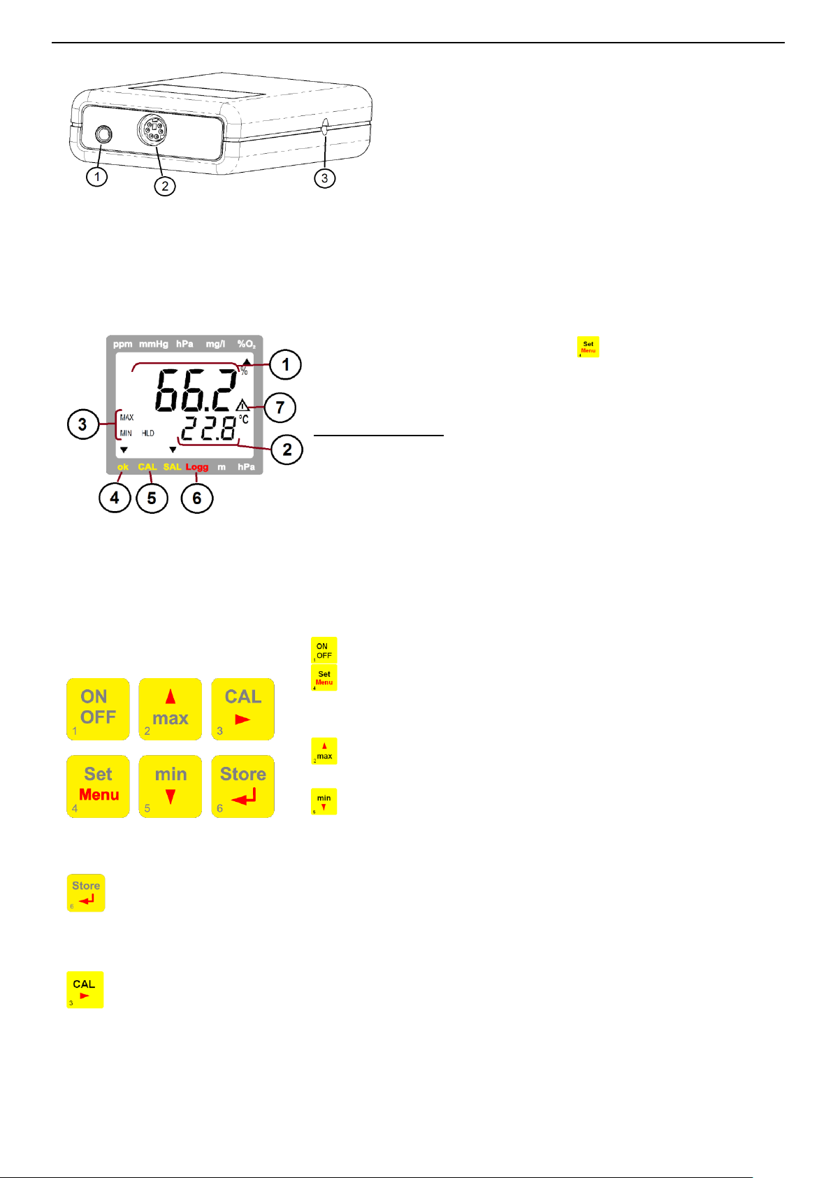
1.
Output: Operation as interface for t he connection of
galvanically isolated adapters (accessories: GRS
3100, USB 3100)
Attention: The mode of operation has to be
configured (p.r.t Chapter 5) and influences the power
consumption.
2.
Sensor connection MiniDIN
3.
Power supply: d.c.connector (internal pin Ø 1.9 mm) for external 10.5-12V direct voltage supply
1 = Main Display:
Possible displays:
Oxygen concentration in % (% O2 Vol)
Oxygen partialpressure (hPa or mmHg)
(change with -key)
2 = secondary
display:
Display of sensor temperature or absoute
pressure (alternating, please refer to Chapter
5. LcD.2)
Special elements:
3 = MIN/MAX/HLD:
Shows, if minimum/maximum/
memorized measuring value is in display
4 = ok-arrow:
Signals, if oxygen and temperature values
are stable
5 = CAL- arrow:
Signals, if automatic calibration is in
progress
6 = Logg - arrow
No function
7 = Warning sign:
Signals weak battery or other warning
message
Die restlichen Pfeile haben in dieser Gerätevariante keine Funktion
On / off key
Set/Menü
Press 2 sec.: (Menu): call configuration menu
Press shortly: Change the oxygen display unit
(please refer to chapter 5)
+
min/max when taking measurements:
press shortly: min. or max. measured oxygen value and
referring temperature and pressure values
will be displayed
press for 2 sec.: the min. or max. value will be deleted
Configuration: to enter values, or change settings
Store/Enter
- Measuring:
with Auto-Hold off: hold and save current measuring value (‘HLD’ is displayed)
with Auto-Hold on: start new measuring, It is finished , when “HLD’ shows in display
- Set/Menu: confirm settings, return to measuring
CAL:
press shortly: display of sensor state rating
press for 2 sec: start sensor calibration
4.4 Anschlüsse
4.5 Display elements
4.6 Pushbuttons

H74.0.14.6C-05 Operating Manual GMH 3692 page 6 of 12
Pop-up clip closed
Pop-up clip at position 90°
Pop-up clip at position 180°
Device attached to a belt
Device set up on a table
Device suspended from
magnetic holder
GMH 1300
1 2 3
4 5 6
ON
OFF
max
Store
CAL
min
Set
Menu Quit
1 2 3
4 5 6
ON
OFF
max
Store
CAL
min
Set
Menu Quit
CAL
CAL
max
CAL
max
Store
CAL
min
1 2 3
4 5 6
ON
OFF
max
Store
CAL
min
Set
Menu Quit
Store
CAL
4.7 Pop-up clip
Handling:
• Pull at label “open” in order to swing open the pop-up clip.
• Pull at label “open” again to swing open the pop-up clip further.
Function:
• The device with a closed pop-up clip can be plainly laid onto a table or attached to a belt, etc.
• The device with pop-up clip at position 90° can be set up on a table, etc.
• The device with pop-up clip at position 180° can be suspended from a screw or the magnetic holder
GMH 1300.
5 Configuration
Some menu points depend on current device settings.
To change device settings, press „Menu“ for 2 seconds. This will activate the configuration menu (main
display: “Set”). Pressing „Menu“ changes between the menus points, pressing jumps to the
referring parameters, which can be selected with key .
The parameters can be changed with or . Pressing „Menu“ again jumps back to the main
configuration menu and saves the settings. "Quit" finishes the configuration and returns to standard
measuring operation.

H74.0.14.6C-05 Operating Manual GMH 3692 page 7 of 12
Menu
Parameter
Value
Description
key Menu
key
key or
p.r.t
SET
(ONF
Set Configuration: General configurations
[H 2
P 02
hPa
Oxygen partial pressure display in hPa
*
P 02
mmHg
Oxygen partial pressure display in mmHg
LCD.2
T
Second. display always temperature
P
Second. display always absolute pressure
P T
Second. display alternates between temperature and abs. pressure
U N,T
T
°C
All temperatures in degree Celsius (ex works setting)
°F
All temperatures in degree Fahrenheit
[AL.P
1-PT
Simple one point calibration at air
2-PT
2 point calibration at air and 0% (e.g. N2 ) or 100 %
3-PT
2 point calibration at air and 0% (e.g. N2 ) and 100 %
[. INT
1 … 365
Calibration reminder period (in days)
OFF
No calibration reminder
A VTO
HLD
ON
Auto measuring value identification Auto Hold (when logger = off)
OFF
Standard hold function on key press (when logger = off)
P.OFF
1 … 120
Power-off delay in minutes. Device will be automatically switched off as
soon as this time has elapsed if no key is pressed/no interface
communication takes place. (ex works setting 20min)
OFF
Automatic power-off function deactivated (continuous operation)
ADR
0 1, 1 1,2 1, … 9 1
Base address for serial interface communication (ex works setting 01)
SET
(ORR
Set Corr: Input adjustment
0FFS
°C or °F
-5.0 °C .. 5.0 °C
or.
-9.0 °F .. 9.0 °F
The zero point of the temperature measuring is shifted for the entered
value.
This can be used to compensate sensor and instrument deviations
OFF
No zero adjustment for temperature measurement (=0.0°)
S[AL
°C or °F
-5.00 ... 5.00 %
The slope of the temperature measurement is corrected by this value.
This can be used to compensate sensor and instrument deviations
OFF
No slope adjustment for temperature measurement (=0.00)
0FFS
hPa
-20 .. 20 hPa
The zero point of the pressure measuring is shifted for the entered value.
This can be used to compensate sensor deviations
OFF
No zero adjustment for pressure measurement (=0.0°)
SET
AL
Set Alarm: Einstellung der Alarmfunktion
AL. 1
ON / NO.SO
Messkanal Sauerstoff: Alarm an mit Hupe / Alarm an ohne Hupe
OFF
keine Alarmfunktion für Messkanal Sauerstoff
AL.,N
[ONC
Alarmkanal Sauerstoff: Konzentration in %
P. 02
Alarmkanal Sauerstoff: Partialdruck in hPa oder mmHg
A 1.LO
z.B. 0.0..100.0 %
Min-Alarm-Grenze Sauerstoff (nicht bei AL. 1. oFF)
A 1.H,
z.B. 0.0..100.0 %
Max-Alarm-Grenze Sauerstoff (nicht bei AL. 1. oFF)
AL. 2
ON / NO.SO
Alarm Temperaturmessung an mit Hupe / Alarm an ohne Hupe
OFF
keine Alarmfunktion für Temperaturmessung
A2.LO
-5.0 ..+ 50.0 °C
Min-Alarm-Grenze Temperatur (nicht bei AL. 2. oFF)
A2.H,
-5.0 ..+ 50.0 °C
Max-Alarm-Grenze Temperatur (nicht bei AL. 2. oFF)
Pressing “menu” and “store” at the same time for more than 2 seconds will reset the device to
factory defaults
If no key is pressed within 2 minutes the configuration will be aborted. All changes will not be saved!

H74.0.14.6C-05 Operating Manual GMH 3692 page 8 of 12
6 Oxygen Measuring in Gases- Please Note
The GMH 369x is designed for measuring the oxygen partial pressure or the oxygen concentration (%vol,
calculated from partial pressure and ambient pressure) in gases. Please keep in mind:
The sensor hast o calibrated regularily, e.g. at fresh ambient air
The calibration and the measuring are pressure depending!
The instrument automatically measures the ambient pressure, be sure, that instruments pressure is
the same like the pressure at the sensors membrane. For the full automatic compensation a precision
pressure sensor is integrated in the instrument.
The sensor temperature has to be the same like the gas temperture!
Temperature differences may falsify the results!
Please have in mind that temperature adoption of the sensor and the air may take several hours.
A suitable ventilation or gasflow around the sensor would speed up this process significantly.
The sensor consists of a sensing element (GOEL xxx) enclose in a sensor housing (GGO/ GGA/GOO).
When purchasing a Sensor GGO/GGA/GOO xxx, a sensor element is already integrated, e.g. a GGO 370:
contains housing GGO and a sensor element GOEL 370.
6.1 Choice of Sensing Elements#
GOEL 370:
Universal sensor element with special protection measures especially for diving application (“Nitrox”).
Very long life time, also suitable for application with larger CO2 concentrations.
GOEL 380:
Fast responding for low oxygen concentration e.g. protection atmosphere below 1%, max 25%.
For application without larger CO2 concentration.
Sensors are not allowed to used in „under-Water-Diving-Application (e.g. Rebreather)
DANGER
6.2 Application of the different sensor types GGO ..., GOO ... and GGA
GGO (closed sensor)
For measurements at atmosphere and in systems without over or under pressure the GGO... is sufficient.
Additionally the GGO can be screwed tightly into systems with small over or under pressure.
Attention! Mind the maximum pressure and the maximum pressure difference at the membrane.
If instrument and sensor pressure are different, it will be compensated wrong!
GOO 370 / 380 (open sensor)
The sensor is equipped with drillings at the end and because of its special construction the measuring gas
streams optimally around the sensor. No pressure can appear while gas blows to the sensor, which
otherwise would result in erroneous measures. The temperature compensation speed of the sensor also is
optimised by this design.
Especially the measuring of gases from compressed gas bottles, where the expansion of the gas
leaving the bottle lowers the temperature, is optimised with regard to the temperature compensation and
pressure errors. The gas flow should be chosen in a suitable range, where no overpressure can happen,
esp. if the sensor is connected directly to the source e.g. by means of a tube.
GGA (closed sensor with pressure port)
Not suitable for GMH 3692
H74.0.14.6C-05 Operating Manual GMH 3692 page 9 of 12
7 Calibration of the Sensor
In order to compensate for ageing of the sensor, the sensor has to be calibrated at regular intervals.
The device is equipped with an easy-to-use calibration functions.
We recommend to calibrate the sensor at least all 7 days, or to get maximum precision, before each
measuring series.
7.1 One Point Calibration ('(AL 1-PT')
The calibration adjusts the sensor to the oxygen content of the atmosphere (20.95%). Therefore simply
expose the sensor to the ambient air (sufficient ventilation in closed rooms has to be ensured)
Start calibration: press -key for 2 seconds
The display will show 'A,R , and as soon the values for oxygen and temperature are stable, the
calibration will be finished
Then the electrode state resulting of the successful calibration will be shown for a short time (evaluation in
10% steps: xx% ELE[).
7.2 2 / 3-Point Calibration ('(AL 2-PT, (AL 3-PT')
The sensor will be automatically calibrated to the oxygen content of the atmosphere (20.95%) and one or two
additional concentrations. As reference gases usually Nitrogen (0% vol O2) or pure oxygen are used
1. Start calibration: press -key for 2 seconds
2. First calibration reference: (Pt.1)
As first reference at a 3-point calibration, the zero reference has to be applied (NULL),
at a 2-point calibration either 100% or 0%(NULL).
The display will show , and the referring reference which should be applied:
- NULL for 0% oxygen
- 0.2 for pure oxygen
As long as the display blinks, no valid reference is recognised by the instrument.
As soon the values for oxygen and temperature are stable, the calibration of the first point will be finished.
The instrument tells you to apply the next reference (possible references are blinking in the display).
3. Second calibration reference: (Pt.2)
The display will show , and the referring reference which should be applied:
- A,R for ambient air
- 0.2 for pure oxygen
- NULL for 0% oxygen
As long as the display blinks, no valid reference is recognised by the instrument.
As soon the values for oxygen and temperature are stable, the calibration of the second point will be
finished. At 2-point calibration the calibration will be finished and the electrode state resulting of the
successful calibration will be shown for a short time (evaluation in 10% steps: xx% ELE[).
At 3-point calibration the instrument tells you to apply the next reference (possible reference is blinking)
4. Third calibration reference: (Pt.3)
The display will show , and the referring reference which should be applied:
As soon the values for oxygen and temperature are stable, the calibration of the second point will be
finished. At 2-point calibration the calibration will be finished and the sensor state resulting of the successful
calibration will be shown for a short time (evaluation in 10% steps: xx% ELE[).
In case of error messages being displayed during the calibration process, please refer to our notes
at the end of this manual! If a calibration cannot be carried out after an extended period of time, at
least one of the measuring values is unstable (oxygen partial pressure, temperature).
Please check your measuring arrangements!
7.3 Evaluation of Sensor State (ELE[)
Watch sensor state: press key "CAL" shortly once display show for a short time xx% ELE[.
It will show the electrode state resulting of the last successful calibration carried out.
The valuation is displayed in 10 percent steps: 100% means optimal sensor condition. Lower values are
indicating that the sensor life time will be reached soon.
Remark: But also an erroneous pressure may be the cause of low valuation values.

H74.0.14.6C-05 Operating Manual GMH 3692 page 10 of 12
1 2 3 4 Code
Name/Function
1 2 3 4 Code
Name/Function
x x x x 0
read nominal value
x x x x 199
read measuring type in display
x x x x 3
read system status
x x x x 200
read min. display range
x 12
read ID-no.
x x x x 201
read max. display range
x x x 22
read min alarm limit
x x x x 202
read unit of display
x x x 23
read max alarm limit
x x x x 204
read decimal point of display
x x x x 176
read min measuring range
x 208
read channel count
x x x x 177
read max measuring range
x 222
read turn-off-delay
x x x x 178
read measuring range unit
x 223
Set turn-off-delay
x x x x 179
read measuring range decimal point
x 240
Reset
x x x x 180
read measuring type
x 254
read program identification
7.4 Calibration Interval ([.INT)
You can enter the interval after which the device reminds you to recalibrate in the configuration.
The interval times should be chosen according to the application and the stability of the sensor.
“CAL” flashes on the display as soon as the interval has expired.
8 Inspection of the accuracy / Adjustment Services
The instrument can be sent to the manufacturer for adjustment and function test.
Only the manufacturer can check all systems on correct them if necessary.
Calibration certificates – DKD-certificates – other certificates:
If device should be certificated for its accuracy, it is the best solution to return it to the manufacturer.
(please specify references, e.g. 20.9 and 100%).
If the instrument is certified with its sensor, this proves for example the linearity of the measuring chain,
regular recalibration by the user is still necessary!
9 Serial Interface
With an electrically isolated interface converter USB3100, GRS3100 or GRS3105 (accessory) the device can
be connected to a PC.
With the GRS3105 it is possible to connect up to 5 instruments of the GMH3000 family to a single interface
(please also refer to GRS3105-manual). As a precondition the base addresses of all devices must not be
identical, make sure to configure the base addresses accordingly (refer menu point “Adr.” in chapter 5).
In order to avoid transmission errors, there are several security checks implemented (e.g. CRC).
The following standard software packages are available for data transfer:
GSOFT3050: Operating and evaluation software for instruments with integrated logger function
EBS20M/ -60M: 20- / 60-channel software to record and display the measuring values
GMHKonfig: Software for a comfortable configuration of the device (e.g. freeware)
In case you want to develop your own software we offer a GMH3000-development package including
- an universally applicable 32bit Windows functions library ('GMH3000.DLL') with documentation that can
be used by all 'serious' programming languages.
- Programming examples for Visual Studio 2010 (C#, C++), Visual Basic 6.0™, Delphi 1.0™, Testpoint™,
Labview™
The Device has 4 Channels:
- oxygen concentration % Vol
- oxygen partial pressure in hPa or mmHg
- temperature value at the time of recording in °C or °F
- absolute pressure in hPa abs or mmHg abs
Supported Interface-functions:
The measuring and range values read via interface are always in the selected display unit!
10 Alarm („AL.“)
There are three possible settings:
Alarm off (AL. oFF), on with buzzer (AL. on), on without buzzer (AL. no.So).
Following conditions will display an alarm, when the function is activated (on or no.So):
- Value is below lower (AL. Lo) or above upper alarm rail (AL.Hi).
- Sensor error
- Low battery (bAt)
- Err.7: System error (always with buzzer)
In case of an alarm and when polling the interface the “prio”-flag is set in the returned message.

H74.0.14.6C-05 Operating Manual GMH 3692 page 11 of 12
Display
Meaning
Remedy
low battery voltage, device will continue to work
for a short time
replace battery
If mains operation: wrong voltage
replace power supply, if fault continues to
exist: device damaged
low battery voltage
replace battery
If mains operation: wrong voltage
Check/replace power supply, if fault
continues to exist: device damaged
No display
or
weird display
Device does not
react on keys
low battery voltage
replace battery
If mains operation: wrong voltage
check/replace power supply, if fault
continues to exist: device damaged
system error
disconnect battery or power supply, wait
some time, re-connect
device defective
return to manufacturer for repair
SENS
ERRO
sensor error: no sensor cable connected
connect suitable sensor
Sensor, cable or instrument defect
return to manufacturer for repair
ERR.1
Value exceeding measuring range
Check: Is the value exceeding the
measuring range specified? ->value too
high!
Wrong sensor connected
Check sensor
Sensor, cable or instrument defect
return to manufacturer for repair
ERR.2
Value below display range
Check: Is the value below the measuring
range specified? ->value too low!
Wrong sensor connected
Check sensor
Sensor, cable or instrument defect
return to manufacturer for repair
ERR.7
system error
return to manufacturer for repair
>CAL<
CAL flashing in
display
either preset calibration interval has expired or
last calibration is not valid
device has to be calibrated!
[AL ERR.1
wrong reference point at air
check sensor and reference gas
[AL ERR.2
slope too low
reference gas wrong
check sensor and reference gas
sensor element is defect
replace sensor element
[AL ERR.3
slope too high
reference gas wrong
check sensor and reference gas
sensor element is defect
replace sensor element
[AL ERR.4
incorrect calibration temperature
calibration can only be done at 0…50 °C
[AL ERR.5
Zero value to low/negative
sensor element is defect
replace sensor element
[AL ERR.6
zero value to high
reference gas wrong
check sensor and reference gas
sensor element is defect
replace sensor element
[AL ERR.7
incorrect calibration pressure
check calibration pressure
[AL ERR.8
signal not stable / timeout
check sensor and reference gas
[AL ERR.9
sensor not known: cannot be calibrated
check sensor and wiring
11 Error and System Messages
If “BAT“ is flashing, the battery will be exhausted soon. Further measurements are possible for short time.
If “BAT“ is displayed continuously the battery is ultimately exhausted and has to be replaced. Further
measurements aren’t possible any more.
Messages During Calibration/Adjustment

H74.0.14.6C-05 Operating Manual GMH 3692 page 12 of 12
Measuring ranges
Oxygen concentration
0.0 ... 100.0 % O2 (Vol)
electrochemical sensors GGO / GOO
Oxygen partial pressure
0 ... 1100 hPa O2
“ “ “
Sensor temperature
-5.0 ... + 50.0 °C
NTC 10k (integr. in GGO / GOO cable)
Absolute pressure
10 ... 1200 hPa abs.
integrated pressure sensor
Accuracy
(instrument without
sensor, at 25°C, 1000
hPa abs)
Oxygen concentration
±0.1 % O2 (Vol)
Oxygen partial pressure
± 1 hPa
Sensor temperature
± 0.1 °C
Accuracy
Absolute pressure
3 hPa or 0.1% of measured value (the higher one to be applied)
Working conditions
-20 ... 50 °C; 0 ... 95 % r.H. (not condensing)
Nom. temperature
25°C
Storage temp.
-20 ... 70 °C
Connections
O2 & temperature
6 pole Mini-DIN Socket
Interface /
serial, (3.5mm audio plug),via isolated adapter GRS3100, GRS3105 or
USB3100 (accessories) for PC-USB or RS232- connection
external supply
d.c. connector (diameter of internal pin 1.9 mm) for external 10.5-12V
direct voltage supply. (suitable power supply: GNG10/3000)
Display
4 digit 7-segment 2 lines, additional segments
Calibration
automatic
1 -, 2- or 3-point calibration,
0%, 100% or ambient air (20.95%)
GLP
adjustable calibration intervals (1 to 365 days, CAL warning after
expiration)
Alarm
Buzzer / visual / interface
2 channels: selectable oxygen unit and temperature
Additional functions
Min / max / hold / auto hold
Housing
Break-proof ABS housing
Protection class
Front side IP65
Dimensions L*B*H [mm]
Weight
Without pressure port: 142 x 71 x 26 mm (L x B x H)
approx. 160 g (incl. battery)
Power supply
Current consumption
9V-Battery, Type IEC 6F22 (in scope of supply) or external supply
Ca. 0.6 mA (if Out = Off ca. 0.4mA)
Change battery indicator
Automatic at weak battery and ’ bAt ’
Auto-Off-Function
Device will be automatically switched off if no key is pressed/no
interface communication takes place for the time of the power-off delay.
The power-off delay can be set to values between 1and 120 min.; it can
be completely deactivated.
EMI
The device corresponds to the essential protection ratings established in
the Regulations of the Council for the Approximation of Legislation for
the member countries regarding electromagnetic compatibility
(2004/108/EG). Additional fault: <1%
Dispense exhausted batteries at destined gathering places.
This device must not be disposed as “residual waste”. To dispose this device, please send it
directly to us (adequately stamped). We will dispose it appropriately and environmentally friendly.
DANGER
All devices returned to the manufacturer have to be free of any residual of measuring media and
other hazardous substances. Measuring residuals at housing or sensor may be a risk for persons
or environment
Use an adequate transport package for reshipment, especially for fully functional devices. Please
make sure that the device is protected in the package by enough packing materials.
12 Specification
13 Reshipment and Disposall

H36.0.13.6C-07
GMH 3691 GOG
For quick and cost-effective measurement of residual oxygen,
check-up of protective atmosphere in food packagings and for selective “sniffing”
Scope of supply:
1 display instrument GMH3691
2 hand pump (compress to use, the hand pump automatically
draws in the measuring gas after release, period of drawing
about 30 seconds)
3 GOG oxygen sensor with penetration needle,
optimised for quick measurement of tiniest amounts of
gases
Checking the calibration:
In order to get the optimum precision of the measurings, we suggest to check the calibration before each
measuring. This check is done at normal ambient air.
Before the check or calibration, the sensor’s temperature has to be adjusted to the ambient temperature.
In order to optimise the operational readiness of the instrument it is good practice to store it directly at the
location, were the measurings should be made.
For the check of the calibration the protection cap of the needle has to be removed. Compress the hand
pump (while the instrument is switched on) and release it afterwards. Then, already after 10 seconds the
display should show a oxygen content of 20.9 ... 21.0%. If there are greater deviations we suggest to
calibrate the instrument according to the manual GMH3691 (chapter: Calibration of the oxygen sensor).
The Measuring:
Preparation / Recommendations
Before measuring we recommend to put a rubber foam sticker onto the package.
(see illustration on the right hand side).
The sticker prevents the package from tearing up due to the penetration of the
needle. Furthermore it prevents a gap between package and needle, no ambient
air can flow in. This would corrupt the measuring.
This is especially important for the accuracy of the measurement of packages with little gas volume.
GREISINGER electronic GmbH Hans-Sachs-Straße 26 Tel.: 0049 9402 / 9383-0 http://www.greisinger.de
D-93128 Regenstauf Fax: 0049 9402 / 9383-33 Email: info@greisinger.de

H36.0.13.6C-07
Measuring:
1. Penetrate the rubber foam sticker until the needle hits a hollow space of the package.
Attention: You must take care not to draw foodstuffs in, because otherwise the needle can
be blocked and the sensor can be contaminated.
2. Compress the hand pump completely. A valve prevents air from flowing into the package due to the
compression of the hand pump.
3. After releasing it, the pump draws the measuring gas out of the packing for ~30 seconds.
After been compressed, the
hand pump draws in for
approx. 30 seconds.
The intake / measuring can
be continued by compress the
pump again.
Compressed hand pump Uncompressed hand pump
4. The oxygen contents can read off the display already after ~10 seconds.
Note: You can only read off a valid measured value while the hand pump is drawing.
The pump can be compressed several times while connected to the same package, a reverse valve
prevents air from flowing into the package due to the compression of the hand pump, that would falsify the
measured value.
Flushing the sensor:
The measuring system must flushed with ambient air after the measuring.
Compress therefore the hand pump for 1 or 2 times.
Measuring accuracy and calibration
You could carry out a two-point-calibration of the GMH 3691 in order to get absolute precise measured
values. Therefore a second reference point - besides air- is required.
We recommend to use N2 if you want to check-up on the residual oxygen content in food packaging filled
with protective atmosphere. N2 is available in bottles and is equivalent to 0.0% oxygen.
The type of the calibration has to be selected in the device menu before calibrating.
If the whole system is carefully calibrated and the measuring will done accurately the accuracy of
measurement will be:
1 point calibration: ± 0.2% O2 ± 1digit at concentrations <10% O2
2 point calibration: ± 0.1% O2 ± 1digit at concentrations <10% O2
For information to the 2-point calibration please refer to the GMH3691 operating manual.
The measuring system is optimised for needle with ∅0.9mm. By needles with less diameter the needed
gas volume can be reduced further. But the measuring value will be lowered by the resulting under
pressure. (up to 40mbar at Ø0.45mm)
Example: 40mbar under pressure at 1000 mbar ambient pressure:
(1000-40)/1000 * 20.9% -> display 20.1%.
For measuring of protective atmosphere this error can be neglected (Example display of 1.9% instead 2.0%).
GREISINGER electronic GmbH Hans-Sachs-Straße 26 Tel.: 0049 9402 / 9383-0 http://www.greisinger.de
D-93128 Regenstauf Fax: 0049 9402 / 9383-33 Email: info@greisinger.de
 Loading...