

Page 1
H33.0.02.6C-09
Measuring device for pH / Redox
temperature
as of version V2.6 Operating Manual GMH 3530
GREISINGER electronic GmbH
D - 93128 Regenstauf, Hans-Sachs-Straße 26
+49 (0) 9402 / 9383-0 +49 (0) 9402 / 9383-33 info@greisinger.de
Page 2

H33.0.02.6C-09 Operating Manual GMH 3530 page 2 of 14
Index
MEASURING DEVICE FOR PH / REDOX TEMPERATURE .................................................................................. 1
1 DESIGNATED USE ................................................................................................................................................. 2
2 GENERAL NOTE .................................................................................................................................................... 2
3 OPERATING AND MAINTENANCE ADVICE: ....................................................................................................... 3
4 SAFETY REQUIREMENTS: ................................................................................................................................... 3
5 DISPLAY AND CONTROL ELEMENTS ................................................................................................................. 4
5.1 DISPLAY ELEMENTS ............................................................................................................................................ 4
5.2 PUSHBUTTONS ................................................................................................................................................... 4
5.3 CONNECTIONS .................................................................................................................................................... 4
6 CONFIGURATION .................................................................................................................................................. 5
7 MANUAL SETTING OF TEMPERATURE WHEN OPERATING DEVICE WITHOUT TEMPERATURE PROBE 6
8 MANUAL SETTING OF PH-VALUE FOR MEASURING FUNCTION RH ............................................................. 6
9 CALIBRATION OF ’PH’-MEASUREMENT ............................................................................................................ 6
9.1 HOW TO PREPARE CALIBRATION SOLUTIONS OF STANDARD SERIES ........................................................................ 7
9.2 NOTE: AUTOMATIC TEMPERATURE COMPENSATION DURING CALIBRATION.............................................................. 7
9.3 HOW TO CARRY OUT CALIBRATION ....................................................................................................................... 7
10 INDICATION OF ELECTRODE STATE (FOR PH-MEASUREMENTS ONLY) .................................................. 9
11 HOW TO PERFORM A RH-MEASUREMENT .................................................................................................... 9
12 ERROR AND SYSTEM MESSAGES ................................................................................................................ 10
13 THE PH-ELECTRODE ...................................................................................................................................... 11
13.1 VARIOUS APPLICATIONS REQUIRE SPECIAL ELECTRODES ................................................................................. 11
14 THE REDOX-ELECTRODE ............................................................................................................................... 12
15 THE SERIAL INTERFACE ................................................................................................................................ 13
15.1 THE FOLLOWING INTERFACE FUNCTIONS WILL BE SUPPORTED:......................................................................... 13
15.2 FUNCTIONS FOR THIS DEVICE ONLY (DLL-248) ............................................................................................... 13
16 SPECIFICATION: .............................................................................................................................................. 14
17 DISPOSAL INSTRUCTION: .............................................................................................................................. 14
1 Designated Use
This device is designed for the measurement of pH and redox potentials. Therefore a suitable electrode is needed.
The electrode is connected via BNC-socket.
Please note: You need different types of electrodes for pH and redox measurement.
Additionally a temperature probe can be connected (Pt100, with suitable MINI-DIN plug).
This enables the automatic temperature compensation (ATC) for pH measurements.
The temperature of the measured solution can also be displayed. .
2 General Note
Read this document carefully and get used to the operation of the device before you use it. Keep this document
within reach for consulting in case of doubt.
Page 3

H33.0.02.6C-09 Operating Manual GMH 3530 page 3 of 14
3 Operating and Maintenance Advice:
a) When to replace battery:
If and ´bAt´ are shown in the lower display the battery has been used up and needs to be replaced. The device will, however, operate correctly for a certain time.
If ´bAt´ is shown in the upper display the voltage is too low to operate the device; the battery has been completely
used up.
Please note: The battery has to be taken out, when storing device above 50°C.
We recommend to take out battery if device is not used for a longer period of time.
b) Treat device and sensor carefully. Use only in accordance with above specification. (do not throw, hit against etc.).
Protect plug and socket from soiling.
c) When connecting the temperature probe the connector may not lock to the jack correctly. In such a case hold the
connector not at the case but at the buckling protection of the cable during the plug in. Don’t connect electrode
canted! If plug is entered correctly, it will slide in smoothly.
To disconnect temperature probe do not pull at the cable but at the plug.
If plug is entered incorrectly the connecting pins of the plug can be damaged. => Plug can no longer be used and
connecting cable needs to be replaced.
d) Mains operation:
When using a power supply device please note that operating voltage has to be 10.5 to 12 V DC.
Do not apply overvoltage!! Cheap 12V-power supply devices often have excessive no-load voltage. We, therefore, recommend using regulated voltage power supply devices. Trouble-free operation is guaranteed by our
power supply devices. Trouble-free operation is guaranteed by our power supply, GNG10/3000.
Prior to connecting the plug power supply device with the mains supply make sure that the operating voltage
stated at the power supply device is identical to the mains voltage.
e) Display values for damaged electrode cable or if no pH or redox-electrode has been connected
If no electrode is connected or the connection cable is damaged the display will nevertheless show mV, pH or rH
values. Please note that these values can never be correct measuring results!
4 Safety Requirements:
This device has been designed and tested in accordance with the safety regulations for electronic devices.
However, its trouble-free operation and reliability cannot be guaranteed unless the standard safety measures and
special safety advises given in this manual will be adhered to when using the device.
1. Trouble-free operation and reliability of the device can only be guaranteed if the device is not subjected to any
other climatic conditions than those stated under "Specification".
2. If the device is transported from a cold to a warm environment condensation may cause in a failure of the function. In such a case make sure the device temperature has adjusted to the ambient temperature before trying a
new start-up.
3. If device is to be connected to other devices (e.g. via serial interface) the circuitry has to be designed most carefully. Internal connection in third party devices (e.g. connection GND and earth) may result in not-permissible voltages impairing or destroying the device or another device connected.
Warning: If device is operated with a defective mains power supply (short circuit from mains voltage to output
voltage) this may result in hazardous voltages at the device (e.g. sensor socket, serial interface).
4. If there is a risk whatsoever involved in running it, the device has to be switched off immediately and to be
marked accordingly to avoid re-starting.
Operator safety may be a risk if:
- there is visible damage to the device
- the device is not working as specified
- the device has been stored under unsuitable conditions for a longer time.
In case of doubt, please return device to manufacturer for repair or maintenance.
5. Warning: Do not use these products as safety or emergency stop devices or in any other application where failure
of the product could result in personal injury or material damage.
Failure to comply with these instructions could result in death or serious injury and material damage.
.
Page 4
H33.0.02.6C-09 Operating Manual GMH 3530 page 4 of 14
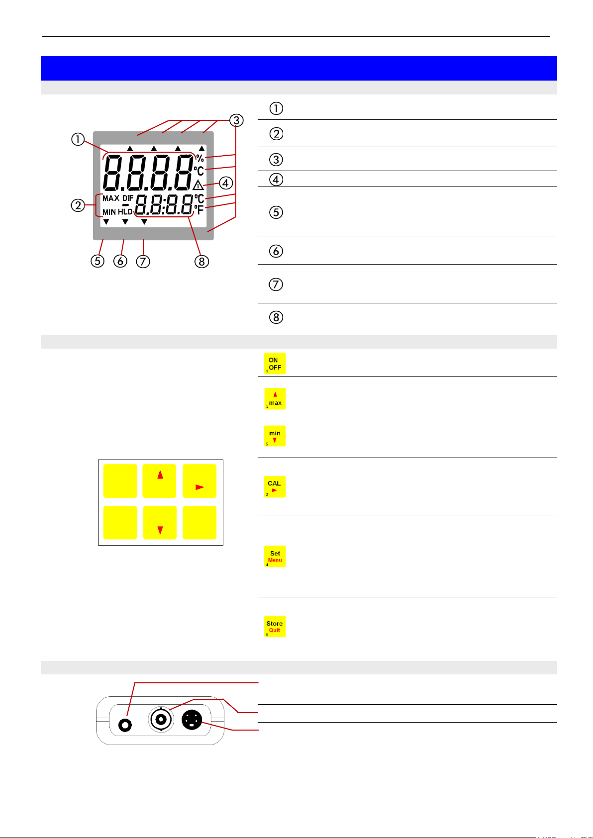
Main display: pH-value, redox-value (mV, mVH), rH
value or user prompt
Display elements to show minimum/maximum/
memorized measuring value
Display of measuring units
Warning signal (low battery or recalibration prompt)
ATC-arrow: indicates if temperature sensor has been
connected, i.e. if automatic temperature
compensation is active, when operating in
the pH, mVH or rH mode.
ok-arrow: indicates that measuring value has been sta-
ble for a longer period of time
CAL-arrow: indicates that device is being calibrated at
the moment, when operating in the pH
mode.
Secondary display: measuring value, temperature
or user prompt
On/off key
+
min/max when taking measurements:
press shortly: min. or max. meas. value so far will be
displayed
press for 2 sec.: the min. or max. value will be deleted
Configuration: to enter values, or
change settings
CAL: for ’pH’ mode only:
press shortly: display state of electrode condition and
calibration data
press for 2 sec: start pH-calibration
Set/Menu:
press (Set) shortly: for ’pH’ and ’mVH: manual tempera-
ture input if no temperature probe is con-
nected additionally for ’rH’: manual input of
pH value.
press (Menu) for 2 sec: configuration will be activated
Store/Quit:
measuring: holds and memorizes current meas. value
(’HLD’ in display)
Configuration: enter setting, return to measuring
interface: connection for galv. Isolated interface adapter
(accessory: GRS 3100, GRS3105 or USB3100)
BNC-socket: connection for pH- or redox-electrode
Mini-DIN-socket: connection for Pt100-temperature probe
(4-wire connection; 2-wire also possible, but may result in additional measuring faults due to cable)
The mains socket is located at the left side of the instrument
1 2 3
4 5 6
ON
OFF
max
Store
CAL
min
Set
Menu Quit
pHmV mV
H
rH
ATC ok CAL AL Logg pH
mbar
5 Display and control elements
5.1 Display elements
5.2 Pushbuttons
5.3 Connections
Page 5
H33.0.02.6C-09 Operating Manual GMH 3530 page 5 of 14
pH:
pH-measurements with pH-electrode
mV:
redox measurements with redox-electrode
mVH:
redox measurement with redox-electrode (with standard 3 mol/l KCL electrolyte).
The value shown is corrected to the standard hydrogen system (0 - 50°C:
acc. to DIN 38404).
Temperature probe (ATC) or manual temperature input required.
rH:
rH-measurement: the rH value is calculated from the measured values of
pH, redox and temperature. You may also enter pH and temperature values manually.
thEr:
Pt100 thermometer: the current temperature is displayed in the main display, the secondary display either shows the min. or max. value or is used
for the hold-function.
2-Pt:
the pH-electrode will be calibrated at 2 points (one calibration point in
neutral range and one calibration point in acid or basic range)
3-Pt:
the pH-electrode will be calibrated at 3 points (one calibration point in
neutral, acid and basic range)
°C
All temperature values in degree Celsius
°F:
All temperature values in degree Fahrenheit
-10.0°C ... 10.0°C
or
-18.0°F ... 18.0°F
The zero point of the temperature measurement will be displaced by this value to compensate for deviations in the
sensor and measuring device:
temperature displayed = temperature measured - offset
off:
Zero shift has been deactivated (=0.0°)
1...120:
Power-off delay in minutes. Device will be automatically switched off as
soon as this time has elapsed if no key is pressed/no interface communication takes place.
off:
Automatic power-off function deactivated (continuous operation, e.g. for
mains operation)
pHmV mV
H
rH
ATC ok CAL AL Logg pH
mbar
max
min
2
5
pHmV mV
H
rH
ATC ok C AL AL Logg pH
mbar
max
min
2
5
pHmV mV
H
rH
ATC ok CAL AL Logg pH
mbar
max
min
2
5
ᄚC
pHmVmV
H
rH
ATC ok CAL AL Logg pH
max
min
2
5
pHmV mV
H
rH
ATC ok CAL AL Logg pH
mbar
max
min
2
5
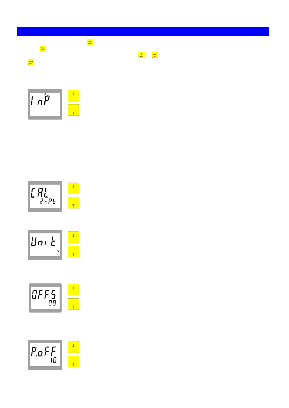
6 Configuration
To configurate the device press -key for 2 seconds.
Press the -key again to choose between the individual values that can be set.
The individual values are changed by pressing the keys or .
Use to leave configuration menu and save your settings.
’Input’: Selection of Measuring Function pH / Redox mV / Redox mVH / rH / thEr
The current measuring function can be identified by an arrow at the top of the display:
’CAL’: Selection of Number of Calibration Points (for pH measurements only)
’Unit’: Selection of Temperature Unit °C /°F
’Offset’: Zero Shift of Temperature
Note: If the temperature offset is set, this is displayed when the device is turned
on.
’Power.off’: Selection of Power-off Delay
Page 6

H33.0.02.6C-09 Operating Manual GMH 3530 page 6 of 14
01, 11, 21, ..., 91:
Base address for interface communication. Channel 1 will
be addressed by the base address set, channel 2 and 3 will
have the following addresses.
(Example: base address 21 - channel 1 = 21, channel 2 =
22, channel 3 = 23)
0 ... 105 °C:
Input of temperature of liquid
0.0 … 14.00 pH:
Input of pH-value
pHmVmV
H
rH
ATC ok CAL AL Logg pH
max
min
2
5
pHmV mV
H
rH
ATC ok CAL AL Logg pH
mbar
max
min
2
5
pHmV mV
H
rH
ATC ok CAL AL Logg pH
mbar
max
min
2
5
’Address’: Selection of Base Address
Using the interface converter GRS3105 it is possible to connect several devices to a single interface. As a precondition the base addresses of all devices must not be identical. In case several devices are connected via one interface
make sure to configurate the base addresses accordingly.
7 Manual Setting of Temperature
when operating device without temperature probe
When operating in pH, mVH or rH mode, the device requires the temperature of the liquid being measured.
We recommend using a temperature probe (which will be automatically detected); the measured temperature will be
used to calculate the measuring values (ATC: automatic temperature compensation).
If no temperature probe is connected, temperature may be entered manually:
To do so press the -key shortly.
Use the -key to acknowledge input; device returns to measuring mode.
8 Manual Setting of pH-Value for measuring function rH
Running the GMH 3530 in the rH-measuring mode requires both temperature and pH value. Press shortly again
to switch over to the pH-value entering mode:
Use -key to acknowledge input and to return to measurement.
9 Calibration of ’pH’-Measurement
The electrode data of pH-electrodes are subject to a lot of fluctuation due to ageing and manufacturing tolerances.
Therefore it is necessary to check the calibration with buffer solutions before measurements take place. If deviations
are too large, a recalibration is necessary.
Buffer solutions are liquids with an accurate pH-value. The following buffers can be used for calibration:
- Standard-series (4.01pH, 7.00pH and 10.01pH)
- DIN-series (1.68pH(A), 4.01pH(C), 6.87pH(D), 9.18pH(F) and 12.45pH(G))
- Any buffer (neutral buffer ranging from 6.5 ... 7.5pH)
Service life of a buffer solution is limited and will be further reduced unless the electrodes are properly rinsed and dried
when changing over the solutions. This may even result in incorrect calibration! We recommend to use new buffer solution for calibration, as far as possible, and to rinse with non-ionising or distilled water.
Page 7

H33.0.02.6C-09 Operating Manual GMH 3530 page 7 of 14
Standard-series (values at 25°C: 4.01pH, 7.00pH, 10.01pH)
neutral calibration solution 7.00pH
DIN-series (values at 25 °C: 1.68 pH (A), 4.01 pH (C), 6.87 pH (D),
9.18 pH (F),12.45 pH (G) )
neutral calibration solution 6.87pH
manual buffer setting
If other buffers are used than those provided in the standard or DIN series select manual buffer setting now:
6.50 ... 7.50 pH: Setting range for neutral calibration solution
(please note, see above:
’Automatic temperature compensation during calibration’)
pHmV mV
H
rH
ATC ok CAL AL Logg pH
mbar
pHmV mV
H
rH
ATC ok CAL AL Logg pH
mbar
pHmV mV
H
rH
ATC ok CAL AL Logg pH
mbar
max
min
2
5
9.1 How to prepare calibration solutions of standard series
- Fill 2 plastic bottles with 100 ml distilled water each.
- Open pH 7 capsule (green) carefully (turn one half of the capsule while pulling and make sure not to spill any solution); put content (including both capsule parts) into one of the bottles.
- Put content of pH 4 capsule (orange) (or pH 10, blue) and both capsule parts into the second bottle.
The capsule shell will colour the liquid in the respective colour: orange = pH4.01; green = pH7.00; blue = pH10.01
Make sure to prepare buffer solutions in time as they can only be used after at least 3 hours. Shake well before use.
9.2 Note: Automatic temperature compensation during calibration
Both the signal of the pH-electrode and the pH-buffer are depending on temperature. If a temperature probe is connected, the temperature influence of the electrode is compensated automatically during measuring as well as during
calibration. Otherwise enter actual buffer temperature as accurate as possible (see below). When working with the
standard or DIN-buffer series, the influences of buffer temperature are also compensated. If buffers
are entered manually, make sure to enter the pH-values of the buffers at the relevant temperature to ensure optimum calibration of the device.
9.3 How to carry out calibration
Please note: the calibration can only carried out at a temperature range of 0 - 60°C !
If you have not yet done so set device to measuring mode ’pH’ (see configuration). Make sure that either the 2 or 3
point calibration (whichever is required) has been activated in the configuration.
Carefully remove electrode safety cap (Attention! Contains 3 mol KCl!).
Rinse electrode with distilled water and dry.
How to start calibration: press -key for 2 sec.
The display will prompt you to measure the first calibration solution. Use -key to abort calibration. In such a case
the last calibration before this one remains valid.
1. Selection of calibration solution
Use -key to switch over between the various series:
Note: The calibration procedure with buffers of standard series and with a temperature sensor used is
indicated by a green background.
Page 8

H33.0.02.6C-09 Operating Manual GMH 3530 page 8 of 14
Place electrode and temperature probe (if any) in the neutral solution stirring
gently.
The measuring value is stable as soon as the display stops blinking and the
’ok’-arrow is displayed in the left-hand corner of the display. Use -key to take
over meas. value.
The next calibration step will be displayed.
no temperature sensor: manual input of temperature of solution 1
Use or -key to enter the temperature of the buffer solution.
Use to take over the value and to display the next calibration step.
Place electrode and temperature probe (if any) in the buffer solution you want to
use for the next calibration point (e.g. for standard series: 4.01pH or 10.01pH).
In case of manual buffer selection use and -keys to enter pH-value of
the solution. If solutions of the Standard and DIN-series are used, their pHvalue will be automatically detected.
The measuring value is stable as soon as the display stops blinking and the
’ok’-arrow is displayed in the left-hand corner of the display. Use -key to take
over meas. value.
If no temperature probe is used the next calibration step will be displayed, otherwise a 2-point calibration would be completed and the state of the electrode
will be displayed.
no temperature probe: manual input of temperature for solution 2
Use or -keys to enter the buffer solution temperature.
Use to take over value and to display electrode state.
Place electrode and temperature probe (if any) in the buffer solution you want to
use for the third calibration point (e.g. 10.01pH).
In case of manual buffer selection use and to enter pH-value of the solution. If solutions from the Standard and DIN-series are used their pH-value
will be automatically detected.
The measuring value is stable as soon as the display stops blinking and the
’ok’-arrow is displayed in the left-hand corner of the display. Use -key to take
over meas. value.
Please note: both, a basic and acid calibration point have to be selected to
carry out a 3-point calibration.
If no temperature probe is used the next calibration step will be displayed, otherwise a 2-point calibration would be completed and the state of the electrode
will be displayed.
no temperature probe: manual input of temperature for solution 3
Use or -keys to enter the buffer solution temperature.
Use to take over value and to display electrode state.
pHmV mV
H
rH
ATC ok CAL AL Logg pH
mbar
pHmV mV
H
rH
ATC ok CAL AL Logg pH
mbar
pHmV mV
H
rH
ATC ok CAL AL Logg pH
mbar
pHmV mV
H
rH
ATC ok CAL AL Logg pH
mbar
pHmV mV
H
rH
ATC ok CAL AL Logg pH
mbar
pHmV mV
H
rH
ATC ok CAL AL Logg pH
mbar
pHmV mV
H
rH
ATC ok CAL AL Logg pH
mbar
pHmV mV
H
rH
ATC ok CAL AL Logg pH
mbar
2. Calibration point 1: ’Pt. 1’
3. Rinse electrode in distilled or non-ionised water, dry electrode
4. Calibration point 2: ’Pt. 2’
5. Rinse electrode in distilled or non-ionised water, dry electrode
6. Calibration point 3: ’Pt. 3’ (for 3-point calibration only)
: There is no temperature input if an external temperature sensor is used.
Page 9

H33.0.02.6C-09 Operating Manual GMH 3530 page 9 of 14
100%: optimum electrode state
30...90%: satisfactory electrode state
<30%: electrode considerably aged or soiled. Please replace electrode if
there is no improvement after it has been cleaned and calibrated
acc. to paragraph ’pH electrode’
Electrode asymmetry at 25°C [mV]
max. permissible range: ±60mV, optimum: 0mV
Soiling of the electrode has a negative effect on the electrode asymmetry.
Slope of electrode at 25°C [mV/pH]
permissible range: -62...-45mV/pH, optimum: -59,2mV/pH
In case of 2-point calibration the slope will be stated for the entire measuring
range. For 3-point calibration the slope for the acid measuring range will be
displayed (SL.1) first. By pressing the -key once again the slope for the ba-
sic range (SL.2) will be displayed
1. How to measure pH-value:
Connect the pH-electrode and the temperature sensor to the GMH 3530. Then
set GMH3530 to pH-measuring mode and calibrate electrode, if necessary,
(p.r.t. configuration and calibration during measuring mode pH).
Then take measurements of the pH-value of the solution and press the -key
to memorize measurement. Do not switch off the GMH3530 before the rHmeasurement has been completed as otherwise the pH-value could be deleted
and will have to be entered manually.
2. How to establish rH-value:
Put redox electrode and temperature sensor in the solution, stirring it carefully.
Connect redox-electrode and configurate the GMH3530 to rH-measuring. The
main display shows the rH-value of the solution, the secondary display switches
over between the pH-value measured before and the temperature.
pHmV mV
H
rH
ATC ok CAL AL Logg pH
mbar
pHmV mV
H
rH
ATC ok CAL AL Logg pH
mbar
pHmV mV
H
rH
ATC ok CAL AL Logg pH
mbar
pHmV mV
H
rH
ATC ok CAL AL Logg pH
mbar
pHmV mV
H
rH
ATC ok CAL AL Logg pH
mbar
mbar
mbar
10 Indication of Electrode State (for pH-measurements only)
The electrode state calculated on basis of the last successful calibration will be displayed 3 seconds by pressing the
-key. The state will also be displayed automatically after calibration.
For the percent evaluation both asymmetry and slope will be taken into account, the lower result will then be used to
calculate the electrode state.
Use -key to display electrode characteristics:
After pressing the -key once again shortly:
11 How to Perform a rH-Measurement
The rH-value of a liquid will be calculated from the measurements of the pH-value, the redox value, and the temperature of a liquid. To determine the rH-value of your solution, proceed as follows:
Please note: Make sure that pH- and redox electrodes are in a perfect condition during measuring and that they are
cleaned and dried carefully before placing them in the solution.
First put pH- and redox electrode and the temperature sensor in the solution, stirring it carefully.
Please note: The measuring values for pH and temperature (if no temperature probe is connected) can also be
entered manually. Press for a short time and use and to enter temperature value. After
pressing shortly the pH-value can be changed. (also refer to manual temperature settings).
Page 10

H33.0.02.6C-09 Operating Manual GMH 3530 page 10 of 14
Error or system
messages
Description / Reason
Remedy
General:
Low battery voltage
device will only continue operation for
a short time
replace battery
Low battery voltage
replace battery
- If mains operation: wrong voltage
replace power supply, if fault continues to exist:
device damaged
keine Anzeige
bzw.
wirre Zeichen
- Battery voltage too low
replace battery
- If mains op.: power supply defective
or wrong voltage/polarity
check/replace mains supply
- System error
disconnect battery or power supply, wait for a
short time, re-connect
- Device defective
return to manufacturer for repair
Values exceeding measuring range
Check: are there any values exceeding the
measuring range specified?
-> meas. device not suitable
Electrode/sensor/cable defective
-> replace electrode/probe
Values below measuring range
check: are there any values below the measuring range specified?
-> meas. device not suitable
Electrode/sensor/cable defective
-> replace electrode/probe
System fault
switch on again: if fault continues to exist, device is damaged
-> return to manufacturer for repair
for ’Ther.’-
measurement only:
- No temperature probe connected
connect temperature sensor
- Temperature sensor defective
- > replace temperature probe
Value could not be calculated
temperature out of compensating range
(0...105°C), or out of measuring range (Err.1 or
Err.2)
pH-measurement only::
Last calibration not valid, existing
calibration data are maintained.
repeat calibration process
(to deactivate this warning: press Cal-key while
switching device ON/OFF)
pH-calibration:
Neutral buffer not permissible:
- Electrode defective
- Wrong buffer solution
- Buffer solution defective
clean electrode and calibrate again
if fault occurs again -> replace electrode
always use neutral buffer as first solution!
use new buffer solution
Slope is too low:
- Electrode defective
- Buffer solution defective
replace electrode
use new buffer solution
H
mba r
mba r
12 Error And System Messages
Page 11

H33.0.02.6C-09 Operating Manual GMH 3530 page 11 of 14
Slope is too high
- Electrode defective
- Buffer solution defective
replace electrode
use new buffer solution
Incorrect calibration temperature
calibration can only be done at 0..60°C
mba r
mba r
mba r
mba r
13 The pH-electrode
pH-electrodes are wear parts which need to be replaced, depending on the chemical or mechanical stress they are
subjected to, if the values required can no longer be kept even after thorough cleaning and recovery. Please take
into account that there are several materials which attack glass when they are in water solutions; other chemicals
may react with the KCl-solution in the electrode thus causing blockings in the diaphragm.
Examples:
- with solutions containing protein, like they are used on the medical and biological sector, KCI may result in the
denaturation of the protein.
- coagulated varnish
- solutions with a relatively high concentration of silver ions
Problems may also occur when taking measurements in low-ion media containing solvent. Some of the problems
occurring when taking measurements in such media can be counteracted by using a double-chamber electrode
(Type GE 103) with suitable bridging electrolyte (type depending on application).
Any material depositing on the measuring membrane or the diaphragm will influence the measurements and have to
be removed at regular intervals. This can be done by means of automatic cleaning equipment.
13.1 Various applications require special electrodes
1. Measurements in low-ion media (rain water, aquarium water, VE-waters)
Type GE 104 (special facetted electrode as of 50µS/cm) or GE 106 (as of 100µS/cm).
2. Sea water aquariums
Standard pH combined electrodes with 3mol KCl (type GE 100).
3. Photographic laboratories
Use double-chamber electrodes, with bridging electrolyte (1 molar potassium-nitrate solution); potassium-nitrate
solution has to be exchanged if necessary, make sure to fill water cap for storage of electrode with potassiumnitrate solution (type GE 103).
4. Pools
Standard pH-electrode with 3mol KCl (type GE 100 ).
5. Soil checks
Glass electrode with several diaphragms (type GE 101). Use insertion mandrel!
6. Cheese, fruit, meat
Insertion electrode (type GE 101). When taking measurements in cheese, milk and other high-protein products
use special cleaning agent to clean electrode. (pepsin solution - GRL 100).
Standard cleaning: apply 0,1 molar HCl-solution for at least 5 minutes or protein cleaning agent.
The average service life of an electrode is 8 to 10 months but may be increased to 2 years if electrode is well maintained and treated carefully. We regret not being able to give a more detailed information as this is highly dependent
on the individual case of application.
Page 12

H33.0.02.6C-09 Operating Manual GMH 3530 page 12 of 14
14 The Redox-electrode
The device has been optimized for electrodes using silver/silver chloride as reference system and the electrolyte KCl, 3mol/l.
If other types are used, the measuring function mVH will supply wrong measuring results.
How to treat electrode:
- Store electrode in dry environment at temperatures between 10°C and 30°C. If temperature falls below -5°C the
electrolyte may freeze and the electrode be destroyed.
- The electrode is equipped with a protection cap and must always be kept wet. The protection cap contains a
3mol/l-KCl solution which needs to be topped up, if necessary. If combined electrodes and reference electrodes
are kept within distilled water for a longer period of time this may lead to a loss of KCI.
- Remove air bubbles in the membrane ball by shaking (like fever thermometer).
- Check reference electrolyte level at regular intervals; if necessary, top up electrolyte level with 3 mol/lKCI solution
through filling hole (closed by means of a silicon ring) using a syringe or pipette.
- Rinse electrodes thoroughly with distilled water before measurement.
- Rinse again during the measuring process. Clean electrodes after use. We recommend a pepsin hydrochloric
acid (GRL 100) to clean soiling by protein.
- The platinum cap (silvery) can be cleaned by any commercial cleaning powder (put some cleaning powder on a
cloth and apply to platinum in rotary movements for a short time)
- In case the measuring function of the electrode is impaired or reacting extremely slow, please proceed as follows:
- check reference electrode for air bubbles
- check reference electrode by comparing meas. results to those obtained by another reference electrode
- treat sensitive glass membrane with recovery solution (1 to 2 minutes at ambient temperature)
- replace electrode
Our scope of supply includes all solutions for calibrating, topping up, cleaning and activating.
Page 13

H33.0.02.6C-09 Operating Manual GMH 3530 page 13 of 14
DLL-
Code
Name / function
Operating mode
pH
mV
rH
Ther.
Channel
1 2 1 2 1 2 1
x x x x x x x 0 Read nominal value
x x x 1 Set nominal value
x x x x x x x 3 Read system status
x x x x x x x 6 Read min. value
x x x x x x x 7 Read max. value
x x x x
12
Read ID no.
x x x x
174
Delete min. value
x x x x
175
Delete max. value
x x x x x x x
176
Read min. measuring range
x x x x x x x
177
Read max. measuring range
x x x x x x x
178
Read unit for measuring range
x x x x x x x
179
Read decimal pt. for measuring range
x x x x x x x
180
Read measuring type
194
Set display unit
x x x x x x x
199
Read meas. type in display
x x x x x x x
200
Read min. display range
x x x x x x x
201
Read max. display range
x x x x x x x
202
Read unit of display
x x x x x x x
204
Read decimal point of display
x x x x
208
Read channel count
x
210
Read electrode state
x x x x
216
Read offset correction
x x x x
217
Set offset correction
x x x x
222
Read power-off delay
x x x x
223
Set power-off delay
x x x x
240
Reset instrument
x x x x
248
Special device functions
x x x x
254
Read program version
Operating mode
pH
mV
rH
Ther.
Code
Function
Channel
1 2 1 2 1 2 1
Read/write
R
W
x x x x x x x x 0
257
Operating (Choice between
mode modes of operation)
x 20
276
Uasymmetrie (pH-calibration)
x 21
277
Slope 1 (acid range)
x 22
278
Slope 2 (alkaline range)
x x 30
286
pH-value (for rH-calibration)
15 The serial interface
All measuring data and settings of the device can be read and changed by means of the serial interface and a suitable electrically isolated interface adapter (GRS3100, GRS3105 or USB3100).
In order to avoid faulty transmission, we have designed elaborate security measures for interface communication.
The following standard software packages are available for data transfer:
- EBS9M 9-channel software to display the measuring value (channel 1) and the temperature (ch. 2)
- EASYCONTROL: Universal multi-channel software (EASYBUS-, RS485-, or GMH3000- operation possible) for
real-time recording and presentation of measuring data in the ACCESS®-data base format.
In case you want to develop your own software we offer a GMH3000-development package including:
- a universally applicable Windows functions library ('GMH3000.DLL') with documentation, can be used by all ‘es-
tablished’ programming languages, suitable for:
Windows 95™, Windows 98™, Windows NT™, Windows 2000™, Windows XP™.
- Programming examples Visual Basic 4.0, Delphi 1.0, Testpoint
15.1 The following interface functions will be supported:
15.2 Functions for this device only (DLL-248)
Page 14

H33.0.02.6C-09 Operating Manual GMH 3530 page 14 of 14
_
+
16 Specification:
Display ranges:
Temperature: -100.0 ... +250.0°C or -148.0 ... +482.0°F
pH: 0.00 ... 14.00 pH
Redox (ORP): -1999 ... +2000 mV;
referring to hydrogen system: -1792 ... +2207 mVH (bei 25°C) acc. to DIN 38404
rH: rH 0.0 ... 70.0
Resolutions: 0.1°C or 0.1°F / 0.01 pH / 1 mV / 0.1 rH
Accuracy: (at nominal temperature, device ±1Digit)
Temperature: ±0.2°C (-20..80°C), otherwise ±0.4°C
pH: ±0.01 pH (for electrode temperature 10..50°C)
Redox: ±0.1% FS (mV or mVH)
rH: ±0.1 rH
Sensor connections:
pH, Redox, rH: BNC-socket
Temperature: 4-pin screened Mini-DIN-plug for Pt100 4-wire (2-wire also possible)
Input resistance: 10
Nominal temperature: 25°C
Working temperature: 0 to +50°C
Relative humidity: 0 to +95%RH (non-condensing)
Storage temperature: -20 to +70°C
Interface: Serial interface (3.5mm jack), serial interface can be connected to RS232 or USB inter-
Memory: Min-, Max-value- and Hold memory
Power supply: 9V-battery, type IEC 6F22 (included) or additional d.c.connector (internal pin Ø 1.9 mm)
Power consumption: approx. 3 mA
Low battery warning: and ’ bAt ’
Automatic-off-function: Device will be automatically switched off if no key is pressed/no interface communica-
Housing dimensions: 142 x 71 x 26 mm (L x W x D), impact-resistant ABS plastic housing, membrane key-
Weight: approx. 165 g
Temp. compensation: Automatic temperature compensation (ATC) in the operating modes "pH", "mVH" or "rH"
pH-calibration: - 2-point or 3-pt. calibration with standard buffers, DIN-buffers, manually entered puffers
Rec. redox electrodes: Reference system: silver/silver chloride, electrolyte: KCl, 3 mol/l
EMV: The device corresponds to the essential protection ratings established in the Regula-
12
Ohm (pH, Redox)
face of a PC via electrically isolated interface adapter GRS3100, GRS3105 or
USB3100 (accessories).
for external 10.5-12V direct voltage supply.
(suitable power supply: GNG10/3000)
tion takes place for the time of the power-off delay. The power-off delay can be set to
values between 1and 120 min.; it can be completely deactivated.
board, transparent panel. Front side IP65, integrated pop-up clip for table top or suspended use.
if temperature probe is used. Compensation temp. range: 0 ... 105°C
If no temp. probe is used, temperature can be entered manually.
- autom. buffer detection, temperature dependence of standard or DIN buffers will be
automatically compensated
- permissible electrode data: asymmetry: ±55 mV
slope: -62...-45 mV/pH
- sensor evaluation according to calibration result (from 10 to 100%).
(use only this type if changing values to hydrogen system "mVH" and for rH measurements!)
tions of the Council for the Approximation of Legislation for the member countries regarding electromagnetic compatibility (2004/108/EG).
Additional fault: <1%
17 Disposal instruction:
Batteries must not be disposed in the regular domestic waste but at the designated collecting points.
The device must not be disposed in the unsorted municipal waste! Send the device directly to us (sufficiently
stamped), if it should be disposed. We will dispose the device appropriate and environmentally sound.
 Loading...