

GREISINGER GMH3150 User Manual
H31.0.31.6C-06
User’s Manual
Handheld Digital Pressure-Meter
GMH3150
Version 5.1
for GMSD – Pressure Sensors

H31.0.31.6C-06 User’s Manual GMH3150 page 2
_______________________________________________________________________________________________________________________
CONTENTS
1 GENERAL................................................................................................................................................ 2
1.1 S
AFETY REQUIREMENTS....................................................................................................................... 2
1.2 O
PERATION AND MAINTAINANCE ADVICE............................................................................................... 3
1.3 C
ONNECTIONS..................................................................................................................................... 3
1.4 D
ISPLAY.............................................................................................................................................. 3
1.5 B
ASIC OPERATION ............................................................................................................................... 3
2 CONFIGURATION ................................................................................................................................... 4
2.1 D
IFFERENT KINDS OF MEASURING: „RATE-SLO, -P.DET, -FAST“ ........................................................... 5
2.1.1 rAtE-Slo: Standard Measuring ..................................................................................................... 5
2.1.2 rAtE-P.dEt: Peak detection.......................................................................................................... 5
2.1.3 rAtE-FASt: Fast filtered measuring .............................................................................................. 5
2.2 S
EA LEVEL CORRECTION FOR ABSOLUTE PRESSURE SENSORS ............................................................. 5
2.3 A
VERAGING FUNCTION ......................................................................................................................... 5
2.4 P
OWER OFF TIME................................................................................................................................5
2.5 A
DDRESS ............................................................................................................................................ 5
2.6 A
LARM ................................................................................................................................................ 6
2.7 R
EAL TIME CLOCK ............................................................................................................................... 6
3 MEASURING OF WATER LEVEL – DISPLAY UNIT [M]......................................................................... 6
4 OPERATION OF LOGGER...................................................................................................................... 7
4.1 „F
UNC-STOR“: STORING SINGLE MEASUREMENTS ................................................................................. 7
4.2 „F
UNC-CYCL“: AUTOMATIC RECORDING WITH SELECTABLE LOGGER-CYCLE-TIME ................................. 8
5 THE SERIAL INTERFACE....................................................................................................................... 9
6 PRESSURE CONNECTION TO THE SENSORS................................................................................... 10
7 ERROR AND SYSTEM MESSAGES ..................................................................................................... 10
8 CALIBRATION SERVICES.................................................................................................................... 11
9 SPECIFICATION.................................................................................................................................... 11
10 SENSORS (03/2005) ......................................................................................................................... 12
11 ACCESSORIES .................................................................................................................................. 12
1 General
1.1 Safety Requirements
This device has been designed and tested in accordance with the safety regulations for electronic devices.
However, its trouble-free operation and reliability cannot be guaranteed unless the standard safety measures
and special safety advises given in this manual will be adhered to when using the device.
1. Trouble-free operation and reliability of the device can only be guaranteed if the device is not subjected
to any other climatic conditions than those stated under "Specification".
2. Device and sensors have to be handled with care (don’t throw, hit, etc.). Protect plugs and sockets from
soiling.
3. If the device is transported from a cold to a warm environment condensation may cause in a failure of the
function. In such a case make sure the device temperature has adjusted to the ambient temperature
before trying a new start-up.
4. If device is to be connected to other devices (e.g. via serial interface) the circuitry has to be designed
most carefully. Internal connection in third party devices (e.g. connection GND and earth) may result in
not-permissible voltages impairing or destroying the device or another device connected.
Warning: If device is operated with a defective mains power supply (e.g. short circuit from mains voltage
to output voltage) this may result in hazardous voltages at the device (e.g. at sensor socket or interface).
5. If there is a risk whatsoever involved in running it, the device has to be switched off immediately and to
be marked accordingly to avoid re-starting.
Operator safety may be a risk if:
- there is visible damage to the device
- the device is not working as specified
- the device has been stored under unsuitable conditions for a longer period of time.
In case of doubt, please return device to manufacturer for repair or maintenance.
H31.0.31.6C-06 User’s Manual GMH3150 page 3
_______________________________________________________________________________________________________________________
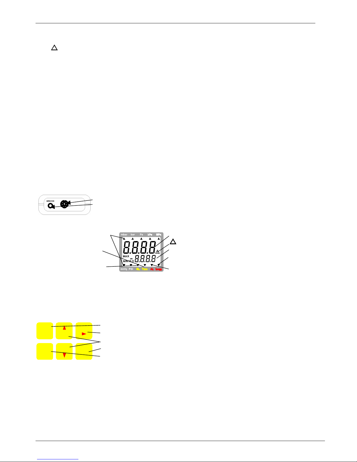
main display: shows measuring value.
!
: indicates weak battery or other warnings
secondary display: min-, max- or hold value
Logg: appears, if logger function is chosen,
flashes when logger is running
AL: (not at all devices) flashes, if alarm exists
Units: an arrow points to
the chosen measuring unit
Tara: appears if tarafunction is activated.
SL: appears if sea-levelcorrection is activated
1.2 Operation And Maintenance Advice
• Battery Operation
If and ´bAt´ are shown in the secondary display the battery has been used up and needs to be
replaced. The device will, however, operate correctly for a certain amount of time. If ´bAt´ is shown in the
upper display the voltage is too low to operate the device; the battery has been completely used up.
The battery has to be taken out, when storing device above 50°C.
Please note: We recommend to take out battery if device is not used for a longer period of time!
• Mains Operation With Power Supply
Warning: When using a power supply please note that operating voltage has to be 10.5 to 12 V DC.
Do not apply overvoltage!! Cheap 12V-power supplies often have excessive no-load voltage.
We, therefore, recommend using regulated voltage power supplies. Trouble-free operation is guaranteed
by our power supply GNG10/3000.
Prior to connecting the power supply to the mains make sure that the operating voltage stated at the
power supply is identical to the mains voltage.
! Connecting/Changing Sensors
Do not use insuitable sensors. Connecting other devices/sensors as specificated may cause a damage to
the instrument and device/sensor! Switch off device before changing the sensor.
Connect sensor before switching on the device, otherwise the sensor may not be detected correctly.
When connecting the sensor the connector may not lock correctly. In such case take the plug not at the
casing but at the buckling protection at the end of the plug. If plug is entered correctly, it will slide in
smoothly. To disconnect sensor do not pull at the cable but at the plug (to open locking mechanism).
1.3 Connections
Connection for pressure sensors of the GMSD-family (p.r.t. chapter 10)
Interface: Connection for el. isolated interface adapter (p.r.t. chapter 5)
The mains adapter socket is located at the left side of the device.
1.4 Display
1.5 Basic Operation
When switching on the device and the logger function is not off the time of the integrated clock will shortly
be displayed. If a zero point adjustment was carried out the display shows shortly „nuLL Corr“.
After changing the battery the clock-setting menu is activated automatically (‚CLOC‘). Check the clock and
adjust, if necessary (p.r.t. chapter 2).
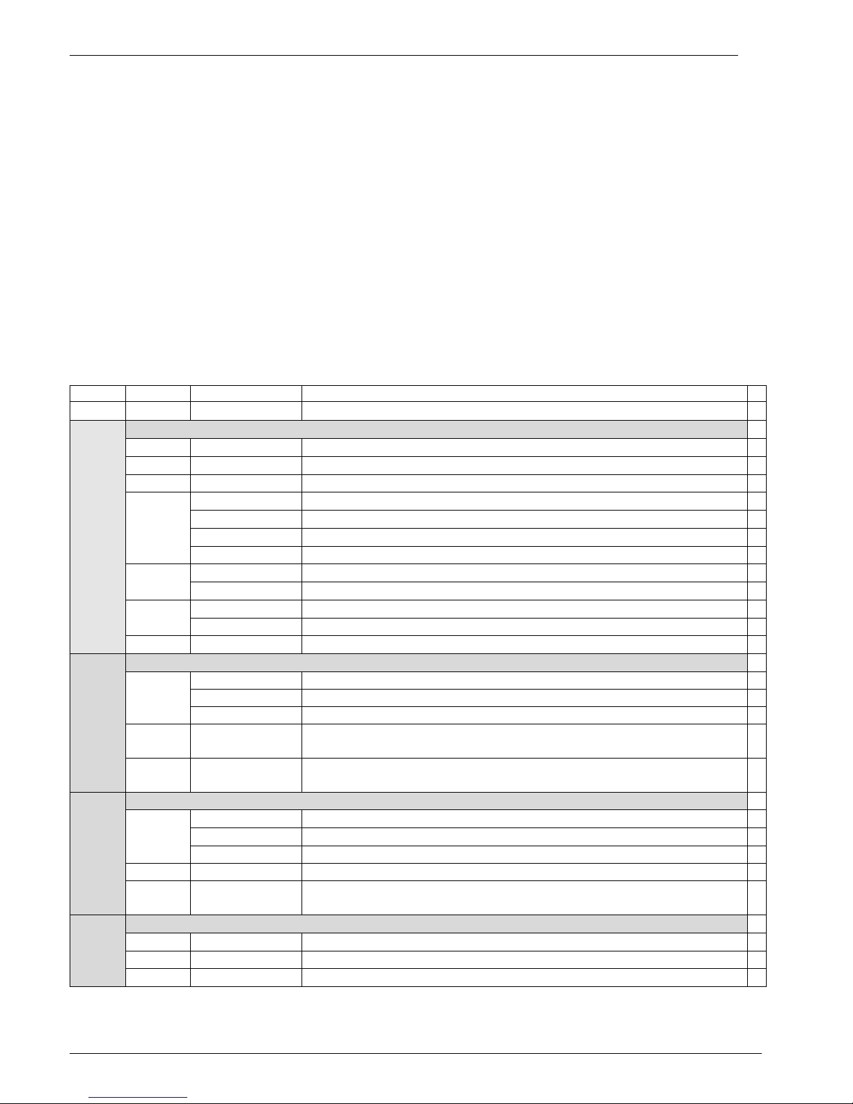
On-/Off-Switch
Tara: Calling of tara function, zero point adjustment
min/max: Showing the min- resp. max-memory in sec. display
Store/Quit: Calling of hold function resp. calling of logger functions (p.r.t. chapter 4)
Set/Menu: Calling of configuration
Max Memory: Pressing ´max´ (key 2) shows the maximum of the measured values. Pressing it again
hides it. To clear the max memory press key ´max´ for >2 seconds.
Min Memory: Pressing ´min´ (key 5) shows the minimum of the measured values. Pressing it again
hides it. To clear the min memory press key ´min´ for >2 seconds.
Hold Function: By pressing ´Store/Quit´ (key 6) the last measuring value will be held in the secondary
display. Pressing it again hides it. (only when logger = ‚off‘).
Tare Function: By pressing ´Tara´ (key 3) the display will be set to 0. All measurings from then on will be
displayed relatively to the set tare value. When tara function is activated, the arrow "Tara"
appears in the display. To deactivate tare function press ´Tara´ for >2 seconds.
Please Note: Activating/deactivating tara clears the max- & min-memories.
123
456
ON
OFF max
Tar a
Storemin
Set
Menu Quit
!
H31.0.31.6C-06 User’s Manual GMH3150 page 4
_______________________________________________________________________________________________________________________
Zero-Point Adjustment: (for rel. pressure sensors only) If there is no pressure applied to the pressure ports
the device will display 0. If there is a permanent deviation (and device is operated under
steady conditions), a permanent zero point adjustment can be carried out.
To carry out the adjustment press button 3 for approx. 5 seconds.
(Please note: A zero-point adjustment can only be carried out if the difference between the
value on display and the value calibrated on site is less than 2%! E.g. for the measuring
range of –1.00 ..+25.00mbar, =>zero-point adjustment up to 0.50mbar possible)
To recall the manufacturer`s calibration press button 3 for approx. 7 seconds.
Note: If a zero-point adjustment was carried out, this will be signalled by the short
displaying of „NuLL Corr“ when switching on the device.
2 Configuration
To change device settings, press Menu (key 4) for 2 seconds. This will call the configuration menu (main
display: „SEt“).
Pressing key Menu changes between the menues, pressing 4(key 3) jumps to the referring parameters,
which can be selected with key 4(key 3).
The parameters can be changed with 5 (key 2) or 6 (key 5).
Pressing Menu again jumps back to the main configuration menu and saves the settings.
Quit (key 6) finishes the configuration and returns to standard measuring operation.
Menu Param. Values Meaning
‚Menu‘
44445
or
6
Set Configuration: Generic Configurations
Unit
mbar,bar..
Unit: Unit of display *
SL
oFF/on
Sea level correction: on or off *
Alti
-2000..9999
Altitude: Input of altitude above sea level [m] (only if SL on) *
Rate: Measuring rate (p.r.t. chapter 2.1) *
Slo
Slow measuring rate (4Hz filtered, low power consumption) *
FASt
Fast measuring rate, filtered (>100Hz) *
rAtE
P.dEt
Peak detection: fast measuring rate, unfiltered (>100Hz) *
1-120
Averaging period in seconds, used by the averaging function
t.AVG
oFF
Averaging function deactivated
1-120
Auto Power Off time in minutes
P.oFF
oFF
Auto Power Off deactivated
SEt
ConF
Adr.
01,11..91
Base address of interface
Set Alarm: Settings Of Alarm Function
On
Alarm on, with horn-sound
no.So
Alarm on, without horn-sound
AL.
oFF
no alarm function
AL.Lo
Sensor-Min
... AL.Hi
Min alarm rail (not when AL. oFF, Sensor-Min is the lower display
range of connected sensor)
SEt
AL.
AL.Hi
AL.Lo ...
Sensor-Max
Max alarm rail (not when AL. oFF, Sensor-Max is the upper display
range of connected sensor)
Set Logger: Configuration Of Logger Function *
CYCL
Cyclic: logger function ‚cyclic logger‘ *
Stor
Store: logger function ‚individual value logger‘ *
Func
oFF
no logger function *
CYCL
1..3600
Cycle time of cyclic logger [seconds] *
SEt
LoGG
Lo.Po
on/oFF
Low-power logger with very low power consumption
(only for cyclic logger and slow measuring rate)
*
Set Clock: Setting Of Real Time Clock
CLOC
HH:MM
Clock: Setting of time hours:minutes
dAtE
TT.MM
Date: day.month
SEt
CLOC
YEAr
YYYY
Year
Note: If the logger memory contains data already, the menues/parameters marked with (*) can
not be invoked! If these should be altered the logger memory has to be cleared before!
(key 6, p.r.t. chapter 4)
 Loading...