

GREISINGER GLMU 400 MP-UNI, GLMU 400 MP, GLMU 200 MP Operating Manual

Operating Manual
Conductivity-Transmitter
without measuring cell
GLMU 400 MP -UNI
Keep for later use.
www.ghm-group.de
Companies / Brands of the GHM
Englisch

T46.0.21.6C-02 Operating Manual GLMU 400 MP_UNI (without measuring cell) page 2 of 10
GHM GROUP – Greisinger | GHM Messtechnik GmbH
Hans-Sachs-Str. 26 | 93128 Regenstauf | GERMANY
Phone +49 9402 9383-0 | Fax +49 9402 9383-33
www.greisinger.de | info@greisinger.de
Inhalt
1 General Advice ______________________________________________________________________ 3
2 Intended use ________________________________________________________________________ 3
2.1 Safety signs and symbols __________________________________________________________________ 3
2.2 Safety Instructions _______________________________________________________________________ 3
3 Installation _________________________________________________________________________ 4
3.1 Dimensions _____________________________________________________________________________ 4
3.2 Assignment of elbow-type plug _____________________________________________________________ 4
3.3 Terminal assignment of meas. cell socket _____________________________________________________ 4
3.4 Usage of Unit-Labels ______________________________________________________________________ 5
4 Operation __________________________________________________________________________ 5
4.1 General information about the conductivity measuring __________________________________________ 5
4.1.1 The measuring cell ________________________________________________________________________________ 5
4.1.2 Measuring hints __________________________________________________________________________________ 5
4.1.3 Temperature compensation ________________________________________________________________________ 5
4.1.4 Salinity measuring ________________________________________________________________________________ 6
4.1.5 TDS measuring ___________________________________________________________________________________ 6
5 Display functions ____________________________________________________________________ 6
5.1 Currently measured values _________________________________________________________________ 6
5.1.1 Min/Max Value Memory ___________________________________________________________________________ 6
6 Error and system messages ____________________________________________________________ 6
7 Configuration _______________________________________________________________________ 8
7.1 'C.rnG': Setting of Cell Constant: Cell constant range ____________________________________________ 8
7.2 'CELL': Setting of the cell-constant of the connected measuring cell ________________________________ 8
7.3 'Func': Setting of the measuring function _____________________________________________________ 8
7.4 'rAnG': Setting of the measuring range (not at “Func SAL”) _______________________________________ 8
7.5 't.Cor': Setting of temperature compensation method (not at “Func SAL”) __________________________ 9
7.6 't.Lin': Setting of temperature coefficient (only for t.Cor = Lin) ____________________________________ 9
7.7 't.rEF': Setting of reference temperature (only for t.Cor = nLF or Lin) _______________________________ 9
7.8 'C.tdS': Setting of TDS-factor _______________________________________________________________ 9
7.9 't.InP' t-Input: Temperatureinput ____________________________________________________________ 9
7.10 'dA.Lo': Display at zero output (output scaling) ________________________________________________ 9
7.11 'dA.Hi': Display at maximum output (output scaling) ____________________________________________ 9
7.12 'Unit' with Temp-arrow: Temperature unit ____________________________________________________ 9
7.13 'OFFS' with Temp-arrow: Offset of temperature measuring ______________________________________ 9
7.14 'SCAL' with Temp-arrow: Scale correction of temperature measuring ______________________________ 9
8 Reshipment and Disposal _____________________________________________________________ 10
8.1 Reshipment ____________________________________________________________________________ 10
8.2 Disposal instructions _____________________________________________________________________ 10
T46.0.21.6C-02 Operating Manual GLMU 400 MP_UNI (without measuring cell) page 3 of 10
GHM GROUP – Greisinger | GHM Messtechnik GmbH
Hans-Sachs-Str. 26 | 93128 Regenstauf | GERMANY
Phone +49 9402 9383-0 | Fax +49 9402 9383-33
www.greisinger.de | info@greisinger.de
9 Calibration Services _________________________________________________________________ 10
10 Specification _____________________________________________________________________ 10
11 Variants/ Measuring Cells and Accessories _____________________________________________ 11
1 General Advice
Read this document carefully and get used to the operation of the device before you use it. Keep this document within easy reach near the device for consulting in case of doubt.
Mounting, start-up, operating, maintenance and removing from operation must be done by qualified, specially
trained staff that have carefully read and understood this manual before starting any work.
The manufacturer will assume no liability or warranty in case of usage for other purpose than the intended
one, ignoring this manual, operating by unqualified staff as well as unauthorized modifications to the device.
The manufacturer is not liable for any costs or damages incurred at the user or third parties because of the
usage or application of this device, in particular in case of improper use of the device, misuse or malfunction
of the connection or of the device.
The manufacturer is not liable for misprints.
2 Intended use
The GLMU 400 MP-UNI is a universal transmitter for measuring conductivity or other units based on conductivity measuring in liquids.
The measurement is performed by means of alternating current flow between the poles of the measuring
cell, being in direct contact with the liquid.
The measurement is displayed via analogue standard signal output and a liquid crystal display.
The 4-20 mA model is supplied by the current loop, the 0-1 or 0-10 V model requires separate power supply.
The configuration of the various parameters has to be checked prior to use.
The measuring cell is included in the scope of supply and prior to measuring a suitable cell has to connected
and configured.
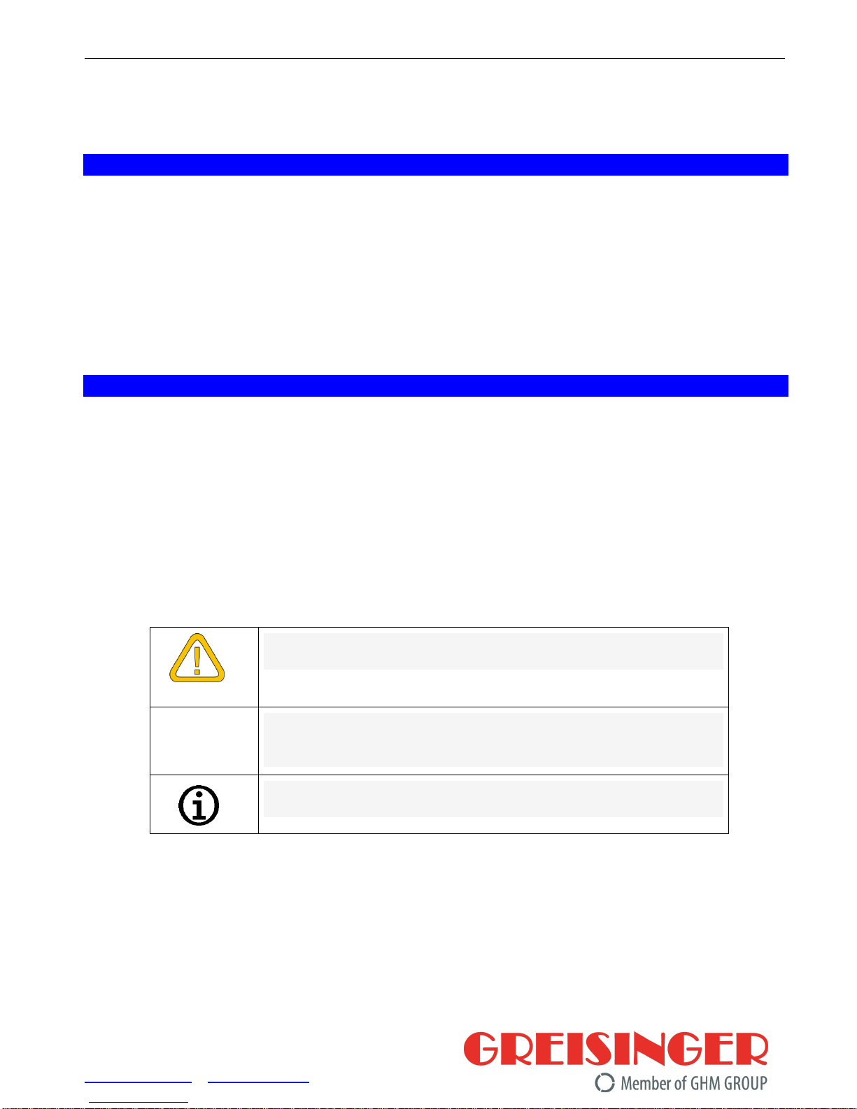
2.1 Safety signs and symbols
Warning notices are marked in this manual as shown below:
DANGER
Warning! Symbol warns of impending danger, death, serious
bodily injury or serious property damage if ignored.
Attention! Symbol warns of potential hazards or hazardous situations that can cause damage on the equipment or the environment if ignored.
Note! Symbol indicates incidents that have an indirect impact on
the operation or can trigger an unforeseen reaction if ignored.
2.2 Safety Instructions
This device has been designed and tested in accordance to the safety regulations for electronic devices.
However, its trouble-free operation and reliability cannot be guaranteed unless the standard safety measures
and special safety advises given in this manual will be adhered to when using it.
1. Trouble-free operation and reliability of the device can only be guaranteed if it is not subjected to any
other climatic conditions than those stated under “Specification”.
Transporting the device from a cold to a warm environment condensation may result in a failure of the
function. In such a case make sure the device temperature has adjusted to the ambient temperature before trying a new start-up.

T46.0.21.6C-02 Operating Manual GLMU 400 MP_UNI (without measuring cell) page 4 of 10
GHM GROUP – Greisinger | GHM Messtechnik GmbH
Hans-Sachs-Str. 26 | 93128 Regenstauf | GERMANY
Phone +49 9402 9383-0 | Fax +49 9402 9383-33
www.greisinger.de | info@greisinger.de
2. General instructions and safety regulations for electric, light and heavy current plants, including domestic
safety regulations (e.g. VDE), have to be observed.
3. Whenever there may be a risk whatsoever involved in running it, the device has to be
switched off immediately and to be marked accordingly to avoid re-starting. Operator safety
may be a risk if:
- there is visible damage to the device
- the device is not working as specified
- the device has been stored under unsuitable conditions for a longer time
In case of doubt, please return device to manufacturer for repair or maintenance.
4. Do not use this product as safety or emergency stop device or in any other application where
failure of the product could result in personal injury or material damage.
Failure to comply with these instructions could result in death or serious injury and material
damage.
3 Installation
3.1 Dimensions
General elbow-type plug installation instructions
To mount the connection cable (2-, or 3-wire depending on type of
device) the elbow-type plug screw has to be loosened and the coupling insert has to be removed by means of a screw driver at the
position indicated (arrow).
Pull out connection cable through glanding and connect to the
loose coupling insert as described in the wiring diagram.
Replace loose coupling insert onto the pins at the transmitter housing and turn cover cap with cable outlet in the direction desired untill
it snaps on (4 different starting positions at 90° intervals).
Re-tighten the screw at the angle plug.
3.2 Assignment of elbow-type plug
4-20 mA (2-wire-connection).
voltage (3-wire connection).
1 = supply +
2 = GND / signal
1 = signal +
3 = supply +Uv
(4) = supply -Uv
The type current or voltage output is set by works and cannot be changed
3.3 Terminal assignment of meas. cell socket
contact no.
2 pole-cell
4 pole-cell
1
temperature +
temperature +
2
temperature GND
temperature GND
3
supply 1 (electrode 1)
supply 1 (outer electrode 1)
4
signal 1 (electrode 1)
signal 1 (outer electrode 1)
5
signal 2 (electrode 2)
signal 2 (inner electrode 2)
6
supply 2 (electrode 2)
supply 2 (inner electrode 2)
7
not used
not used
DANGER
DANGER
 Loading...