

T14.0.0Y.6C-03
Conductivity-Transmitter
with 4 pole measuring cell (graphite)
as of version 1.2 Operating Manual GLMU 200 MP
Contents
1 Intended use 2
2 General Advice 2
3 Safety Requirements 2
4 Disposal instructions 2
5 Calibration Service 2
6 Installation 3
7 Operation 4
8 Display functions 5
9 Error and system messages 5
10 Configuration 6
11 Specification 8
GREISINGER electronic GmbH
D - 93128 Regenstauf, Hans-Sachs-Straße 26
Tel.: +49 9402 9383-0, Fax: +49 9402 9383-33, eMail: info@greisinger.de
T14.0.0Y.6C-03 Operating Manual GLMU 200 MP page 2 of 8
1 Intended use
The GLMU 200 MP is a transmitter for measuring conductivity or other units based on conductivity measuring in liquids.
The measurement is performed by means of alternating current flow between the poles of the measurement
cell, being in direct contact with the liquid.
The measurement is displayed via analogue standard signal output and a liquid crystal display.
The 4-20 mA model is supplied only by the current loop, the 0-.. V model required a separate power supply.
The configuration of the various parameters has to be checked prior to use.
2 General Advice
Read through this document attentively and make yourself familiar to the operation of the device before you
use it. Keep this document in a ready-to-hand way in order to be able to look up in the case of doubt.
3 Safety Requirements
This device has been designed and tested in accordance with the safety regulations for electronic devices.
However, its trouble-free operation and reliability cannot be guaranteed unless the standard safety measures
and special safety advises given in this manual will be adhered to when using the device.
1. Trouble-free operation and reliability of the device can only be guaranteed if the device is not subjected to
any other climatic conditions than those stated under "Specification".
If the device is transported from a cold to a warm environment condensation may cause in a failure of the
function. In such a case make sure the device temperature has adjusted to the ambient temperature before trying a new start-up.
2. General instructions and safety regulations for electric, light and heavy current plants, including domestic
safety regulations (e.g. VDE), have to be observed.
3. If device is to be connected to other devices (e.g. via PC) the circuitry has to be designed most carefully.
Internal connection in third party devices (e.g. connection GND and earth) may result in not-permissible
voltages impairing or destroying the device or another device connected.
4. If there is a risk whatsoever involved in running it, the device has to be switched off immediately and to be
marked accordingly to avoid re-starting.
Operator safety may be a risk if:
- there is visible damage to the device
- the device is not working as specified
- the device has been stored under unsuitable conditions for a longer time
In case of doubt, please return device to manufacturer for repair or maintenance.
5. Warning:
Do not use these products as safety or emergency stop devices, or in any other application where failure of
the product could result in personal injury or material damage. Failure to comply with these instructions
could result in death or serious injury and material damage.
4 Disposal instructions
This device must not be disposed as ‘residual waste’.
To dispose this device, please send it directly to us (adequately stamped).
We will dispose it appropriately and environmentally friendly.
5 Calibration Services
Factory calibration certificate - DKD certificate - official certifications:
If the measuring instrument is supposed to receive a factory calibration certificate, it has to be sent to the
manufacturer.
Just the manufacturer can check the factory settings and correct them if necessary.
T14.0.0Y.6C-03 Operating Manual GLMU 200 MP page 3 of 8
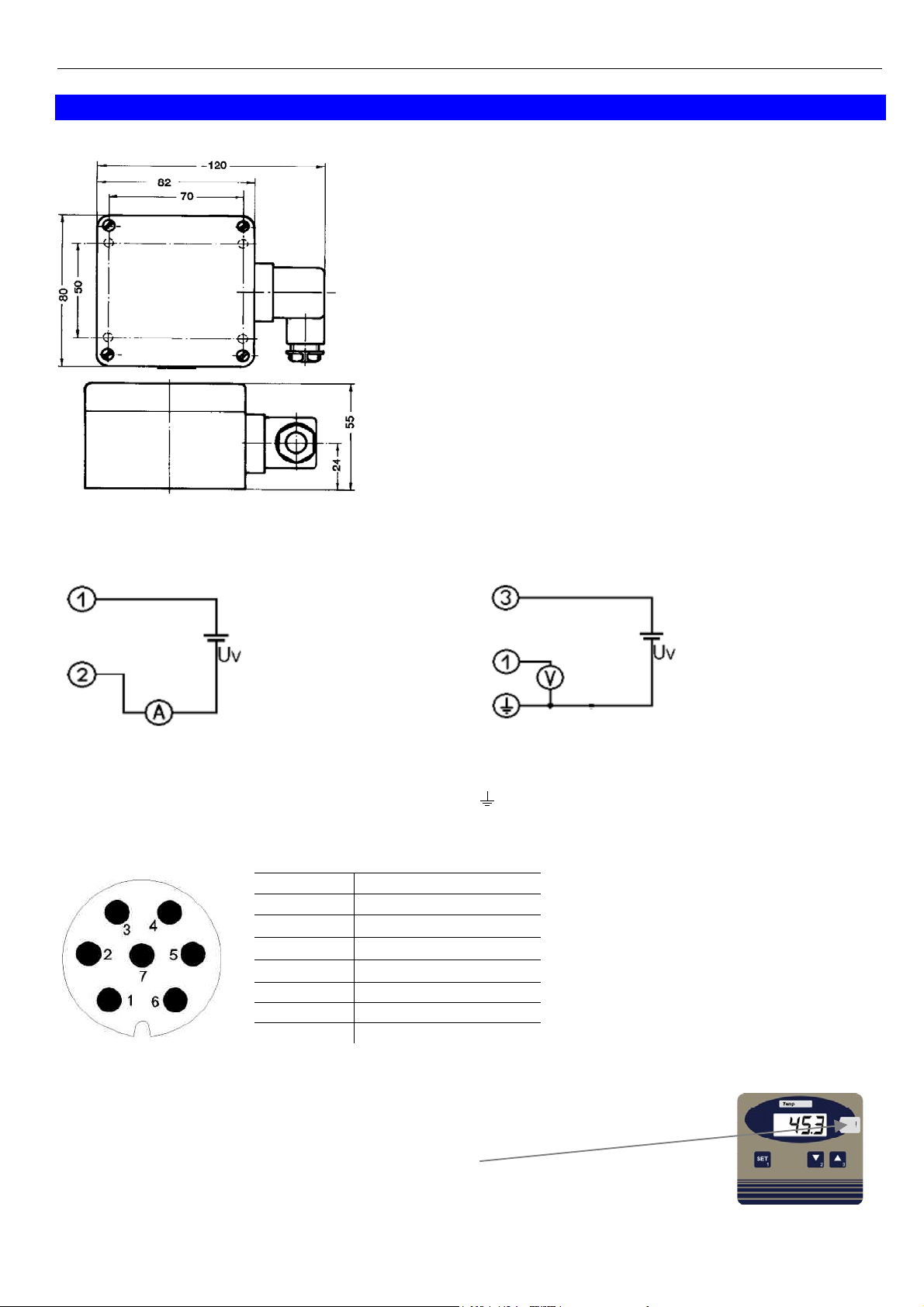
6 Installation
Dimensions
General elbow-type plug installation instructions
To mount the connection cable (2-, or 3-wire depending on type of
device) the elbow-type plug screw has to be loosened and the coupling insert has to be removed by means of a screw driver at the
position indicated (arrow).
Pull out connection cable through glanding and connect to the
loose coupling insert as described in the wiring diagram.
Replace loose coupling insert onto the pins at the transmitter housing and turn cover cap with cable outlet in the direction desired untill
it snaps on (4 different starting positions at 90° intervals).
Re-tighten the screw at the angle plug.
6.1 Assignment of elbow-type plug
4-20 mA (2-wire-connection). voltage (3-wire connection).
1 = supply +
2 = GND / signal
1 = signal +
3 = supply voltage +Uv
(4) = supply voltage -Uv
The type current or voltage output is set by works and cannot be changed
6.2 Terminal assignment of meas. cell socket
contact no.
1 temperature +
2 temperature GND
3 measuring cell 1
4 measuring cell 1
5 measuring cell 2
6 measuring cell 2
7 not used
2 pole-cell (K ~ 1)
6.3 Usage of Unit-Labels
As the transmitter is a multiple purpose device, many different display units are possible, e.g. µS/cm, kOhm·cm.
Therefore unit-labels (within scope of supply) can be shoved between the case cover
and the front foil behind the transparent unit-window.
To replace a label, unscrew the cover, pull out the old label (if present) and shove in the
new one.
The unit depends on the settings of the Cell-constant, the function and the measuring range!
Please refer to table in chapter “Configuration of the device”

T14.0.0Y.6C-03 Operating Manual GLMU 200 MP page 4 of 8
7 Operation
7.1 General information about the conductivity measuring
7.1.1 The measuring cell
During the measurement, the conductivity measuring cell must be dipped at least in so far, that at least
30 mm beginning from the top of the measuring cell, is located in the medium.
The maximum immersion depth for continuous operation should not exceed 110 mm.
The measuring cell can either be stored dry or in water. After dry storage wetting time will be prolonged
slightly. If changing over from one liquid to another with conductivity varying widely make sure to properly
rinse the measuring cell with deionised water.
Attention: Measuring cell must never come into contact with water-repellent materials such as oil
or silicone.
If conductivity measured is much higher or lower than expected this may be due to the measuring being
soiled with non-conducting or conducting extraneous materials. The measuring cell has to be cleaned e.g.
with a watery soap solution.
When measuring media at low conductivity the measuring cell has to be stirred sufficiently.
7.1.2 Measuring hints
Conductivity measuring is comparably easy to perform, the precision of the instrument is very constant if it is
used as intended. Depending on the necessary accuracy the instruments can be used up to several years
without re-calibration of the cell constant.
If the accuracy should be controlled or improved, this is done by means of suitable reference solutions and
the adjusting of the cell factor.
Attention! Wrong handling of reference solution can make them useless very fast.
Measuring procedure:
Especially when measuring low conductivity: Before immersion to the measuring solution, rinse the measuring cell with deionised water.
The measuring is speeded up considerably, if the measuring cell is immersed and pulled out the solution
several times. Especially when measuring low conductivity the measuring cell needs sufficient flow during the
measuring, e.g. via stirring the solution.
Sufficient time has to be waited for, until the measuring cell has adjusted to the measuring solution temperature.
7.1.3 Temperature compensation
The conductivity of aqueous solution is temperature dependent. The dependency itself is strongly dependent
on the kind of solution. For the most applications e.g. in fish farming etc., the non linear temperature compensation of natural waters is precise (“nLF” according to EN 27888). The most common reference temperature is 25 °C.
7.1.4 .Salinity measuring
The salinity (salt content) of seawater can be determined in the measuring mode „SAL“ (basis: International
Oceanographic Tables; IOT)
The salinity of standard-seawater is 35 ‰ ( 35 g salt per 1 kg seawater).
The values are displayed in ‰ (g/kg).
7.1.5 TDS measuring
At the TDS measuring the dry residues or total d
issolved solids value is calculated by means of the conductivity and a calculation factor (C.tdS). This factor has to be evaluated for the referring type of solution.
The values are displayed in mg/l.

T14.0.0Y.6C-03 Operating Manual GLMU 200 MP page 5 of 8
A
8 Display functions
8.1 Currently measured values
During normal operation the conductivity display value is displayed.
By short press of key ‘SET’ (1) the temperature in [°C] will displayed for 10 seconds.
rrow to Temp indicates
temperature display
display of conductivity value display temperature
8.1.1 Min/Max Value Memory
watch Min values (Lo): press ‘down‘(2) shortly once display changes between ‘Lo‘ and Min values
watch Max values (Hi): press ‘up‘(3) shortly once display changes between ‘Hi‘ and Max values
restore current values: press ‘down‘(2) or ’up’(3) once again current values are displayed
clear Min-values: press ‘down’(2) for 2 seconds Min values are cleared. The display shows shortly ‘CLr‘.
clear Max-values: press ‘up’(3) for 2 seconds Max values are cleared. The display shows shortly ‘CLr‘.
After 10 seconds the currently measured values will be displayed again.
9 Error and system messages
Display Description Possible fault cause Remedy
Temperature above 140°C not allowed.
Choose right measuring range for conductivity
Temperature below -5°C not allowed.
Choose right measuring range for conductivity
Disconnect from supply and reconnect.
If error remains: return to manufacturer
Check temperature
Err.1
Err.2
Err.7
Err.9
Er.11
8.8.8.8
measuring range exceeded
Measuring value below
measuring range
System fault Error in device
Sensor error Sensor or cable defective Check sensor, cable and connections
Calculation not possible
Segment test
Wrong signal
Wrong signal
Calculation variable
missing or invalid
The transducer performs a display test for 2 seconds after power up.
After that it will change to the display of the measuring.

T14.0.0Y.6C-03 Operating Manual GLMU 200 MP page 6 of 8
10 Configuration
In the configuration the devices parameters can be changed.
The jumper has to be set, p.r.t. figure right hand side. To set or
remove jumper, the housing cover has to be removed. Ex works
the jumper is set.
To change parameters press “SET” (key 1) two seconds, then the
parameter selection is started with the first parameter (display
shows “CELL”).
By pressing “SET” the desired parameter is selected, the editing of
the parameter values happens via keys 5 (key 3) or 6 (key 2).
Pressing “SET” again (after editing the parameter values) returns
to the parameter selection
Pressing “SET” again after the last parameter finishes the configuration, stores the changes and restarts the device.
10.1 'CELL': Setting of the cell-constant of the connected measuring cell
Possible inputs: 0.300...1.200. Unit is 1/cm.
The value was evaluated and stored ex works for the connected measuring cell (in between 0.80...1.20).
If the jumper is removed from
the shown contacts, the configuration is inaccessible, values are protected.
10.2 'Func': Setting of the measuring function
Possible inputs: cond conductivity
reSi: resistivity
tdS: TDS (total dissolved solids
SAL: Salinity = salt content of sea water
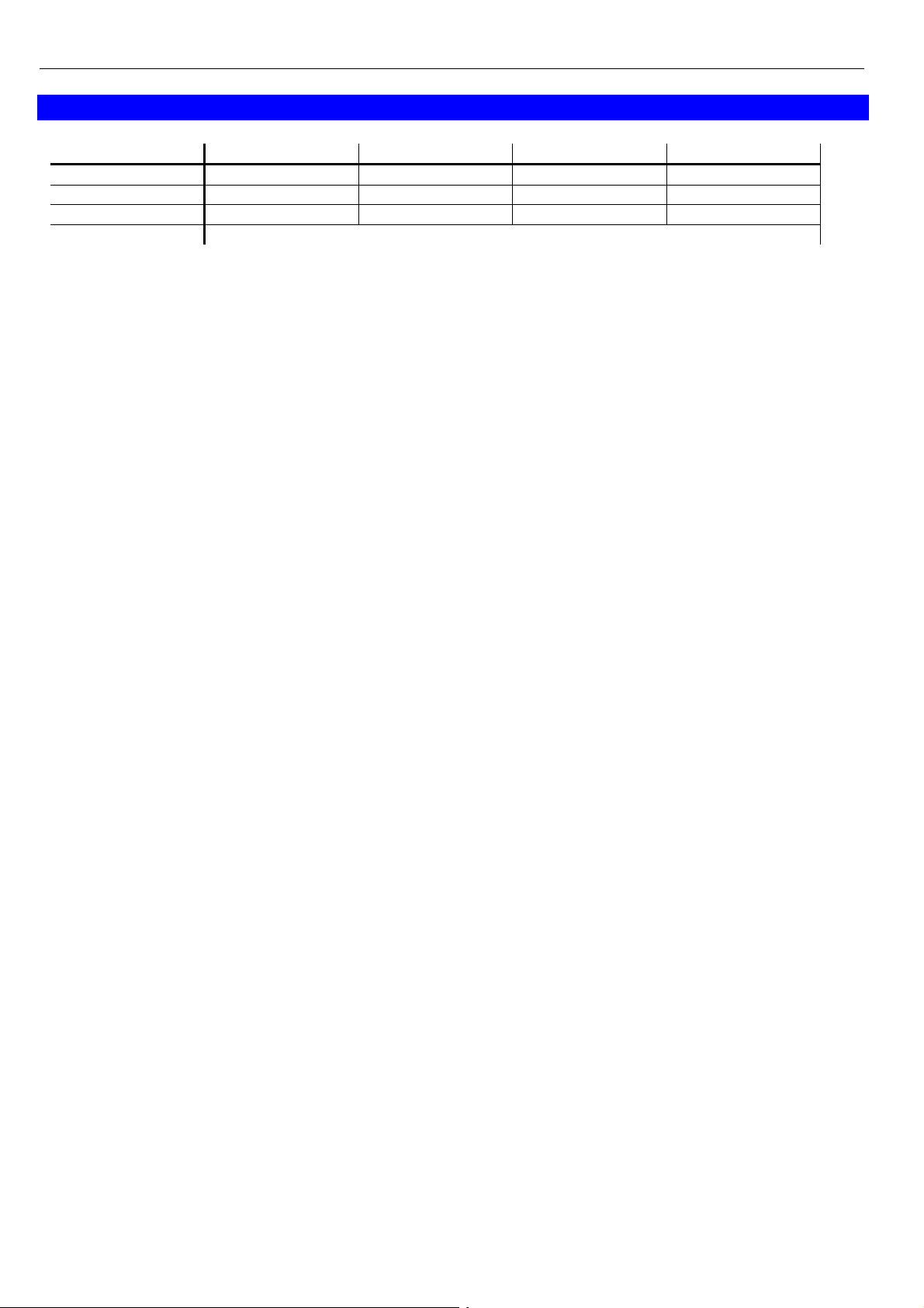
10.3 'rAnG': Setting of the measuring range (not at “Func SAL”)
Choice the desired measuring range (range is depending on the function set above).
Possible inputs:
Range (rAnG) = 0 Range (rAnG) = 1 Range (rAnG) = 2 Range (rAnG) = 3
Conductivity (cond) 0,0 - 200,0 mS/cm 0,00 - 20,00 mS/cm 0 - 2000 µS/cm 0,0 - 200,0 µS/cm
Resistivity (rESi) 5,0 - 100,0 Ohm·cm 50 - 1000 Ohm·cm 0,50 - 10,00 kOhm·cm 5,0 - 100,0 kOhm·cm
TDS (tdS) -- -- 0 - 2000 mg/l 0,0 - 200,0 mg/l
Salinity (SAL) 0,0 - 70,0
10.4 't.Cor': Setting of temperature compensation method (not at “Func SAL”)
Possible inputs: off: no temperature compensation
nLF:non linear compensation for natural water according to EN 27888 (DIN 38404).
For measurings of ground and surface water, drinking water or pure water.
Attention: restricted temperature range: -5..105 °C
Lin: linear temp. compensation (for other aqueous solutions, factor has to be entered)
10.5 't.Lin': Setting of temperature coefficient (only for t.Cor = Lin)
Possible input: 0.300 .. 3.000 [%]
If it is only measured in a narrow conductivity range, the temperature compensation factor of this range can
be determined.
10.6 't.rEF': Setting of reference temperature (only for t.Cor = nLF or Lin)
Possible input: 20 °C or 25 °C
10.7 'C.tdS': Setting of TDS-factor
Calculation factor for TDS (Total Dissolved Solids)-measurements, possible input: 0.40 .. 1.00.
The calculation factor depends on the composition of the medium and has to be determined
for each type of water.

T14.0.0Y.6C-03 Operating Manual GLMU 200 MP page 7 of 8
10.8 'dA.Lo': Display at zero output (output scaling)
Enter the display value at which the output should have 4 mA (or 0 V).
The value range is depending on the selected measuring function (Func) and range (rAnG).
10.9 'dA.Hi': Display at maximum output (output scaling)
Enter the value at which the output should have 20 mA (or 1 / 10 V).
The value range is depending on the selected measuring function (Func) and range (rAnG).
10.10 'Unit' with Temp-arrow: Temperature unit
Temperature unit: All referring settings and displays are done in this unit.
Choice between °C and °F (ex works: °C)
10.11 'OFFS' with Temp-arrow: Offset of temperature measuring
The offset of the measuring will be shifted by this value, the input is in °C. Calculation: see below.
Max. input range: -5.0...5.0 °C or 'oFF' (= 0.0°) (factory setting = off)
10.12 'SCAL' with Temp-arrow: Scale correction of temperature measuring
The scale of the measuring is changed by this value. Calculation: see below.
Max. input range: -5.00...5.00 or 'oFF' (= 0.00) (factory setting = off)
The adjusting of the temperature by means of offset and scale is intended to be used to compensate deviations of the measuring. It is recommended to keep the scale correction deactivated (“oFF”). The display
value is given by following formula:
Temperature display = measured value - offset
With a scale correction (just for calibration laboratories, etc) the formula changes:
Temperature display = (meas. value - offset) * ( 1 + scale correction/100)
After pressing key 1 again, the instrument will restart (display 8888).
T14.0.0Y.6C-03 Operating Manual GLMU 200 MP page 8 of 8
11 Specification
Measuring range 1 (one of the following can be configured):
Range (rAnG) = 0 Range (rAnG) = 1 Range (rAnG) = 2 Range (rAnG) = 3
Conductivity (cond) 0,0 - 200,0 mS/cm 0,00 - 20,00 mS/cm 0 - 2000 µS/cm 0,0 - 200,0 µS/cm
Resistivity (rESi) 5,0 - 100,0 Ohm·cm 50 - 1000 Ohm·cm 0,50 - 10,00 kOhm·cm 5,0 - 100,0 kOhm·cm
TDS (tdS) -- -- 0 - 2000 mg/l 0,0 - 200,0 mg/l
Salinity (SAL) 0,0 - 70,0
Meas. range 2 Temperature (only display) -5.0...140.0 °C (resolution 0.1°C or 0.1°F, NTC10k)
Attention: Consider application range of measuring cell: 0..80°C
Accuracy: (at nominal temperature = 25°C)
Measuring: conductivity: ±0,5% of measured value ±0,3 FS
temperature: ±0.1°C of measured value ±1 Digit
Add. output signal: ±0.2 % FS
Measuring cell: 2 pole measuring cell with graphite electrodes, integrated NTC temperature sensor,
Cell constant K: 0.80..1.20, determined and adjusted ex works
7 pole connector
Temp. compensation: non linear function, linear function (coefficient configurable) or none
Min-/Max-Value Memory: Min and max measured values are stored
Output signal: refer to type plate, freely scaleable
Scaling: By entering display values for 4mA (or 0V) and 20mA (or 1V/10V) output
Connection: 4 - 20 mA type: 2-wire – output signal electrically isolated
options AV01 (0-1 V), AV10 (0-10 V): 3-wire – output signal electrically isolated
Auxiliary energy (supply voltage): Uv = 12 - 30 V DC (4-20 mA)
Uv = 12 - 30 V DC, max. 10mA (0-1V)
Uv = 18 - 30 V DC, max. 10 mA (0-10 V)
or refer to type plate
Rev. voltage protection: 50 V permanent
Perm. impedance (at 4-20mA): RA(Ohm) < ( (Uv – 12 V) / 0.02 A )
Example: for Uv = 18V: RA < (18 V – 12 V) / 0.02 A => RA < 300 Ohm
Permissible load (at 0-...V): RL(Ohm) > 3000 Ohm
Adjusting: via keys. Conductivity by editing cell constant K (CELL)
Temperature by offset and scale.
Display: approx. 10 mm high, 4-digit LCD-display
Ambient conditions for electronics:
Nominal temperature: 25°C
Operating condition: -25 to 50°C, 0 to 95 %RH (non-condensing)
Storage temperature: -25 to 70°C
Ambient of meas. Cell: -5 to 80°C (short time up to 100°C)
Housing: ABS (IP65)
Dimensions: 82 x 80 x 55 mm (without elbow-type plug and sensor connector)
Mounting: With holes for wall mounting (in housing - accessible after cover has been removed).
Mounting distance: 50 x 70mm, max. shaft diameter of mounting screws is 4 mm.
Electrical connection: elbow-type plug conforming to DIN 43650 (IP65),
max. wire cross section: 1.5 mm², wire/cable diameter from 4.5 to 7 mm
EMC: In accordance with EN61326 +A1 +A2 (appendix A, class B), additional errors: < 1% FS.
When connecting long leads adequate measures against voltage surges have to be taken.
The electrode connections have to be protected sufficiently against ESD pulses, if the device is used in areas with risk of ESD.
 Loading...