

E33.0.31.6C-02 Manual for connection and operation of the GIR230 Pt1000 / DIF and GIR230 NTC /DIF Page 1 of 14
Manual for connection and operation of
GIR 230 Pt1000 / DIF
GIR 230 NTC / DIF
Version 1.3

E33.0.31.6C-02 Manual for connection and operation of the GIR230 Pt1000 / DIF and GIR230 NTC /DIF Page 2 of 14
Index
1. SAFETY REGULATIONS .......................................................................................................................................... 3
2. INTRODUCTION ........................................................................................................................................................4
3. ELECTRICAL CONNECTION.................................................................................................................................. 4
3.1. Terminal assignment................................................................................................................................................ 4
3.2. Connection data ....................................................................................................................................................... 4
3.3. Connecting an input signal.......................................................................................................................................5
3.3.1. Connecting of the temperature probes .............................................................................................................. 5
3.4. Connecting switching outputs.................................................................................................................................. 5
3.4.1. Connection of the relay outputs .................................................................................................................... 5
3.4.2 Connection of output 3 (NPN-output, switching to ground)............................................................................ 5
4. CONFIGURATION OF THE DEVICE ..................................................................................................................... 6
4.1. Selecting an input signal type .................................................................................................................................. 6
4.2. Selection of the output function............................................................................................................................... 7
5. SWITCHPOINTS AND ALARM-BOUNDARIES.................................................................................................... 8
5.1. 2- point-controller, 3- point-controller..................................................................................................................... 8
5.2. 2-point-controller with alarm function, 3-point-controller with alarm function ...................................................... 9
5.3. Minimum/maximum-alarm.................................................................................................................................... 10
6. MIN-/MAX-ALARM DISPLAY ............................................................................................................................... 10
7. DISPLAYING THE MEASURING VALUE OF INPUT 1 OR INPUT 2 ............................................................. 10
8. MIN-/MAX-VALUE STORAGE .............................................................................................................................. 10
9. OFFSET- AND SLOPE-ADJUSTMENT ................................................................................................................. 11
10. ERROR CODES ....................................................................................................................................................... 12
11. SPECIFICATION..................................................................................................................................................... 13
E33.0.31.6C-02 Manual for connection and operation of the GIR230 Pt1000 / DIF and GIR230 NTC /DIF Page 3 of 14
1. Safety regulations
This device was designed and tested considering the safety regulations for electronic measuring devices.
Faultless operation and reliability in operation of the measuring device can only be assured if the General
Safety Measures and the devices specific safety regulations mentioned in this users manual are considered.
1. Faultless operation and reliability in operation of the measuring device can only be assured if the device
is used within the climatic conditions specified in the chapter “Specification“
2. Always disconnect the device from its supply before opening it. Take care that nobody can touch any of
the devices contacts after installing the device.
3. Standard regulations for operation and safety for electrical, light and heavy current equipment have to be
observed, with particular attention paid to the national safety regulations (e.g. VDE 0100).
4. When connecting the device to other devices (e.g. the PC) the interconnection has to be designed most
thoroughly, as internal connections in third-party devices (e.g. connection of ground with protective earth)
may lead to undesired voltage potentials.
5. The device must be switched off and must be marked against re-starting, in case of obvious malfunctions
of the device which are e.g.:
- visible damage.
- the device is not working as prescribed.
- after storage of the device under inappropriate conditions for longer time.
In case of doubt, the device should be sent to the manufacturer for repairing or servicing.
ATTENTION: When running electric devices, parts of them will always be electrically
live. Unless the warnings are observed serious personal injuries or damage to property may result. Skilled personnel only should be allowed to work with this device. For
trouble-free and safe operation of the device please ensure professional transport,
storage, installation and connection as well as proper operation and maintenance.
SKILLED PERSONNEL
Are persons familiar with installation, connection, commissioning and operation of the product and have
professional qualification relating to their job.
For example:
• Training or instruction respectivley qualifications to switch on or off, isolate, ground and mark electric circuits and devices or systems.
• Training or instruction according to the state.
• First-aid training.
ATTENTION:
Do NOT use this product as safety or emergency stopping device, or in any other application where failure of the product could result in personal injury or material damage.
Failure to comply with these instructions could result in death or serious injury and
material damage.

E33.0.31.6C-02 Manual for connection and operation of the GIR230 Pt1000 / DIF and GIR230 NTC /DIF Page 4 of 14
2. Introduction
GIR230 Pt1000 / DIF and the GIR230 NTC / DIF is a microprocessor controlled displaying, monitoring and
controlling device.
The device is supporting two interface for the connection of:
- Pt1000 (2-wire-technology) at type GIR230 Pt1000 / DIF
- NTC (2-wire-technology) at type GIR230 NTC / DIF
The display and regulation will occur to the difference (sensor 1 – sensor 2)
of the both measuring inputs.
The device features three switching outputs (2 * Relays, 1 * NPN-Output), which can be configured as 2point-controller, 3-point-controller, 2-point-controller with min./max. alarm, 3-point-controller with min./max.
alarm, or just individual min./max. alarm.
The state of the relay outputs is displayed with two LED’s beneath the front 4-digit LED-display. The left LED
displays the state of the 1st relay, the right LED displays the state of the 2nd relay.
If there is an alarm condition the display alternates between value and AL.Lo or AL.Hi.
When leaving factory the GIR230 has been subjected to various inspection tests and is completely cali-
brated.
Before the GIR230 can be used, it has to be configured for the customer’s application.
Hint: In order to avoid undefined input states and unwanted or wrong switching processes, we sug-
gest to connect the device’s switching outputs after You have configured the device properly.
3. Electrical connection
Wiring and commissioning of the device must be carried out by skilled personnel only.
In case of wrong wiring the device may be destroyed. We can not assume any warranty in case of
wrong wiring of the device.
3.1. Terminal assignment
1
Relay-output 2 (230V
2
Relay-output 1 (230V
3
Supply voltage, 230V
4
Supply voltage, 230V
5
Output 3
6
GND
7
temperature sensor 2
8
temperature sensor 1
3.2. Connection data
AC)
AC)
AC
AC
between
terminals
typical limitations
min. max. min. max.
67851234
notes
Out 3
GND
Rel 2
Rel 1
230 V ~
230 V ~
Sensor 2
Sensor 1
AC
244 V
AC
0 V
AC
DC
253 V
5 A,
ohm resistive load
28 VDC,
I < 30mA
Supply voltage 3 and 4
Relay outputs 1 and 2
Output 3
(NPN, open collector)
1 and 3,
2 and 3
5 and 6 0 V
207 V
6 and 8,
Input temperature sensor
7 and 8,
0 Ω∞ Ω
6 and 7
These limits must not be exceeded (not even for a short time) !
AC
No active signal allowed
E33.0.31.6C-02 Manual for connection and operation of the GIR230 Pt1000 / DIF and GIR230 NTC /DIF Page 5 of 14
3.3. Connecting an input signal
Please take care not to exceed the limitations of the inputs when connecting the device as this may lead
to destruction of the device..
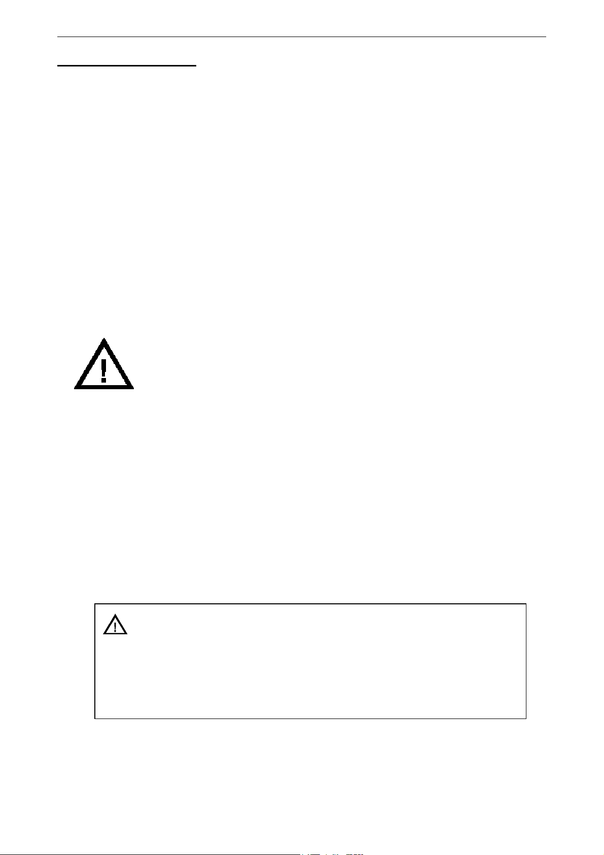
3.3.1. Connecting of the temperature probes
1
2
3
4
5
6
7
8
temperature probe (2-wire-technology) – sensor 1 temperature probe (2-wire-technology) – sensor 2
sensor 1
1
2
3
4
5
6
7
8
sensor 2
3.4. Connecting switching outputs
The switching outputs are depending on the device’s configuration of the selected output functions. (see chapter 4.2)
Hint: In order to avoid unwanted or wrong switching processes, we suggest to connect the
device’s switching outputs after you have configured the device’s switching outputs
properly.
Please take care that you must not exceed the limits of the voltage and of the maximum current
of the switching outputs (not even for a short period of time).
Please take extreme care when switching inductive loads (like coils or relays, etc.) because of
their high voltage peaks, protective measures to limit these peaks have to be taken.
When switching large capacitive loads a series resistor for current limitation is needed, because
of the high turn-on-current of high capacitive loads. The same applies to incandescent lamps,
whose turn-on-current is also quite high due to their low cold resistance.
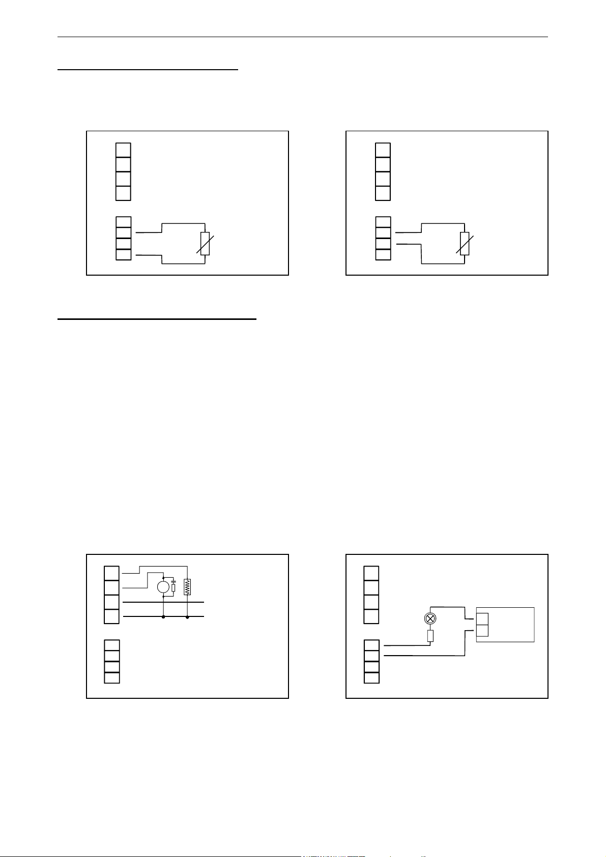
3.4.1. Connection of the relay outputs 3.4.2 Connection of output 3
(NPN-output, switching to ground)
1
2
3
4
5
6
7
8
Connection of consumer loads (motor, heater) Connection of consumer loads (lamp)
M
N
230V~
L
1
2
3
4
5
6
7
8
+
_
Supply:
for load

E33.0.31.6C-02 Manual for connection and operation of the GIR230 Pt1000 / DIF and GIR230 NTC /DIF Page 6 of 14
4. Configuration of the device
Please note: When you are configuring the device and don’t press any button for more than 60 sec. the
configuration of the device will be cancelled. The changes you made will not be saved and will be lost!
Hint: The buttons 2 and 3 are featured with a ‘roll-function‘. When pressing the button once the value will be raised
(button 2) by one or lowered (button 3) by one. When holding the button pressed for longer than 1 sec. the
value starts counting up or down, the counting speed will be raised after a short period of time.
The device also features a ‘overflow-function‘, when reaching the upper limit of the range, the device switches
to the lower limit, vice versa.
4.1. Selecting an input signal type
- Turn the device on and wait until it completed its built-in segment test.
- Press button 2 for >2 sec.
The display will show “Unit“ (the unit you want to measure).
- Use button 2 and button 3 to select the desired Unit °C or °F.
- Validate the selected value by pressing button 1. The display shows “Unit“ again.
- Press button 1 again, the display will show “FiLt“ (digital filter).
- Use button 2 and button 3 to select the desired filter [in sec.].
Selectable values: 0.01 ... 2.00 sec.
Explanation: this digital filter is a digital replica of a low pass filter.
Button 1 Button 2 Button 3
- Press button 1 to validate your value, the display shows “FiLt“ again.
Now your device is adjusted to your temperature probe. Now the only thing left to do is to adjust the outputs
of the device.
- Press button 1 again, the display will show “outP“. (output)
For offset and slope adjustment please read on in chapter 6.

E33.0.31.6C-02 Manual for connection and operation of the GIR230 Pt1000 / DIF and GIR230 NTC /DIF Page 7 of 14
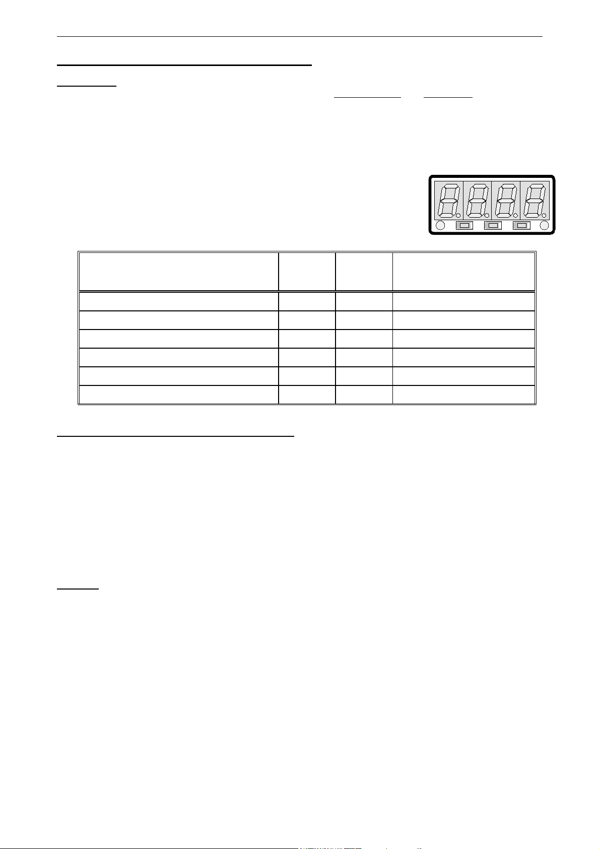
4.2. Selection of the output function
- The Display now shows “outP“. (output)
- Use button 2 and button 3 (middle and right button) to select the desired output-function.
The following table shows how the outputs will be configured on your selection.
Description
No output, device is
used as display device
2-point-controller
3- point-controller
2- point-controller with
min-/max-alarm
3- point-controller with
min-/max-alarm
min-/max-alarm
- Press button 1 to validate the selected output function. The display shows “outP“ again.
When selected ‘no‘ as desired output you finished configuring your device. Press button 1 to switch over to
display the measuring value.
When selected a different output you have to configure the preferred states and delay time of the outputs
and the switch and alarm points.
To select as
output
no
2P Switch-function 1
3P Switch-function 1 Switch-function 2 Switch-function 1
2P.AL Switch-function 1
3P.AL Switch-function 1 Switch-function 2
AL
Output 1
(Relay 1)
off off off
Max-alarm,
inverted
Output 2
(Relay 2)
Switch-function 1,
inverted
Min-/Max-alarm,
inverted
Min-alarm,
inverted
Output 3
(out 3)
Switch-function 1
Min-/Max-alarm,
inverted
Min-/Max-alarm,
inverted
Min-/Max-alarm,
inverted
See
chapter
--
5.1
5.1
5.2
5.2
5.3
Depending on your output function setting, it may be possible that one or more settings described below
won’t be available.
- When pressing button 1 again, the device will display “1.dEL“ (delay of switch function 1).
- Use button 2 and button 3 to set the desired value for switch function 1.
Hint: The selected value [0.01 ... 2.00] will be in seconds.
- Press button 1 to validate the selection. The display shows “1.dEL“ again.
- Press button 1 again, the device will display “1.Err“ (error = preferred state of switch function 1).
- Use button 2 and button 3 (middle and right button) to set the desired output state in case of an error.
Display Preferred state of the output Note
off
on
- Press button 1 to validate the selection. The display shows “1.Err“ again.
- In case you selected a 3-point-controller you have to make the following settings similar to the settings
you already made for output 1:
“2.dEL“ (delay of output 2), “2.Err“ (preferred state of output 2).
Now you finished configuring the output functions. Depending on the selected output function you have to
make the settings for switching and alarm points. See description in chapter „switchpoints and alarmboundaries“ for further information.
Inactive in case of an error
Active in case of an error
Hint: The settings for the switching and alarm points can be made later in an extra menu (see chapter 5)
E33.0.31.6C-02 Manual for connection and operation of the GIR230 Pt1000 / DIF and GIR230 NTC /DIF Page 8 of 14
5. Switchpoints and alarm-boundaries
Please note: The settings of the switchpoints will be cancelled, when no button was pressed for more than
60 sec. changes you may have made already won‘t be saved and will be lost!
Hint: The buttons 2 and 3 are featured with a ‘roll-function‘. When pressing the button once the value will be raised
(button 2) by one or lowered (button 3) by one. When holding the button pressed for longer than 1 sec. the
value starts counting up or down, the counting speed will be raised after a short period of time.
The device also features an ‘overflow-function‘, when reaching the upper limit the device switches to the lower
limit, vice versa.
- When pressing button 1 for >2 sec. the menu to select the switchpoints and
alarm-boundaries will be called.
- Depending on the configuration you have made in the „output“ menu you
will get different display values. Please follow the specific chapter for further information.
Button 1 Button 2 Button 3
Description
No output, device is used as display device
2- point-controller
3- point-controller
2- point-controller with min-/max-alarm
3- point-controller with min-/max-alarm
min-/max-alarm
To select as
output
no
2P
3P
2P.AL
3P.AL
AL
Go on in
chapter
--
5.1
5.1
5.2
5.2
5.3
Note
5.1. 2- point-controller, 3- point-controller
This chapter describes how to configure the device as a 2-point-controller or 3-point-controller.
This instruction demands that you selected “2P“ or “3P“ as your desired output function.
- Press button 1
- Use button 2 and button 3 to set the desired value, the device’s output 1 should be turning on.
- Press button 1 to validate your selection. The display shows “1.on“ again.
- When pressing button 1 again, the device will be displaying “1.off“. (turn-off-point of output 1)
- Use button 2 and button 3 to set the desired value, the device’s output 1 should be turning off.
(when not already done).
The device will be displaying “1.on“ (turn-on-point of output 1).
- Press button 1 to validate your selection. The display shows “1.off“again.
Example: You want to control the temperature of a heating coil, with a hysteresis of +2°C, to 100°C.
Therefore you will have to select the turn-on-point “1.on“ to 100°C and the turn-off-point to
“102°C“. When your heating coil temperature falls below 100°C it will be turned on. When the
temperature rises above 102°C the heating coil will be turned off.
Note: Depending on the inertia of your heating coil an overshooting of the temperature may be
possible.
When selected ‘2-point-controller‘ you finished configuring your device. Press button 1 to switch over to display the measuring value.
When selected ‘3-point-controller‘ please follow the instructions given below.
-- Press button 1
(when not already done).
The device will be displaying “2.on“ (turn-on-point of output 2).
- Use button 2 and button 3 to set the desired value, the device’s output 2 should be turning on.
- Press button 1 to validate your selection. The display shows “2.on“ again.
- When pressing button 1 again, the device will be displaying “2.off“. (turn-off-point of output 2)
- Use button 2 and button 3 to set the desired value, the device’s output 2 should be turning off.
- Press button 1 to validate your selection. The display shows “2.off“again.

E33.0.31.6C-02 Manual for connection and operation of the GIR230 Pt1000 / DIF and GIR230 NTC /DIF Page 9 of 14
Now you finished configuring the switching points of your device. Press button 1 to switch over to display the
measuring value.
5.2. 2-point-controller with alarm function, 3-point-controller with alarm function
This chapter describes how to configure the device as a 2-point-controller with alarm function or 3-pointcontroller with alarm function. This instruction demands that you selected “2P.AL“ or “3P.AL“ as your desired
output function.
- Press button 1
(when not already done).
The device will be displaying “1.on“ (turn-on-point of output 1).
- Use button 2 and button 3 to set the desired value, the device’s output 1 should be turning on.
- Press button 1 to validate your selection. The display shows “1.on“ again.
- When pressing button 1 again, the device will be displaying “1.off“. (turn-off-point of output 1)
- Use button 2 and button 3 to set the desired value, the device’s output 1 should be turning off.
- Press button 1 to validate your selection. The display shows “1.off“again.
Example: You want to control the temperature of a cooling chamber between –20°C and –22°C.
Therefor you will have to select –20°C for the turn-on-point 1 “1.on“ and –22°C for the turn-offpoint 1 “1.off“. When the temperature rises above –20°C the device turns its output 1 on, when
falling below –22°C the device will turn its output 1 off .
Note: Depending on the inertia of your cooling circuit an overshooting of the temperature may be possible.
.
When selected '3-point-controller with alarm function', you have to select the switching points for the second
switching function (“2.on“, “2.off“). Configuring these settings like the first switching function.
After that the alarm outputs have to be configured.
- When pressing button 1, the device will be displaying “AL.Hi“. (maximum alarm-value)
- Use button 2 and button 3 to set the desired value, the device should turn on its maximum-alarm.
- Press button 1 to validate your selection. The display shows “AL.Hi“ again.
- When pressing button 1 again, the device will be displaying “AL .Lo“. (minimum alarm-value)
- Use button 2 and button 3 to set the desired value, the device should turn on its minimum-alarm
- Press button 1 to validate your selection. The display shows “AL.Lo“ again.
- When pressing button 1 again, the device will be displaying “A. dEL“. (delay of the alarm-function)
- Use button 2 and button 3 to set the desired delay of the alarm-function.
Note: The unit of the value to be set [0 .. 9999] is in seconds. The device will turn on the alarm after
the minimum or maximum alarm value was active for the delay-time you have set.
- Press button 1 to validate the delay time. The display shows “A.dEL“ again.
Example: You want to have an alarm monitoring for the cooling chamber mentioned above. The alarms
should start when the temperature will be rising above –15°C or falling below –30°C.
Therefore you have to select –15°C for the maximum alarm-value “Al.Hi“ and –30°C for the minimum alarm-value “AL.Lo“.
The alarm will be starting after the temperature rises above –15°C and stays above –15°C for the
entered delay time or after it had been falling below –30°C and stays below –30°C for the entered
delay time.
Please note that the alarm-outputs are inverted! This means, that the output will be active if there is no
alarm!
Now you finished configuring your device. Press button 1 to switch over to display the measuring value.

E33.0.31.6C-02 Manual for connection and operation of the GIR230 Pt1000 / DIF and GIR230 NTC /DIF Page 10 of 14
5.3. Minimum/maximum-alarm
This chapter describes how to configure the device‘s alarm boundaries for min-/max-alarm-monitoring.
This instruction demands that you selected “AL“ as your desired output function.
- Press button 1
- Use button 2 and button 3 to set the desired value, the device should turn on its maximum-alarm.
- Press button 1 to validate your selection. The display shows “AL.Hi“ again.
- When pressing button 1 again, the device will be displaying “AL .Lo“. (minimum alarm-value)
- Use button 2 and button 3 to set the desired value, the device should turn on its minimum-alarm
- Press button 1 to validate your selection. The display shows “AL.Lo“ again.
- When pressing button 1 again, the device will be displaying “A. dEL“. (delay of the alarm-function)
- Use button 2 and button 3 to set the desired delay of the alarm-function.
Note: The unit of the value to be set [0 .. 9999] is in seconds. The device will turn on the alarm after
- Press button 1 to validate the delay time. The display shows “A.dEL“ again.
Example: You want to have a temperature alarm-monitoring of a greenhouse. The alarm should start when
the temperature rises above 50°C or falls below 15°C. Therefore your settings will be 50°C for the
maximum alarm-value “AL.HI“ and 15°C for the minimum alarm-value “AL.Lo“.
The alarm will be starting after the temperature rises above 50°C and stays above 50°C for the
entered delay time or after it had been falling below 15°C and stays below 15°C for the entered
delay time.
Please note that the alarm-outputs are inverted! This means, that the output will be active when there is no
Now you finished configuring your device. Press button 1 to switch over to display the measuring value.
(when not already done)
minimum or maximum alarm value was active for the delay-time you have set.
, the device will be displaying “AL.Hi“. (maximum alarm-value)
alarm!
6. Min-/Max-alarm display
If a output function with alarm (out = 2P.AL, 3P.AL or AL) is selected and there is an alarm condition the display
alternates between measuring value and AL.Lo or AL.Hi
Min.-alarm: approx. all 2 sec. AL.Lo will be shown in the display
Max.-alarm: approx. all 2 sec. AL.Lo will be shown in the display
7. Displaying the measuring value of input 1 or input 2
The display will normally show the difference value (input 1 – input 2).
Also the measuring value of input 1 and input 2 can be called for a short time.
Calling of meas. value input 1: press button 1 shortly the device will display“INP.1“ briefly, after that the
meas. value of input 1 is displayed for about 2 sec.
Calling of meas. value input 2: press button 1 shortly 2-times the device will display“INP.2“ briefly, after that the
meas. value of input 2 is displayed for about 2 sec.
8. Min-/max-value storage
The device features a minimum/maximum-value storage. In this storage the highest and lowest measured value
are saved.
Calling of the minimum-value press button 3 shortly the device will display “Lo“ briefly, after that
the min-value is displayed for about 2 sec.
Calling of the maximum-value press button 2 shortly the device will display “Hi“ briefly, after that
the max-value is displayed for about 2 sec.
Erasing of the min/max values press button 2 and 3 for 2 sec. The device will display “CLr“ briefly, after
that the min/max-values are set to the current displayed value.

E33.0.31.6C-02 Manual for connection and operation of the GIR230 Pt1000 / DIF and GIR230 NTC /DIF Page 11 of 14
9. Offset- and slope-adjustment
The offset and slope-adjustment function can be used for compensating the tolerance of the used probes.
Please note: The settings of the offset- / slope-adjustment will be cancelled, when no button was pressed
for more than 60 sec. Changes you may have made already won‘t be saved and will be lost!
Hint: The buttons 2 and 3 are featured with a ‘roll-function‘. When pressing the button once the value will be raised
(button 2) by one or lowered (button 3) by one. When holding the button pressed for longer than 1 sec. the
value starts counting up or down, the counting speed will be raised after a short period of time.
The device also features a ‘overflow-function‘, when reaching the upper limit the device switches to the lower
limit, vice versa.
- Turn on the device and wait after it finished its built-in segment test.
- Press button 3 > 2 sec.
The device will be displaying “OFS.1“ (offset of input 1).
- Use button 2 and button 3 for setting the desired zero point offset-value.
The input of the offset will be in digits.
Button 1 Button 2 Button 3
The value that had been set will be subtracted from the measured value of input 1.
- Press button 1 to validate your selection. The display shows “OFS.1“ again.
- When pressing button 1 again, the device will be displaying “SCA.1“. (scale 1 = slope of input 1)
- Use button 2 and button 3 to select the desired slope-adjustment.
The slope adjustment will be entered in %. The value displayed can be calculated like this:
Displayed value 1 = (measured value input 1 – zero point offset 1) * (1 + slope adjustment 1 [% / 100]).
Example: The setting is 2.00 => the slope has risen 2.00% => slope = 102%.
When measuring a value of 1000 (without slope-adjustment) the device would display 1020 (with slope
adjustment of 102%)
- Press button 1 to validate the selection of the slope-adjustment. The display shows “SCA.1“ again.
- When pressing button 1 again, the device will be displaying “OFS.2“. (offset of input 2)
- Use button 2 and button 3 for setting the desired zero point offset-value.
The input of the offset will be in digits.
The value that had been set will be subtracted from the measured value of input 2.
- Press button 1 to validate your selection. The display shows “OFS.2“ again.
- When pressing button 1 again, the device will be displaying “SCA.2“. (scale 2 = slope of input 2)
- Use button 2 and button 3 to select the desired slope-adjustment.
The slope adjustment will be entered in %. The value displayed can be calculated like this:
Displayed value 2 = (measured value input 2 – zero point offset 2) * (1 + slope adjustment 2 [% / 100]).
Example: The setting is 2.00 => the slope has risen 2.00% => slope = 102%.
When measuring a value of 1000 (without slope-adjustment) the device would display 1020 (with slope
adjustment of 102%)
- Press button 1 to validate the selection of the slope-adjustment. The display shows “SCA.2“ again.
Now you finished configuring the device’s offset and slope adjustment. Press button 1 to switch over to display the measuring value.
Example for offset- and slope-adjustment:
Example: Connecting a temperature probe (offset deviation depending on using long wires between probe and device)
The device displays the following values (without offset- or slope-adjustment): at 0°C = 2°C, at 100°C = 102°C
Therefore you calculated: zero point: 2
slope: 102 – 2 = 100 (=>deviation = 0)
You have to set: offset = 2
scale = 0.00
(= zero point deviation)

E33.0.31.6C-02 Manual for connection and operation of the GIR230 Pt1000 / DIF and GIR230 NTC /DIF Page 12 of 14
10. Error codes
When detecting an operating state which is not permissible, the device will display an error code
The following error codes are defined:
Err.1: Exceeding of the measuring range
Indicates that the valid measuring range of the device has been exceeded.
Possible causes: - Temperature too high.
- sensor broken.
- sensor is wrong connected
Remedies: - The error-message will be reset if the input signal is within the limits.
- check probe and device configuration.
Err.2: Value below the measuring range
Indicates that the value is below the valid measuring range of the device.
Possible causes: - Temperature is too low
- sensor shorted
- sensor is wrong connected
Remedies: - The error-message will be reset if the input signal is within the limits.
- check probe and device configuration.
Err.7: System-error
The device features an integrated self-diagnostic-function which checks essential parts of the device permanently. When detecting a failure, error-message Err.7 will be displayed.
Possible causes: - Valid operating temperature range has been exceeded or is below the
valid temperature range.
- Device defective.
Remedies: - Stay within valid temperature range.
- Exchange the defective device.
Err.9: Sensor defective
The device features a built in diagnose function for the connected probe or transducer.
When this function is detecting an error the message Err.9 will be displayed.
Possible causes: - probe broken or shorted
- sensor is wrong connected
Remedies: - check probe and exchange defective probe, if necessary.
Er.11: Value could not be calculated
Indicates a measuring value, needed for calculation of the display value, is faulty or out of range.
Possible causes: - one input signal has transgressed the measuring range or is not
connected
Remedies: - check probe and exchange defective probe, if necessary.

E33.0.31.6C-02 Manual for connection and operation of the GIR230 Pt1000 / DIF and GIR230 NTC /DIF Page 13 of 14
11. Specification
Absolute maximum ratings:
Connection
between
Supply voltage 3 and 4
Relay output
1 and 2
Output 3
(NPN, open collector)
Input temperature
probe
1 and 3,
2 and 3
5 and 6 0 V
6 and 8, 7 and
8, 6 and 7
Absolute maximum ratings must not be exceeded (not even for a short period of time)!
GIR 230 Pt1000 / DIF GIR 230 NTC / DIF
Measuring inputs: Pt1000 (2-wire) NTC (2-wire)
Display range: -200 ... +850 °C
Difference temperature: -1050 ... +1050 °C
Accuracy: < 0.5% FS ±1Digit
Max allowed output resistance: 20 Ohm
Meas. frequency: approx. 4 measures / sec.
Performance data Limit values
min. max. min. max.
207 V
AC
244 V
AC
0 V
AC
DC
0 Ω∞ Ω
or -328 ... +1562 °F
or -1890 ... +1890°F
(at nominal temperature)
-40.0 ... +120.0 °C
-160.0 ... +160.0 °C
253 V
AC
5 A,
ohm resistive load
28 VDC,
I < 30mA
Notes
No active signal allowed
or -328 ... +1562 °F
or -288.0 ... +288.0 °F
Outputs: 2 relay outputs, switching to 230V 1 NPN-output (open collector), switching to ground
Relay output: closing contact
breaking capacity: 5A, 230VAC, resistive load
NPN-output: NPN, Open Collector
breaking capacity: 30mA, max. 28VDC
Output functions: 2-point, 3- point, 2- point with alarm, 3- point with alarm, min-/max-alarm.
Switching points: arbitrary
Switching delay: arbitrary: 0.01 ... 2.00 sec.
Alarm delay: arbitrary: 1 ... 9999 sec.
Display: approx. 10 mm high, 4-digit red LED-display
Operation: 3 push buttons
Power supply: 230V, 50/60Hz
Power consumption: approx. 2VA
Nominal temp.: 25°C
Operating ambient: -20 to +50°C
Relative Humidity: 0 to 80 %RH (non condensing)
Storing temp.: -30 to +70°C
Enclosure: main housing: fibre-glass-reinforced noryl
front view-panel: polycarbonate
Dimensions: 24 x 48 mm (front-panel cut out).
Installation depth: approx. 65 mm (incl. screw-in/plug-in clamps)
Panel Mounting: via VA-spring-clip.
Panel thickness: possible from 1 to approx. 10 mm possible.
Panel cut-out: 21.7+0.5 x 45+0.5 mm (H x W)
Connection: via screw-in/plug-in clamps: 4-pol. for mains-supply and relay connection
4-pol. for measuring input and alarm output. Conductor cross-selection: from 0.14 to
1.5 mm² (input/alarm) and 0.14 to 2.5mm² (mains/relay).
Protection class: front IP54
EMC: EN61326 +A1 +A2 (appendix A, class B), additional errors: < 1% FS
When connecting long leads adequate measures against voltage surges have to be
taken.
.

E33.0.31.6C-02 Manual for connection and operation of the GIR230 Pt1000 / DIF and GIR230 NTC /DIF Page 14 of 14
 Loading...