

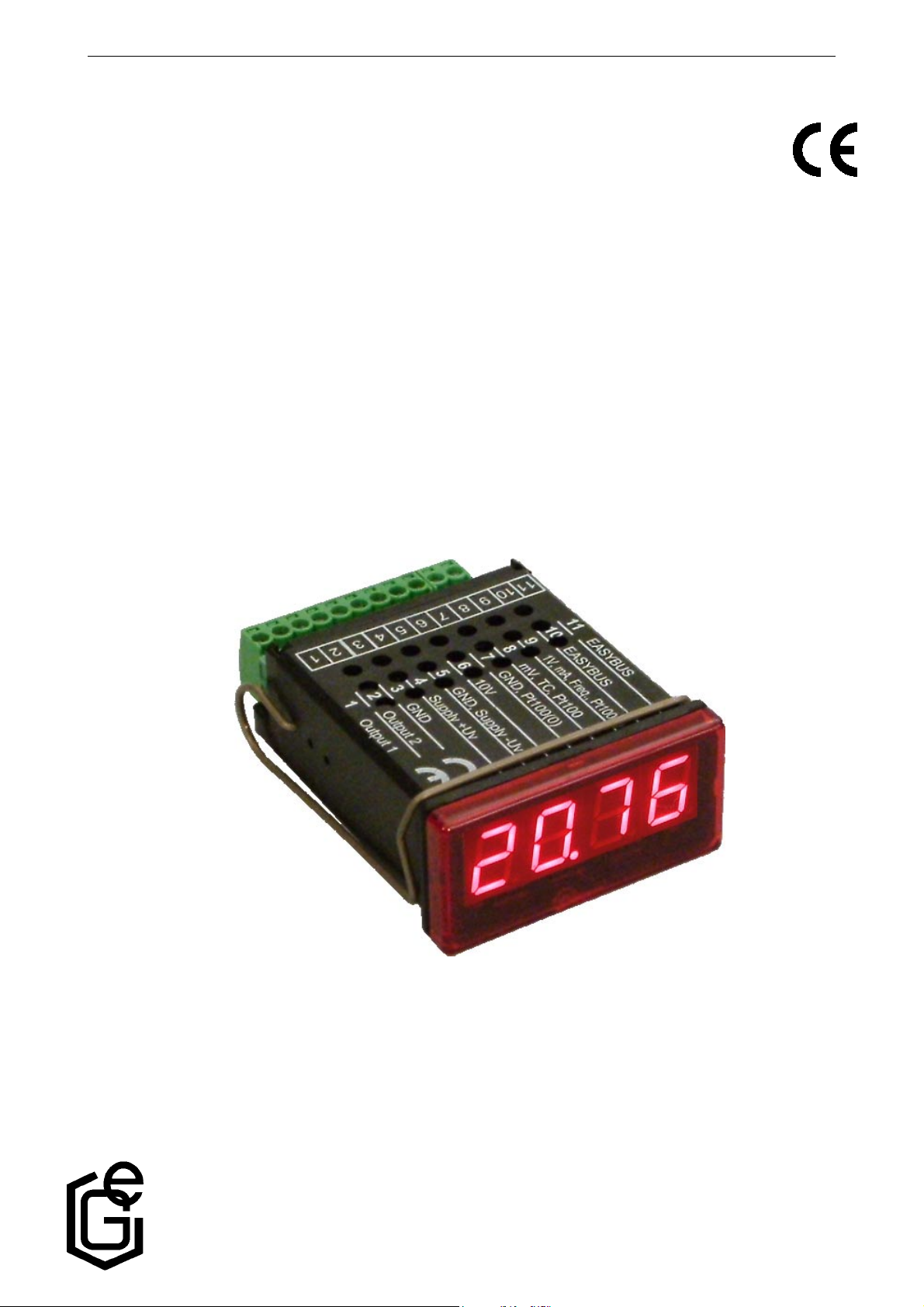
E31.0.21.6C-01 Manual for connection and operation of the GIA 20 EB / PK page 1 of 20
Manual for connection and operation of
GIA 20 EB / PK
as of version 2.5
GREISINGER
electronic GmbH
D - 93128 Regenstauf, Hans-Sachs-Straße 26
Phone: 0049 9402 / 9383-0, Fax: 0049 9402 / 9383-33, e-mail: info@greisinger.de

E31.0.21.6C-01 Manual for connection and operation of the GIA 20 EB / PK page 2 of 20
I N D E X
1. SAFETY REGULATIONS .......................................................................................................................................... 3
2. INTRODUCTION ........................................................................................................................................................4
3. ELECTRIC CONNECTION ....................................................................................................................................... 5
3.1. Terminal assignment................................................................................................................................................ 5
3.2. Connection data .......................................................................................................................................................5
3.3. Connecting an input signal.......................................................................................................................................5
3.3.1. Connecting a resistance sensor .........................................................................................................................5
3.3.2. Connecting a 4-20mA transmitter in 2-wire-technology ..................................................................................6
3.3.3. Connecting a 0(4)-20mA transmitter in 3-wire-technology.............................................................................. 6
3.3.4. Connecting a 0-1V, 0-2V or 0-10V transmitter in 3-wire-technology.............................................................. 6
3.3.5. Connecting a 0-1/2/10V or 0-50mV transmitter in 4-wire-technology............................................................. 6
3.3.6. Connecting a frequency- or rotation-signal....................................................................................................... 7
3.3.7. Connecting a counter signal.............................................................................................................................. 8
3.4. Connecting switching outputs.................................................................................................................................. 9
3.4.1. Connection with configured low-side-switching output (NPN output, switching to GND) .............................9
3.4.2. Connection with configured high-side-switching output (PNP output, switching to +Us)............................... 9
3.4.3. Connection with configured push-pull-switching output................................................................................ 10
3.5. Common wiring of several GIA20EB ...................................................................................................................10
4. CONFIGURATION OF THE DEVICE ................................................................................................................... 11
4.1. Installing the software............................................................................................................................................ 11
4.2. Operating the software........................................................................................................................................... 11
4.3. Manual selection of the output function ................................................................................................................12
5. SWITCHPOINTS AND ALARM-BOUNDARIES.................................................................................................. 14
5.1. 2-point-controller, 3-point-controller..................................................................................................................... 14
5.2. 2-point-controller with alarm function...................................................................................................................15
5.3. Minimum/maximum-alarm (individual or common)............................................................................................ 16
6. OFFSET- AND SLOPE-ADJUSTMENT ................................................................................................................. 16
7. MIN-/MAX-VALUE STORAGE: ............................................................................................................................. 17
8. SERIAL INTERFACE:.............................................................................................................................................. 17
9. ERROR CODES ......................................................................................................................................................... 17
10. SPECIFICATION..................................................................................................................................................... 19
11. DISPOSAL NOTES.................................................................................................................................................. 20
E31.0.21.6C-01 Manual for connection and operation of the GIA 20 EB / PK page 3 of 20
1. Safety regulations
This device was designed and tested considering the safety regulations for electronic measuring devices.
Faultless operation and reliability in operation of the measuring device can only be assured if the General
Safety Measures and the devices specific safety regulations mentioned in this users manual are considered.
1. Faultless operation and reliability in operation of the measuring device can only be assured if the device
is used within the climatic conditions specified in the chapter “Specifications“
2. Always disconnect the device from its supply before opening it. Take care that nobody can touch any of
the unit‘s contacts after installing the device.
3. Standard regulations for operation and safety for electrical, light and heavy current equipment have to be
observed, with particular attention paid to the national safety regulations (e.g. VDE 0100).
4. When connecting the device to other devices (e.g. the PC) the interconnection has to be designed most
thoroughly, as internal connections in third-party devices (e.g. connection of ground with protective earth)
may lead to undesired voltage potentials.
5. The device must be switched off and must be marked against using again, in case of obvious malfunctions of the device which are e.g.:
- visible damage.
- the device is not working as prescribed.
- storing the device under inappropriate conditions for longer time.
When not sure, the device should be sent to the manufacturer for repairing or servicing.
ATTENTION: When running electric devices, parts of them will always be electrically
live. Unless the warnings are observed serious personal injuries or damage to property may result. Skilled personnel only should be allowed to work with this device. For
trouble-free and safe operation of the device please ensure professional transport,
storage, installation and connection as well as proper operation and maintenance.
SKILLED PERSONNEL
Are persons familiar with installation, connection, commissioning and operation of the product and have
professional qualification relating to their job.
For example:
• Training or instruction and qualifications to switch on or off, isolate, ground and mark electric circuits and
devices or systems.
• Training or instruction according to the state.
• First-aid training.
ATTENTION:
Do NOT use this product as safety or emergency stopping device, or in any other
application where failure of the product could result in personal injury or material
damage.
Failure to comply with these instructions could result in death or serious injury and
material damage.
E31.0.21.6C-01 Manual for connection and operation of the GIA 20 EB / PK page 4 of 20
2. Introduction
The GIA 20 EB / PK is a microprocessor controlled displaying, monitoring
and controlling device.
The device is supporting one universal interface for the connection of:
- Standard transmitter signals (0-20mA, 4-20mA, 0-50mV, 0-1V,
0-2V and 0-10V )
- Resistance sensors
- Frequency (TTL and switching contact)
The device features two switching outputs, which can be configured as
2-point-controller, 3-point-controller, 2-point-controller with min./max. alarm,
common or individual min./max. alarm.
The state of the switching outputs is displayed with two LED’s beneath the
front 4-digit LED-display.
The left LED displays the state of the 1st output, the right LED displays the state of the 2nd output.
Furthermore the device supports one EASBus-interface so that the device can communicate with a host
computer via an interface converter and makes the device to a full functions EASBus-module.
When leaving our factory the GIA20EB / PK has been subjected to various inspection tests and is completely
calibrated.
Before the GIA20EB / PK can be used, it has to be configured for the customer’s application.
Hint: In order to avoid undefined input states and unwanted or wrong switching processes, we sug-
gest to connect the device’s switching outputs after You have configured the device properly.
For configuring the GIA20EB please proceed as follows:
- Disassemble the red front plate (see sketch).
- Connect the device to its supply
(see chapter 3 ‘Electric connection‘).
- Switch on the supply voltage and wait until the device completed its
built-in segment test .
- Adjust the device to the input signal required. Follow the instructions
in chapter 4 ‘Input configuration‘
- Follow the instructions given in chapter 5 ‘Output and alarm
configuration‘ to configure the outputs of the GIA20EB.
- Reassemble the red front plate.
- Connect the device properly (see chapter 3 'Electric connection‘)
E31.0.21.6C-01 Manual for connection and operation of the GIA 20 EB / PK page 5 of 20
3. Electric connection
Wiring and commissioning of the device must be carried out by skilled personnel only.
In case of wrong wiring the device may be destroyed. We can not assume any warranty in case of
wrong wiring of the device.
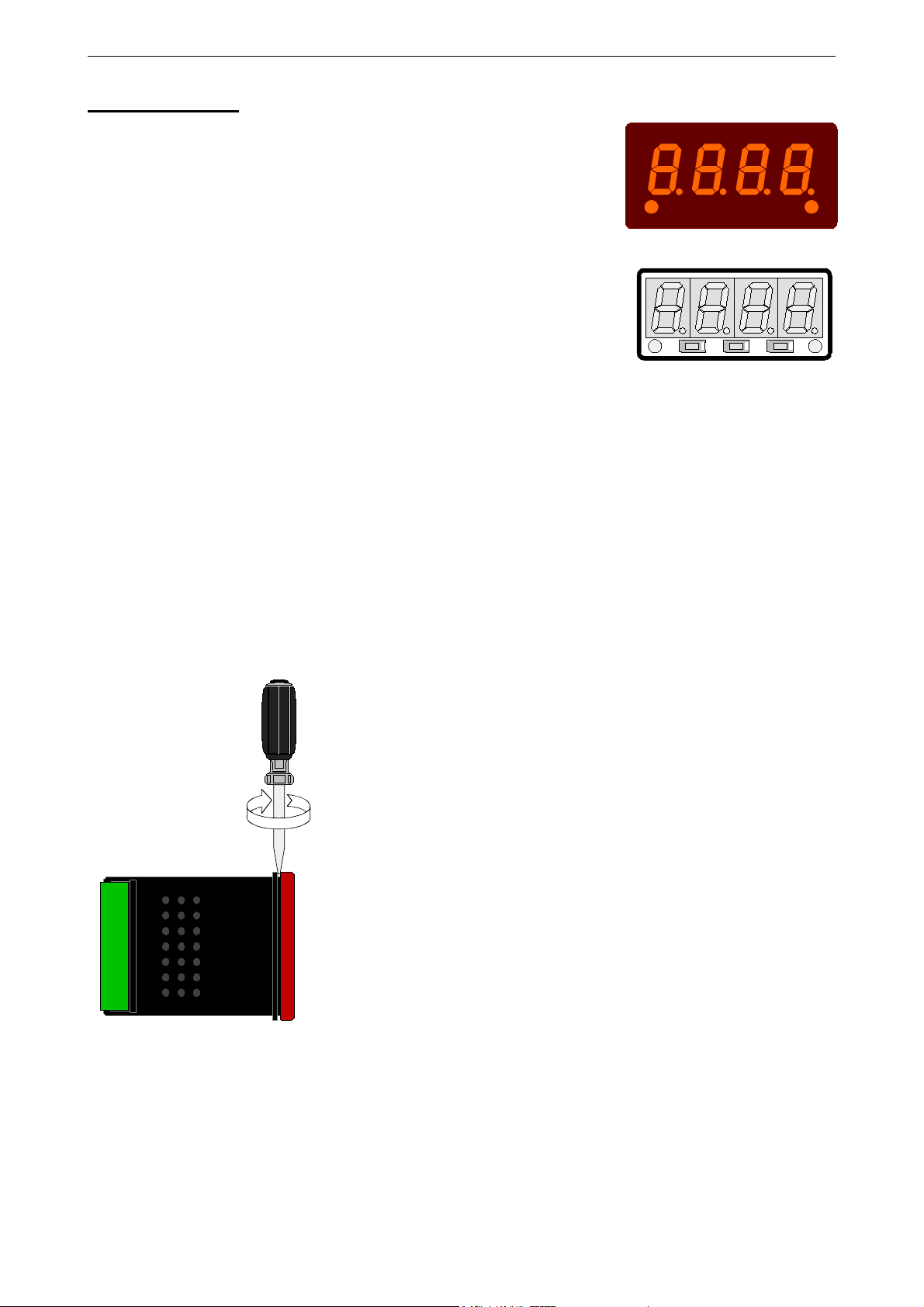
3.1. Terminal assignment
11
EASYBus interface
10
EASYBus interface
9
Input: 0-1V, 0-2V, mA, frequency, resistance sensor
8
Input: 0-50mV, resistance sensor
7
Input: GND, resistance sensor
6
Input: 0-10V
5
Supply voltage: GND
4
Supply voltage: +Us
3
Switching output: GND
2
Switching output: 2
1
Switching output: 1
(+Uv)
Hint: The contacts 3, 5 and 7 are connected internally.
11
10
98765 3214
11
EASYBUS
10
EASYBUS
9
1V, mA, Freq., Pt100(0)
8
mV, TC, Pt100
7
GND, Pt100(0)
6
10V
5
GND, Supply -Uv
4
Supply +Uv
3
GND
2
Output 2
1
Output 1
3.2. Connection data
Between
terminals
Supply voltage 4 and 5 9 V 28 V 0 V 30 V
NPN
Switching output
1 and 2
1 and 3,
2 and 3
PNP
Input mA 0 mA 20 mA 0 mA 30 mA
Input 0-1(2)V, Freq., ...
9 and 7
Input 0-50mV, TC, ... 8 and 7 0 V 3.3 V -1 V
Input 0-10V 6 and 7 0 V 10 V -1 V 20 V
These limits must not be exceeded (not even for a short time) !
typical limitations
min. max. min. max.
30V,
I<1A
I<200mA
0 V 3.3 V -1 V
30 V,
I<10mA
10 V,
I<10mA
notes
Not short circuit protected
Not short circuit protected
3.3. Connecting an input signal
Please take care not to exceed the limitations of the inputs when connecting the device as this may lead
to destruction of the device:
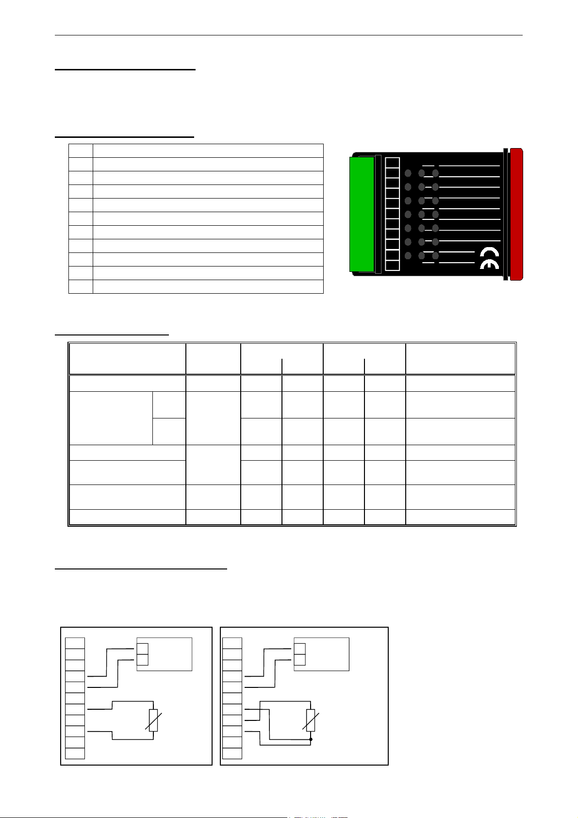
3.3.1. Connecting a resistance sensor
Netzteil:
+
_
9-28 VDC
4
5
7
R
9
Resistance measurement (2-wire) Resistance measurement (3-wire)
0-3900 Ohm
4
5
7
8
9
Netzteil:
+
_
9-28 VDC
R
20,0 - 390,0 Ohm

E31.0.21.6C-01 Manual for connection and operation of the GIA 20 EB / PK page 6 of 20
3.3.2. Connecting a 4-20mA transmitter in 2-wire-technology
Supply
+
_
9-28 VDC
4
5
4-20mA
+Uv
Transmitter
7
9
-Uv
+
_
for Transmitter
Supply
4
5
9
with individual transmitter supply without individual transmitter supply
3.3.3. Connecting a 0(4)-20mA transmitter in 3-wire-technology
Supply
+
_
9-28 VDC
4
5
7
9
+Uv
0(4)-20mA
Sig.
Transmitter
-Uv
+
_
for Transmitter
Supply:
4
5
9
+
_
9-28 VDC
+Uv
Transmitter
-Uv
+
_
9-28 VDC
+Uv
0(4)-20mA
Sig.
Transmitter
-Uv
Supply
4-20mA
Supply
with individual transmitter supply without individual transmitter supply
3.3.4. Connecting a 0-1V, 0-2V or 0-10V transmitter in 3-wire-technology
Supply
+
_
9-28 VDC
4
5
10V
6
7
1V / 2V
9
+Uv
Sig.
Transmitter
-Uv
+
_
for Transmitter
Supply
4
5
10V
6
1V / 2V
9
with individual transmitter supply without individual transmitter supply
3.3.5. Connecting a 0-1/2/10V or 0-50mV transmitter in 4-wire-technology
Supply
+
_
9-28 VDC
4
5
10V
6
7
50mV
8
1V / 2V
9
+Uv
Sig+
Transmitter
Sig-
-Uv
+
_
for Transmitter
Supply
4
5
10V
6
7
50mV
1V / 2V
9
+
_
9-28 VDC
+Uv
Sig.
Transmitter
-Uv
+
_
9-28 VDC
+Uv
Sig+
Transmitter
Sig-
-Uv
Supply
Supply
(Note: Sig- and –Uv of the Transmitter must be the same potential)
with individual transmitter supply without individual transmitter supply

E31.0.21.6C-01 Manual for connection and operation of the GIA 20 EB / PK page 7 of 20
3.3.6. Connecting a frequency- or rotation-signal
When measuring frequency or rotation three different input signals can be selected in the device’s configuration.
There is the possibility of connecting an active signal (= TTL, ...), a passive sensor-signal with NPN
(= NPN-output, push-button, relay, ...) or PNP (= a PNP output switching to +Us, high-side push-button, ...).
When configuring the device with a NPN switching output, a pull-up-resistor (~11kΩ referring to +3.3V)
is connected internally. So when You use a device with NPN output You don‘t need to connect a resistor
externally.
When configuring the device with a PNP switching output, a pull-down resistor (~11kΩ referring to GND)
is connected internally. So when You use a device with PNP output You don‘t need a resistor externally.
It may be that your measuring-signal source needs the connection of an external resistor e.g. the pull-upvoltage of 3.3V is not enough for the signal source, or you want to measure in the top level frequency
range. In this case the input signal has to be treated like an active signal and you have to configure the
device as „TTL“.
Hint: when connecting the device You have to take care not to exceed the limits of the input
voltage respective the input current of the frequency-input.
Supply
+
_
9-28 VDC
4
5
7
9
+Uv
Transducer
Sig.
-Uv
+
_
for T rans ducer
Supply
4
5
9
+
_
9-28 VDC
+Uv
Transducer
Sig.
-Uv
Supply
Connection of a transducer (with separate power supply) Connection of a transducer (without separate power supply)
with TTL or PNP output and external resistor for current limitation. with TTL or PNP output and external resistor for current limitation.
Supply
+
_
9-28 VDC
4
5
7
9
+Uv
Sig.
-Uv
+
_
for T rans ducer
Transducer
Supply
4
5
9
+Uv
Sig.
-Uv
+
_
Supply
9-28 VDC
Transducer
Connection of a transducer (with separate power supply) with NPN output. Connection of a transducer (without separate power supply) with NPN output.
Supply
+
_
9-28 VDC
4
5
7
9
Rv
+Uv
Sig.
-Uv
+
_
for T rans ducer
Transducer
Supply
4
5
Rv
9
+Uv
Sig.
-Uv
+
_
Supply
9-28 VDC
Transducer
Connection of a transducer (with separate power supply) with NPN output Connection of a transducer (without separate power supply) with NPN output
and necessary external resistor and necessary external resistor.
Hint: Rv = 3kΩ (with power supply voltage = 12V) or 7kΩ (with power supply voltage = 24V), device configuration: Sens = TTL

E31.0.21.6C-01 Manual for connection and operation of the GIA 20 EB / PK page 8 of 20
Supply
+
_
9-28 VDC
4
5
7
Rv2
9
Rv1
+Uv
Sig.
-Uv
+
_
for T rans ducer
Transducer
Supply
4
5
7
9
Rv2
Rv1
+Uv
Sig.
-Uv
+
_
Netzteil:
9-28 VDC
Geber
Connecting of a transducer (with individual power supply) Connecting of a transducer (without individual power supply)
PNP output with external resistor wiring. PNP output and external resistor wiring.
Hint: Rv2 = 600Ω, Rv1 = 1.8kΩ (with power supply voltage = 12V) or 4.2kΩ (with power supply voltage = 24V), device config.: Sens = TTL
(Rv1 is a current limiting resistor and may be shorted if necessary. It should never exceed the mentioned value.)
3.3.7. Connecting a counter signal
When configuring the device you can select 3 different input signal modes similar to the connection of
frequency- and rotation-signals. The connection of a sensor-signal for a counter-signal is the same used
for the frequency- and rotation-signal.
Please use the wiring diagram given in chapter 3.3.6.
There is the possibility to reset the counter. When connecting contact 8 with GND (e.g. contact 7) the
counter will be reset. You can do this manually (e.g. with the help of a push-button) or automatically
(with one switching output of the device).
Hint: When connecting the device, take care not to exceed the limits of the input-voltage or the input-
current of the frequency input.
Supply:
+
_
9-28 VDC
4
5
7
8
9
ResetButton
+Uv
Transducer
Sig.
-Uv
manually reset the device with the help of a push-button
Supply
2
4
5
7
8
9
ResetButton
+
_
9-28 VDC
+Uv
Transducer
Sig.
-Uv
automatically resetting with the help of output 2 and
additional resetting the device via push-button
Hint: Output 2 has to be configured as NPN output
+Uv
Sig.
-Uv
+
_
Device
No.1
Device
No.2
2
4
5
7
8
9
2
4
5
7
8
9
Cascading of GIA20EB / PK
Hint for GIA20EB / PK:
Device 1 – Input signal like impuls-transmitter,
Output 2 configured as NPN output
Device 2 – Input-signal = switching-contact
Supply
9-28 VDC
Pulse
generator
E31.0.21.6C-01 Manual for connection and operation of the GIA 20 EB / PK page 9 of 20
3.4. Connecting switching outputs
The device features two switching outputs, with three different operating modes for each switching output, which are:
Low-Side: “GND-switching“ NPN output (open-collector)
The switching output is connected to the negative rail of the supply voltage (connection 3
or 5) when active (switching output on).
High-Side: “+Us-switching“ PNP output (open-collector)
The switching output is connected to the positive rail of the supply voltage (connection 4)
when active (switching output on).
Push-Pull: The switching output is connected to the negative rail of the supply voltage (connection 3
or 5) when inactive. When the switching output is active, it’s connected to the positive rail
of the supply voltage (connection 4).
In case of configuring one output as an alarm output, the output will be active in idle state (no alarm present). The output transistor opens or the push-pull output changes from +Us to –Us when an alarm condition occurred.
Hint: In order to avoid unwanted or wrong switching processes, we suggest to connect the
device’s switching outputs after you have configured the device’s switching outputs
properly.
Please take care that you must not exceed the limits of the voltage and of the maximum current
of the switching outputs (not even for a short period of time). Please take extreme care when
switching inductive loads (like coils or relays, etc.) because of their high voltage peaks, protective measures to limit these peaks have to be taken.
When switching large capacitive loads a series resistor for current limitation needed, because of
the high turn-on-current of high capacitive loads. The same applies to incandescent lamps,
whose turn-on-current is also quite high due to their low cold resistance.
3.4.1. Connection with configured low-side-switching output
+
1
2
3
4
5
Connection of consumer loads (relay and lamp) Connection of consumer loads (relay and lamp)
(without individual supply voltage) (with individual supply voltage)
3.4.2.
Connection with configured high-side-switching output
Relay
-
Supply
+
_
9-28 VDC
(NPN output, switching to GND)
+
1
2
3
4
5
Relay
-
+
_
+
_
9-28 VDC
(PNP output, switching to +Us)
Supply
for load
Supply
+
1
2
3
4
5
Connection of consumer loads (relay and lamp)
Relay
-
Supply
+
_
9-28 VDC
Hints:
Connections 3 and 5 are internally electrically connected.
When switching higher currents (> 50 mA) , the –Uv connection should not be attatched to the device (connection 3) but to
the -Us connection of the external power supply unit.
When doing this, you get rid off ground displacement.

E31.0.21.6C-01 Manual for connection and operation of the GIA 20 EB / PK page 10 of 20
3.4.3. Connection with configured push-pull-switching output
+
Semicond.-
1
2
3
4
5
Connection of a semiconductor-relay
Uin
relay
-
Supply
+
_
9-28 VDC
3.5. Common wiring of several devices
Inputs and outputs are not electrically isolated. When interconnecting several devices you have to make sure
that there is no potential displacement.
Make sure to observe the following points:
- When several devices are connected to the same power supply unit it is highly recommended to isolate the
sensors, measuring transducers etc.
- When the sensors, measuring transducers etc. are electrically connected, and you can’t manage to isolate
them, you should use separate electrically isolated power supply units for each devices. Please note, that
an electric connection may also be created via the medium to be measured (e.g. pH-electrodes and conductivity-electrodes in fluids).

E31.0.21.6C-01 Manual for connection and operation of the GIA 20 EB / PK page 11 of 20
4. Configuration of the device
Note: Except for the configuration of the output functions this device can
only be adjusted via the provided/downloaded software.
4.1. Installing the software
The setup can only be started if the dotNET 2.0 is already installed.
1. Execute the GIA 20 EB PK Configurator Setup.exe to install the software.
2. Select in Setup-Language our desired setting and confirm with OK
3. The Setup-Assistant appears helping you to install the software.
Follow the instructions of the Setup-Assistant.
4.2. Operating the software
After the software has started:
1. Select Configuration in the menu bar and choose your COM-
Port to which the interface converter is connected .
2. Enter the address of the GIA 20 EB / PK to the (address at
delivery is 0) into the input field.
3. After the successful connection to the GIA 20 EB / PK
all adjustment possibilities are available.
Under the tab Configuration the adjustments for the
input and display are monitored.
The configuration can be changed via choice boxes
and input fields.
Under the tab Characteristic the current characteristic
of the device can be loaded via the Import button.
The characteristic can be modified by clicking on the
desired field and entering the responding value.
Clicking on the Delete button will delete the complete
displayed table. This is a reasonable function if you
want to design a new characteristc.
You can add a new row or delete a single row with
the + and – buttons.
The entered characteristic is sent to the device if
the Program button is clicked.
4. Under the tab Output Settings all output functions of
the device can be configurated.
5. To complete the configuration the button Upload has
to be clicked. All adjustments are transferred and the
GIA 20 EB / PK restarts.
6. The current configuration can be saved for future
usage under File in the menu bar.

E31.0.21.6C-01 Manual for connection and operation of the GIA 20 EB / PK page 12 of 20
4.3. Manual selection of the output function
- Press button 2 for about 5 seconds to get to the menu for the manual selection of the output function.
The display shows “outP“ (output).
- Use button 2 and button 3 (middle or right button) to select the desired output-function.
Description
No output, device is used
as display unit
Function
Output 1 Output 2
--- ---
To select as
output
no
See chapter
--
2-point-controller digital
2-point-control-
---
2P
5.1
ler
3-point-controller digital
2-point-controller
2-point-controller with
Min-/Max-alarm
digital
2-point-
digital
2-pointcontroller
Min-/Max-alarm
3P
2P.AL
5.1
5.2
controller
Min-/Max-alarm,
common
Min-/Max-alarm,
individual
--- Min-/Max-alarm
Max-alarm Min-alarm
AL.F1
AL.F2
5.3
5.3
- Press button 1 to validate the selected output function. The display shows “outP“ again.
Depending on your output function setting, it may be possible that one or more settings described below
won’t be available.
- When pressing button 1 again, the device will display “1.dEL“ (delay of output 1).
- Use button 2 and button 3 to set the desired value for the switching-delay of output 1.
Hint: The selected value [0.01 ... 2.00] will be in seconds.
- Press button 1 to validate the selection. The display shows “1.dEL“ again.
- When pressing button 1 again, the device will display “1.out“ (kind of output 1).
- Use button 2 or button 3 (middle or right button) to select the desired output function.
Display Kind of output Note
nPn
PnP
Pu.Pu
NPN, open collector, switching GND
PNP, open collector, switching +Us
Low-Side
High-Side
Push-Pull
- Press button 1 to validate the selection. The display shows “ 1.out“ again.
- When pressing button 1 again, the device will display “1.Err“ (preferred state of output 1).
- Use button 2 and button 3 (middle or right button) to set the desired initial state in case of an error.
Display Preferred state of the output Note
off
Inactive in case of an error
Low-/High-side-switch is opened in case of an error.
Push-Pull-output is low in case of an error.
on
Active in case of an error
Low-/High-side-switch is closed in case of an error.
Push-Pull-output is high in case of an error.
- Press button 1 to validate the selection. The display shows “1.Err“ again.

E31.0.21.6C-01 Manual for connection and operation of the GIA 20 EB / PK page 13 of 20
- In case you selected a 3-point-controller you have to make the following settings similar to the settings
you already made for output 1:
“2.dEL“ (delay of output 2), “2.out“ (kind of output 2), “2.Err“ (preferred state of output 2).
- When pressing button 1 again, (only if you configured the device with min-/max-alarm)
the device will be displaying “A.out“ (kind of the alarm-output).
- Use button 2 or button 3 (middle or right button) to select the desired kind of the alarm-output.
Display Kind of the alarm-output Note
Switching output is closed (connected to
GND) as long there is no alarm-condition, and
is opened if there is an alarm-condition.
nPn
NPN, open collector, switching GND
Low-Side
Switching output is closed (is under voltage)
PnP
PNP, open collector, switching +Us
High-Side
as long there is no alarm-condition, and is
opened if there is an alarm-condition.
Switching output is high with no alarm-
Pu.Pu
Push-Pull
condition and changes to low if there is an
alarm-condition.
Please Note: The switching outputs are inverted when using them as alarm-outputs!
This means as long there is no alarm-condition, the switching output will be active! In case of an alarm-condition the output will become inactive!
Note: When using the output function “min-/max-alarm, individual“ the setting for kind of alarm output
is used for both alarm-outputs.
- Press button 1 to validate the selection. The display shows “ A.out“ again.
Depending on the selected output function you have to make the settings for switching and alarm points.
See description in chapter „switchpoints and alarm-boundaries“ for further information.
Hint: The settings for the switching and alarm points can be made later in an extra menu (see chapter 5)

E31.0.21.6C-01 Manual for connection and operation of the GIA 20 EB / PK page 14 of 20
5. Switchpoints and alarm-boundaries
Please note: The settings of the switchpoints will be cancelled, when no button was pressed for more than
60 sec. changes you may have made already won‘t be saved and will be lost!
Hint: The buttons 2 and 3 are featured with a ‘roll-function‘. When pressing the button once the value will be raised
(button 2) by one or lowered (button 3) by one. When holding the button pressed for longer than 1 sec. the
value starts counting up or down, the counting speed will be raised after a short period of time.
The device also features an ‘overflow-function‘, when reaching the upper limit the device switches to the lower
limit, vice versa.
- When pressing button 1 for >2 sec. the menu to select the switchpoints and
alarm-boundaries will be called.
- Depending on the configuration you have made in the „output“ menu you
will get different Display values. Please follow the specific chapter for further information.
Button 1 Button 2 Button 3
Description
Function
Output 1 Output 2
No output, device is used
as displaying unit
2-point-controller digital
3-point-controller digital
2-point-controller with
min-/max-alarm
--- ---
2-point-controller
---
digital
2-point-controller
digital
2-point-controller
2-point-controller
min-/max-alarm
min-/max-alarm, common --- min-/max-alarm
min-/max-alarm, individual
max-alarm min-alarm
Selected
as output
no
2P
3P
2P.AL
AL.F1
AL.F2
Go on in chapter
No function call
possible
5.1
5.1
5.2
5.3
5.3
5.1. 2-point-controller, 3-point-controller
This chapter describes how to configure the device as a 2-point-controller or 3-point-controller.
This instruction demands that you selected “2P“ or “3P“ as your desired output function like it is explained in
chapter 4.8.
- Press button 1
(when not already done).
The device will be displaying “1.on“ (turn-on-point of output 1).
- Use button 2 and button 3 to set the desired value, the device’s output 1 should be turning on.
- Press button 1 to validate your selection. The display shows “1.on“ again.
- When pressing button 1 again, the device will be displaying “1.off“. (turn-off-point of output 1)
- Use button 2 and button 3 to set the desired value, the device’s output 1 should be turning off.
- Press button 1 to validate your selection. The display shows “1.off“again.
Example: You want to control the temperature of a heating coil, with a hysteresis of +2°C, to 120°C.
Therefore you will have to select the turn-on-point “1.on“ to 120°C and the turn-off-point to
“122°C“. When your heating coil temperature falls below 120°C it will be turned on. When the
temperature rises above 122°C the heating coil will be turned off.
Note: Depending on the inertia of your heating coil an overshooting of the temperature may be possible.
When selected ‘2-point-controller‘ you finished configuring your device. Press button 1 to switch over to display the measuring value.
When selected ‘3-point-controller‘ please follow the instructions given below.
- Press button 1
(when not already done).
The device will be displaying “2.on“ (turn-on-point of output 2).
- Use button 2 and button 3 to set the desired value, the device’s output 2 should be turning on.

E31.0.21.6C-01 Manual for connection and operation of the GIA 20 EB / PK page 15 of 20
- Press button 1 to validate your selection. The display shows “2.on“ again.
- When pressing button 1 again, the device will be displaying “2.off“. (turn-off-point of output 2)
- Use button 2 and button 3 to set the desired value, the device’s output 2 should be turning off.
- Press button 1 to validate your selection. The display shows “2.off“again.
Now you finished configuring your device. Press button 1 to switch over to display the measuring value.
5.2. 2-point-controller with alarm function
This chapter describes how to configure the device as a 2-point-controller with alarm function.
This instruction demands that you selected “2P.AL as your desired output function like it is explained in
chapter 4.8.
- Press button 1
- Use button 2 and button 3 to set the desired value, the device’s output 1 should be turning on.
- Press button 1 to validate your selection. The display shows “1.on“ again.
- When pressing button 1 again, the device will be displaying “1.off“. (turn-off-point of output 1)
- Use button 2 and button 3 to set the desired value, the device’s output 1 should be turning off.
- Press button 1 to validate your selection. The display shows “1.off“again.
Example: You want to control the temperature of a cooling chamber between –20°C and –22°C.
Therefore you will have to select –20°C for the turn-on-point 1 “1.on“ and –22°C for the turn-offpoint 1 “1.off“. When the temperature rises above –20°C the device turns its output 1 on, when
falling below –22°C the device will turn its output 1 off .
Note: Depending on the inertia of your cooling circuit an overshooting of the temperature may be possible.
- When pressing button 1, the device will be displaying “AL.Hi“. (maximum alarm-value)
- Use button 2 and button 3 to set the desired value, the device should turn on its maximum-alarm.
- Press button 1 to validate your selection. The display shows “AL.Hi“ again.
- When pressing button 1 again, the device will be displaying “AL.Lo“. (minimum alarm-value)
- Use button 2 and button 3 to set the desired value, the device should turn on its minimum-alarm
- Press button 1 to validate your selection. The display shows “AL.Lo“ again.
- When pressing button 1 again, the device will be displaying “A.dEL“. (delay of the alarm-function)
(when not already done).
The device will be displaying “1.on“ (turn-on-point of output 1).
- Use button 2 and button 3 to set the desired delay of the alarm-function.
Note: The unit of the value to be set [0 .. 9999] is in seconds. The device will turn on the alarm after
the minimum or maximum alarm value was active for the delay-time you have set.
- Press button 1 to validate the delay time. The display shows “A.dEL“ again.
Example: You want to have an alarm monitoring for the cooling chamber mentioned above. The alarms
should start when the temperature will be rising above –15°C or falling below –30°C.
Therefore you have to select –15°C for the maximum alarm-value “Al.Hi“ and –30°C for the minimum alarm-value “AL.Lo“.
The alarm will be starting after the temperature rises above –15°C and stays above –15°C for the
entered delay time or after it had been falling below –30°C and stays below –30°C for the entered
delay time.
Please note that the alarm-outputs are inverted! This means, that the output will be active when there
is no alarm!
Now you finished configuring your device. Press button 1 to switch over to display the measuring value.

E31.0.21.6C-01 Manual for connection and operation of the GIA 20 EB / PK page 16 of 20
5.3. Minimum/maximum-alarm (individual or common)
This chapter describes how to configure the device‘s alarm boundaries for min-/max-alarm-monitoring.
This instruction demands that you selected “AL.F1“ or “AL.F2“ as your desired output function like it is explained in chapter 4.8.
- Press button 1
(when not already done)
, the device will be displaying “AL.Hi“. (maximum alarm-value)
- Use button 2 and button 3 to set the desired value, the device should turn on its maximum-alarm.
- Press button 1 to validate your selection. The display shows “AL.Hi“ again.
- When pressing button 1 again, the device will be displaying “AL.Lo“. (minimum alarm-value)
- Use button 2 and button 3 to set the desired value, the device should turn on its minimum-alarm
- Press button 1 to validate your selection. The display shows “AL.Lo“ again.
- When pressing button 1 again, the device will be displaying “A.dEL“. (delay of the alarm-function)
- Use button 2 and button 3 to set the desired delay of the alarm-function.
Note: The unit of the value to be set [0 .. 9999] is in seconds. The device will turn on the alarm after
the minimum or maximum alarm value was active for the delay-time you have set.
- Press button 1 to validate the delay time. The display shows “A.dEL“ again.
Example: You want to have a temperature alarm-monitoring of a greenhouse. The alarm should start when
the temperature rises above 50°C or falls below 15°C.
Therefore your settings will be 50°C for the maximum alarm-value “AL.HI“ and 15°C for the minimum alarm-value “AL.Lo“.
The alarm will be starting after the temperature rises above 50°C and stays above 50°C for the
entered delay time or after it had been falling below 15°C and stays below 15°C for the entered
delay time.
Please note that the alarm-outputs are inverted! This means, that the output will be active when there
is no alarm!
Now you finished configuring your device. Press button 1 to switch over to display the measuring value.
6. Offset- and slope-adjustment
The offset and slope-adjustment function can be used for compensating the tolerance of the used sensor,
and for vernier adjustment of the used transducer or transmitter.
Please note: The settings of the offset- / slope-adjustment will be cancelled, when no button was pressed
for more than 60 sec. Changes you may have made already won‘t be saved and will be lost!
Hint: The buttons 2 and 3 are featured with a ‘roll-function‘. When pressing the button once the value will be raised
(button 2) by one or lowered (button 3) by one. When holding the button pressed for longer than 1 sec. the
value starts counting up or down, the counting speed will be raised after a short period of time.
The device also features a ‘overflow-function‘, when reaching the upper limit the device switches to the lower
limit, vice versa.
- Turn on the device and wait after it finished its built-in segment test.
- Press button 3 > 2 sec. (e.g. with a small screwdriver).
The device will be displaying „OFFS“ (offset).
- Use button 2 and button 3 for setting the desired zero point offset-value.
- Press button 1 to validate your selection. The display shows “OFFS“ again.
- When pressing button 1 again, the device will be displaying “SCAL“. (scale = slope)
- Use button 2 and button 3 to select the desired slope-adjustment.
Button 1 Button 2 Button 3
- Press button 1 to validate the selection of the slope-adjustment. The display shows “SCAL“ again.
Now you finished the offset and slope adjustment of your device.
Press button 1 to switch over to display the measuring value.

E31.0.21.6C-01 Manual for connection and operation of the GIA 20 EB / PK page 17 of 20
7. Min-/max-value storage:
The device features a minimum/maximum-value storage. In this storage the highest and lowest measured
value are saved.
Calling of the minimum-value press button 3 shortly the device will display “Lo“ briefly, after that
the min-value is displayed for about 2 sec.
Calling of the maximum-value press button 2 shortly the device will display “Hi“ briefly, after that
the max-value is displayed for about 2 sec.
Erasing of the min/max values press button 2 and 3 for 2 sec. The device will display “CLr“ briefly, after
that the min/max-values are set to the current displayed value.
8. Serial interface:
The device features one EASYBus-Interface. You can use the device as a full function EASYBus-device.
The serial interface allows the device to communicate with a host computer. Data polling and data transfer is
done in master/slave mode, so the device will only send data on demand. Every device has a unique IDnumber that makes exact identification of each device possible. With the help of a software (like EBxKonfig –
freeware version available via internet) you are able to reassign an address to the device.
Additional accessories needed for the interface mode:
- Level converter EASYBus ! PC: e.g. EBW1, EBW64, EB2000MC
- Software for communication with the device
EBS9M: 9-channel-software for displaying a measured value.
EASYCONTROL: multi-channel software for real-time-recording and displaying measure-values of a de-
vice in ACCESS®-database-format.
EASYBUS-DLL: EASYBUS-developer-package for developing own software. This package features a
universal WINDOWS®-Library with documentation and program-examples. The DLL
can be used in any usual programming language.
9. Error codes
When detecting an operating state which is not permissible, the device will display an error code
The following error codes are defined:
Err.1: Exceeding of the measuring range
Indicates that the valid measuring range of the device has been exceeded.
Possible causes: - Input signal to high.
- Sensor broken (resistance).
- Sensor shorted (0(4)-20mA).
- Counter overflow.
Remedies: - The error-message will be reset if the input signal is within the limits.
- check sensor, transducer or transmitter.
- check device configuration (e.g. input signal)
- reset the counter.
Err.2: Values below the measuring range
Indicates that the values are below the valid measuring range of the device.
Possible causes: - Input signal is to low or negative.
- Current below 4mA.
- Sensor shorted (resistance).
- Sensor broken (4-20mA).
- Counter underflow.
Remedies: - The error-message will be reset if the input signal is within the limits.
- Check sensor, transducer or transmitter.
- check device configuration (e.g. input signal)
- Reset the counter.

E31.0.21.6C-01 Manual for connection and operation of the GIA 20 EB / PK page 18 of 20
Err.3: Display range has been exceeded
Indicates that the valid display range (9999 digit) of the device has been exceeded.
Possible causes: - Incorrect scale.
- Counter overflow.
Remedies: - The error-message will be reset if the display value is below 9999.
- Reset the counter.
- When happening frequently, check the scale-setting, maybe it was set
too high and should be reduced.
Err.4: Values below display range
Indicates that display value is below the valid display range of the device (-1999 digit).
Possible causes: - Incorrect scale.
- Counter underflow.
Remedies: - The error-message will be reset if the display value is above -1999.
- Reset the counter
– When happening frequently, check the scale-setting, maybe it was set too
low and should be increased.
Err.7: System-error
The device features an integrated self-diagnostic-function which checks essential parts of the device permanently. When detecting a failure, error-message Err.7 will be displayed.
Possible causes: - Valid operating temperature range has been exceeded or is below the
valid temperature range.
- Device defective.
Remedies: - Stay within valid temperature range.
- Exchange the defective device.
Err.9: Sensor defective
The device features an integrated diagnostic-function for the connected sensor or transmitter.
When detecting a failure, error-message Err.9 will be displayed.
Possible causes: - Sensor broken or sensor shorted
- Sensor broken (thermo-elements).
Remedies: - Check sensor or exchange defective sensor.
Er.11: Value could not be calculated
Indicates a measuring value, needed for calculation of the display value, is faulty or out of range.
Possible causes: - Incorrect scale.
Remedies: - Check settings and input signal.
E31.0.21.6C-01 Manual for connection and operation of the GIA 20 EB / PK page 19 of 20
10. Specification
Absolute maximum ratings:
Connection
between
Supply voltage 4 and 5 9 V 28 V 0 V 30 V
Switching output
1 and 2
NPN 30V,
PNP
1 and 3,
2 and 3
Input mA 9 and 7 0 mA 20 mA 0 mA 30 mA
Input 0-1(2)V, Freq, ... 9 and 7 0 V 3.3 V -1 V
Input 0-50mV, TC, ... 8 and 7 0 V 3.3 V -1 V
Input 0-10V 6 and 7 0 V 10 V -1 V 20 V
Absolute maximum ratings must not be exceeded (not even for a short period of time)!
Measuring inputs: Standard inputs for
Input type Signal Range Resolution Note
Performance data Limit values
min. max. min. max.
I<200mA
30 V,
10 V,
I<10mA
I<1A
I<10mA
Notes
not short circuit protected
not short circuit protected
Standardvoltage-signal
current-signal
RTD probes
Frequency
Up/DownwardsCounter
0 – 10 V 0 ... 10 V Ri > 300 kOhm
0 – 2 V 0 ... 2 V Ri > 10 kOhm
0 – 1 V 0 ... 1 V Ri > 10 kOhm
0 – 50 mV 0 ... 50 mV Ri > 10 kOhm
4 – 20 mA 4 ... 20 mA Ri = ~ 125 OhmStandard-
0 – 20 mA 0 ... 20 mA Ri = ~ 125 Ohm
20,0 … 390,0 Ohm 20,0 … 390,0 Ohm
0 … 3900 Ohm 0 … 3900 Ohm
TTL-Signal 0 Hz ... 10 kHz 0.001 Hz
Switching contact
NPN
Switching contact
PNP
TTL-Signal,
Switching contact NPN,
PNP
0 Hz ... 3 kHz 0.001 Hz
0 Hz ... 1 kHz 0.001 Hz
0 ... 9999
with pre-scaling: 9 999 000
* = with switching contact accordingly to frequency input lower values may occur
3-wire connection
2-wire connection
signal low: 0.0 – 0.5 V
signal high: 2.7 – 24 V
An internal pull-up-resistor (~11 kOhm to
+3.3V) is connected automatically.
An internal pull-down-resistor (~11 kOhm
to GND) is connected automatically.
Pre-scaling-factor (1-1000)
Pulse-frequency: max. 10000 p./sec. *

E31.0.21.6C-01 Manual for connection and operation of the GIA 20 EB / PK page 20 of 20
Display range: (voltage-, current and frequency-measurement)
-1999 ... 9999 Digit, initial value, terminal value and decimal point position arbitrary.
Recommended range: < 2000 Digit
Accuracy:
Standard-signals: < 0.2% FS ±1Digit (from 0 – 50mV: < 0.3% FS ±1Digit)
Resistance: < 0.5% FS ±1Digit
Frequency: < 0.2% FS ±1Digit
Point of comparison: ±1°C ±1Digit
Temperature drift: < 0.01% FS / K (from RTD – 0.1 Ohm: < 0.015% FS / K)
Measuring freq.: approx. 100 measures / sec. (standard-signal) or
Outputs: 2 switching outputs, not electrically isolated,
Output type: selectable: low-side, high-side or push-pull
Connection specs.: low-side: 28V/1A; high-side: Us/200mA
Response Time: < 20 msec. for standard signals
Output-functions: 2-point, 3-point, 2-point with alarm, min-/max-alarm common or individual.
Switching points: arbitrary
Switching delay: arbitrary: 0.01 ... 2.00 sec.
Alarm delay: arbitrary: 1 ... 9999 sec.
(at nominal temperature)
(at nominal temperature)
approx. 4 measures / sec. (resistance) or
approx. 4 measures / sec. (frequency, rpm at f > 4 Hz) or accordingly f (at f < 4 Hz)
< 0.3 sec. for temperature, frequency (f > 4 Hz)
Display: approx. 10 mm height, 4-digit red LED-display
Handling: 3 push-buttons, accessible after dismounting of the front panel or via interface
Interface: EASYBus-interface, electrically isolated
Bus load: 1 EASYBus standard load
Power supply: 9 to 28 V DC
Current drain: max. 30 mA (without switching output)
Nominal temp.: 25°C
Operating ambient: -20 to +50 °C
Relative Humidity: 0 to 80 %RH (non condensing)
Storing temp.: -30 to +70 °C
Enclosure: main housing: fibre-glass-reinforced noryl
front view-panel: polycarbonate
Dimensions: 24 x 48 mm (front-panel admeasurement).
Installation depth: approx. 65 mm (incl. Screw-in/plug-in clamps)
Panel Mounting: via VA-spring-clip.
Panel thickness: available from 1 to approx. 10 mm.
Panel cut-out: 21.7+0.5 x 45+0.5 mm (H x W)
Connection: via screw-in/plug-in clamps: 2-pol. for the interface and 9-pol for the other connections
Conductor cross-selection from 0.14 to 1.5 mm².
Protection class: front IP54, with optional o-rings IP65
EMC: EN61326 +A1 +A2 (appendix A, class B), additional errors: < 1% FS
When connecting long leads adequate measures against voltage surges have to be taken.
11. Disposal notes
This device must not be disposed as ‘residual waste’.
To dispose this device, please send it directly to us (adequately stamped). We will dispose it appropriately
and environmentally friendly.
 Loading...