

E31.0.02.6B-03 Anschluß- und Bedienungsanleitung GIA 20 EB Seite 1 v. 28
Anschluß- und Bedienungsanleitung
GIA 20 EB
Version 2.0
GREISINGER electronic GmbH
D - 93128 Regenstauf, Hans-Sachs-Straße 26
Tel.: 09402 / 9383-0, Fax: 09402 / 9383-33, e-mail: info@greisinger.de

E31.0.02.6B-03 Anschluß- und Bedienungsanleitung GIA 20 EB Seite 2 v. 28
Inhaltsverzeichnis
1. SICHERHEITSBESTIMMUNGEN.................................................................................................................................3
2. EINFÜHRUNG.....................................................................................................................................................................4
3. ELEKTRISCHER ANSCHLUß........................................................................................................................................5
3.1. Anschlußbelegung...........................................................................................................................................................5
3.2. Anschlußdaten................................................................................................................................................................. 5
3.3. Eingangssignal anschließen............................................................................................................................................5
3.3.1. Anschluß eines Pt100 oder Pt1000 Temperaturfühlers bzw. Thermoelementes................................................. 5
3.3.2. Anschluß eines 4-20mA Meßumformers in 2-Leiter-Technik..............................................................................6
3.3.3. Anschluß eines 0(4)-20mA Meßumformers in 3-Leiter-Technik.........................................................................6
3.3.4. Anschluß eines 0-1V, 0-2V oder 0-10V Meßumformers in 3-Leiter-Technik.................................................... 6
3.3.5. Anschluß eines 0-1/2/10V bzw. 0-50mV Meßumformers in 4-Leiter-Technik.................................................. 6
3.3.6. Anschluß eines Frequenzsignals.............................................................................................................................7
3.3.7. Anschluß eines Zählsignals.....................................................................................................................................8
3.4. Schaltausgänge anschließen........................................................................................................................................... 9
3.4.1. Anschluß bei Anschlußart Low-Side-Schalter (NPN-Ausgang, Masse schaltend).............................................9
3.4.2. Anschluß bei Anschlußart High-Side-Schalter (PNP-Ausgang, +Uv schaltend)................................................ 9
3.4.3. Anschluß bei Anschlußart Push-Pull-Ausgang....................................................................................................10
3.5. Gemeinsamer Betrieb von mehreren Geräten .............................................................................................................10
4. KONFIGURATION DES GERÄTES.............................................................................................................................11
4.1. Eingangssignal auswählen............................................................................................................................................11
4.2. Spannungs- und Strommessung (0-50mV, 0-1V, 0-2V, 0-10V, 0-20mA, 4-20mA) ..............................................12
4.3. Temperaturmessung (Pt100, Pt1000 und Thermoelemente Typ J, K, N, S oder T)................................................ 13
4.4. Frequenzmessung (TTL, Schaltkontakt).................................................................................................................... 14
4.5. Drehzahlmessung (TTL, Schaltkontakt).....................................................................................................................15
4.6. Auf-/Abwärtszähler (TTL, Schaltkontakt).................................................................................................................16
4.7. Schnittstellenbetrieb......................................................................................................................................................18
4.8. Ausgangsfunktion auswählen.......................................................................................................................................18
5. SCHALTPUNKTE BZW. ALARMGRENZEN EINSTELLEN................................................................................20
5.1. 2-Punkt-Regler, 3-Punkt-Regler ..................................................................................................................................20
5.2. 2-Punkt-Regler mit Alarm............................................................................................................................................21
5.3. Min-/Max-Alarm (getrennt oder gemeinsam)............................................................................................................22
6. OFFSET- UND STEIGUNGSKORREKTUR...............................................................................................................23
7. MIN-/MAX-WERTSPEICHER.......................................................................................................................................24
8. SERIELLE SCHNITTSTELLE......................................................................................................................................24
9. FEHLERCODES................................................................................................................................................................24
10. TECHNISCHE DATEN..................................................................................................................................................26
E31.0.02.6B-03 Anschluß- und Bedienungsanleitung GIA 20 EB Seite 3 v. 28
1. Sicherheitsbestimmungen
Dieses Gerät ist gemäß den Sicherheitsbestimmungen für elektronische Meßgeräte gebaut und geprüft.
Die einwandfreie Funktion und Betriebssicherheit des Gerätes kann nur dann gewährleistet werden, wenn
bei der Benutzung die allgemein üblichen Sicherheitsvorkehrungen sowie die gerätespezifischen Sicherheitshinweise in dieser Bedienungsanleitung beachtet werden.
1. Die einwandfreie Funktion und Betriebssicherheit des Gerätes kann nur unter den klimatischen Verhältnissen, die im Kapitel „Technische Daten“ spezifiziert sind, garantiert werden.
2. Trennen Sie das Gerät vor dem Öffnen von der Versorgungsspannung. Achten Sie bei der Montage von
Gerät und Anschlüssen darauf, daß alle Teile gegen direktes Berühren geschützt sind.
3. Beachten Sie die üblichen Vorschriften und Sicherheitsbestimmungen für Elektro-, Schwach- und Starkstromanlagen, insbesondere die landesüblichen Sicherheitsbestimmungen (z.B. VDE 0100).
4. Konzipieren Sie die Beschaltung besonders sorgfältig beim Anschluß an andere Geräte (z. B. PC). Unter
Umständen können interne Verbindungen in Fremdgeräten (z. B. Verbindung GND mit Schutzerde) zu
nicht erlaubten Spannungspotentialen führen.
5. Wenn anzunehmen ist, daß das Gerät nicht mehr gefahrlos betrieben werden kann, so ist es außer Betrieb zu setzen und vor einer weiteren Inbetriebnahme durch Kennzeichnung zu sichern.
Die Sicherheit des Benutzers kann durch das Gerät beeinträchtigt sein, wenn es zum Beispiel:
- sichtbare Schäden aufweist
- nicht mehr wie vorgeschrieben arbeitet
- längere Zeit unter ungeeigneten Bedingungen gelagert wurde
In Zweifelsfällen sollte das Gerät grundsätzlich an den Hersteller zur Reparatur / Wartung eingeschickt
werden.
Warnung: Beim Betrieb elektrischer Geräte stehen zwangsläufig Teile dieser Geräte
unter gefährlicher Spannung. Bei Nichtbeachtung der Warnhinweise können deshalb
schwere Körperverletzungen oder Sachschäden auftreten. Nur entsprechend qualifiziertes Personal darf an diesem Gerät arbeiten. Der einwandfreie und sichere Betrieb
dieses Geräts setzt sachgemäßen Transport, fachgerechte Lagerung, Aufstellung und
Montage sowie sorgfältige Bedienung und Instandhaltung voraus.
Qualifiziertes Personal
sind Personen, die mit Aufstellung, Montage, Inbetriebnahme und Betrieb des Produktes vertraut sind und
über die ihrer Tätigkeit entsprechende Qualifikation verfügen.
Zum Beispiel:
• Ausbildung oder Unterweisung bzw. Berechtigung, Stromkreise und Geräte/Systeme gemäß den Standards der Sicherheitstechnik ein- und auszuschalten, freizuschalten, zu erden und zu kennzeichnen.
• Ausbildung oder Unterweisung gemäß dem Standard der Sicherheitstechnik in Pflege und Gebrauch
angemessener Sicherheitsausrüstung.
• Schulung in erster Hilfe.
Warnung:
Benützen Sie dieses Produkt nicht in Sicherheits- oder in Notaus-Einrichtungen oder
in Anwendungen wo ein Fehlverhalten des Gerätes die Verletzung von Personen oder
materielle Schäden zur Folge haben kann.
Wird dieser Hinweis nicht beachtet so kann dies zu Verletzung oder zum Tod von
Personen sowie zu materiellen Schäden führen.
E31.0.02.6B-03 Anschluß- und Bedienungsanleitung GIA 20 EB Seite 4 v. 28
2. Einführung
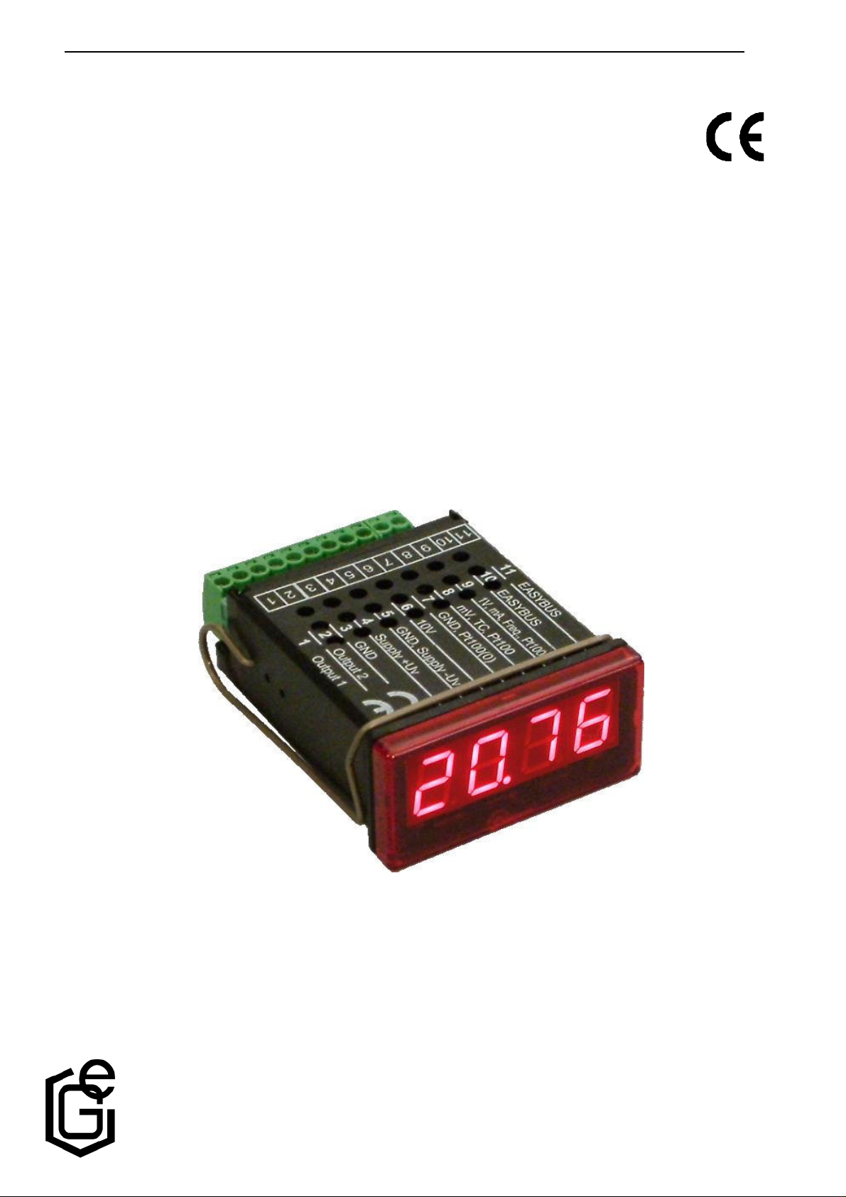
Das GIA 20 EB ist ein universell einsetzbares, mikroprozessorgesteuertes
Anzeige-, Überwachungs- und Regelgerät.
Das Gerät besitzt einen Universaleingang mit Anschlußmöglichkeiten für:
- Normsignale (0-20mA, 4-20mA, 0-50mV, 0-1V, 0-2V und 0-10V),
- Widerstandssensoren (Pt100 und Pt1000),
- Thermoelemente (Typ K, J, N, T und S)
- Frequenz (TTL und Schaltkontakt)
Ferner bietet es Funktionen wie Drehzahlmessung, Zähler, etc...
Zusätzlich stehen zwei Schaltausgänge zur Verfügung, die als 2-Punkt-
Regler, 3-Punkt-Regler, 2-Punkt-Regler mit Min-/Max-Alarm, Min-/MaxAlarm gemeinsam oder Min-/Max-Alarm getrennt konfiguriert werden können.
Der Zustand der Schaltausgänge wird mit Hilfe der 2 LED´s unterhalb der 7-Segmentanzeige angezeigt,
wobei die linke LED den Zustand des Schaltausgang 1 und die rechte LED den Schaltausgang 2 anzeigt.
Weiter besitzt das Gerät standardmäßig eine EASYBUS-Schnittstelle, die über einen Pegelwandler die Kom-
munikation mit einem übergeordneten Rechner erlaubt und das Gerät zu einem vollwertigen EASYBUS-Modul
macht.
Das GIA20EB wird geprüft und komplett kalibriert geliefert.
Damit das GIA20EB betriebsbereit ist, muß es aber noch für die jeweilige Anwendung
konfiguriert werden.
Hinweis: Um einen unzulässigen Eingangszustand und einen ungewollten oder falschen Schaltvor-
gang bei der Gerätekonfiguration zu vermeiden, wird empfohlen den Anschluß des Einganges und der Schaltausgänge erst nach der Konfiguration des Gerätes durchzuführen.
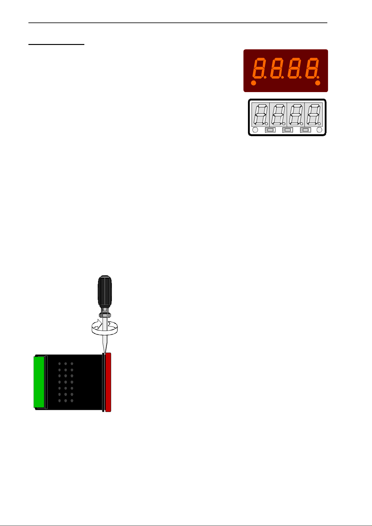
Zur Konfiguration des Gerätes gehen Sie wie folgt vor:
- rote Frontscheibe abnehmen (siehe Skizze).
- das Gerät an seine Versorgungsspannung anschließen.
(siehe Kapitel 3 'Elektrischer Anschluß)
- Versorgungsspannung einschalten und warten bis der Segmenttest
beendet ist.
- Das Gerät entsprechend Kapitel 4 'Konfiguration' an benötigtes
Eingangssignal und Ausgangsfunktion anpassen.
- Schaltverhalten des Gerätes laut den Anweisungen in Kapitel 5
'Schaltpunkte und Alarmgrenzen einstellen' einstellen.
- rote Frontscheibe wieder aufschnappen.
- Das Gerät nun komplett anschließen
(siehe Kapitel 3 'Elektrischer Anschluß‘)
E31.0.02.6B-03 Anschluß- und Bedienungsanleitung GIA 20 EB Seite 5 v. 28
3. Elektrischer Anschluß
Der Anschluß bzw. die Inbetriebnahme darf nur durch fachlich qualifizierte Personen erfolgen.
Bei fehlerhaftem Anschluß kann das Gerät zerstört werden - kein Garantieanspruch.
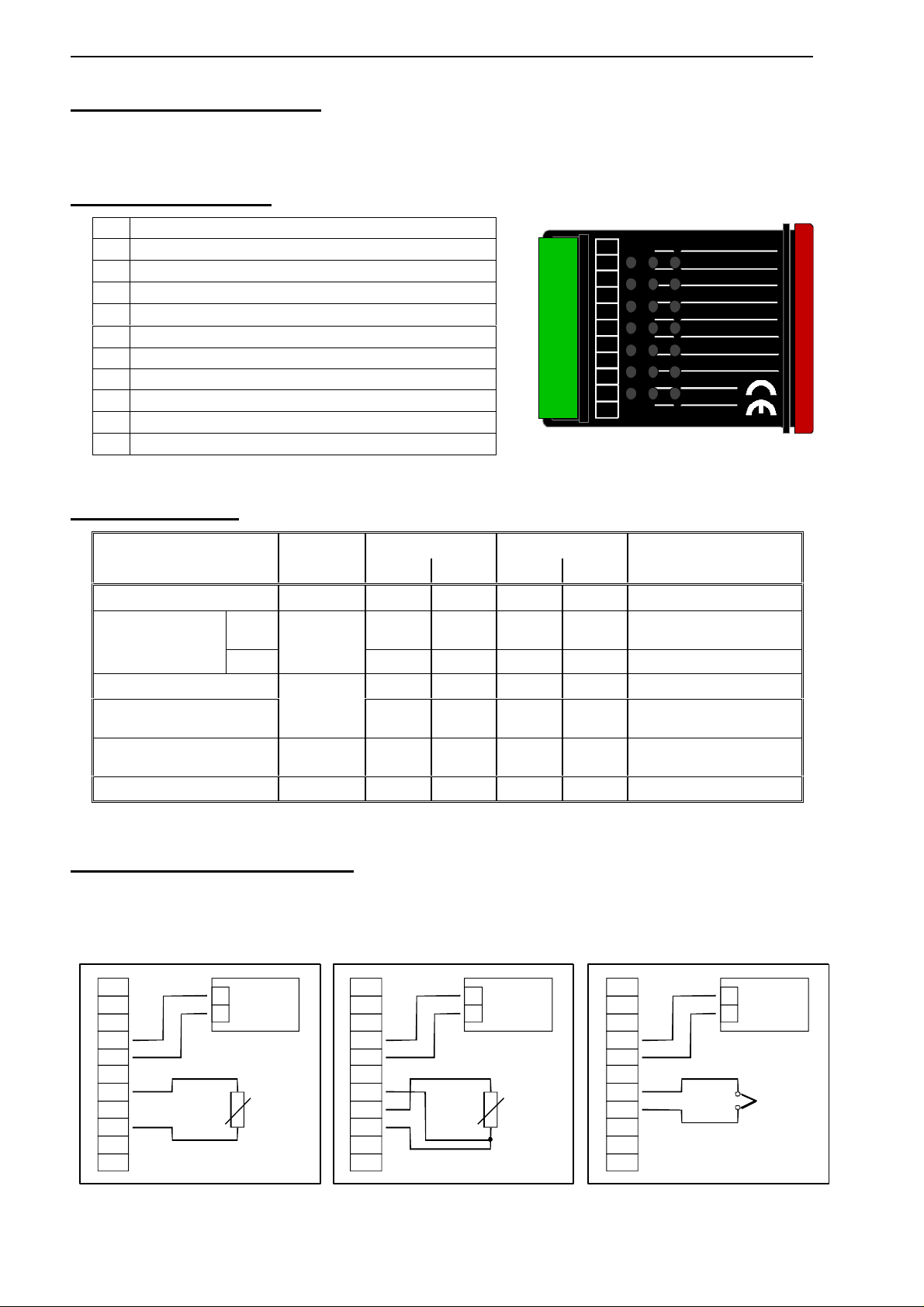
3.1. Anschlußbelegung
11 EASYBUS-Schnittstelle
10 EASYBUS-Schnittstelle
9 Eingang: 0-1V, 0-2V, mA, Frequenz, Pt100, Pt1000
8 Eingang: 0-50mV, Thermoelement, Pt100
7 Eingang: GND, Pt100, Pt1000
6 Eingang: 0-10V
5 Versorgungsspannung GND
4 Versorgungsspannung +Uv
3 Schaltausgang GND
2 Schaltausgang 2
1 Schaltausgang 1
Hinweis: die Klemmen 3, 5 und 7 sind im Gerät elektrisch verbunden.
3.2. Anschlußdaten
Betriebswerte Grenzwerte
zwischen
Anschluß
min. max. min. max.
Anmerkung
Versorgungsspannung 4 und 5 9 V 28 V 0 V 30 V
NPN
30V,
I<1A
nicht kurzschlußfest
Schaltausgang
1 und 2
PNP
1 und 3,
2 und 3
I<200mA
nicht kurzschlußfest
Eingang mA 0 mA 20 mA 0 mA 30 mA
Eingang 0-1(2)V, Freq, ...
9 und 7
0 V 3.3 V -1 V
30 V,
I<10mA
Eingang 0-50mV, TC, ... 8 und 7 0 V 3.3 V -1 V
10 V,
I<10mA
Eingang 0-10V 6 und 7 0 V 10 V -1 V 20 V
Die Grenzwerte dürfen nicht (auch nicht kurzzeitig) überschritten werden!
3.3. Eingangssignal anschließen
Beachten Sie beim Anschluß unbedingt die für den jeweiligen Eingang zulässigen Grenzwerte.
Eine Überlastung des Einganges kann zur Zerstörung des Gerätes führen.
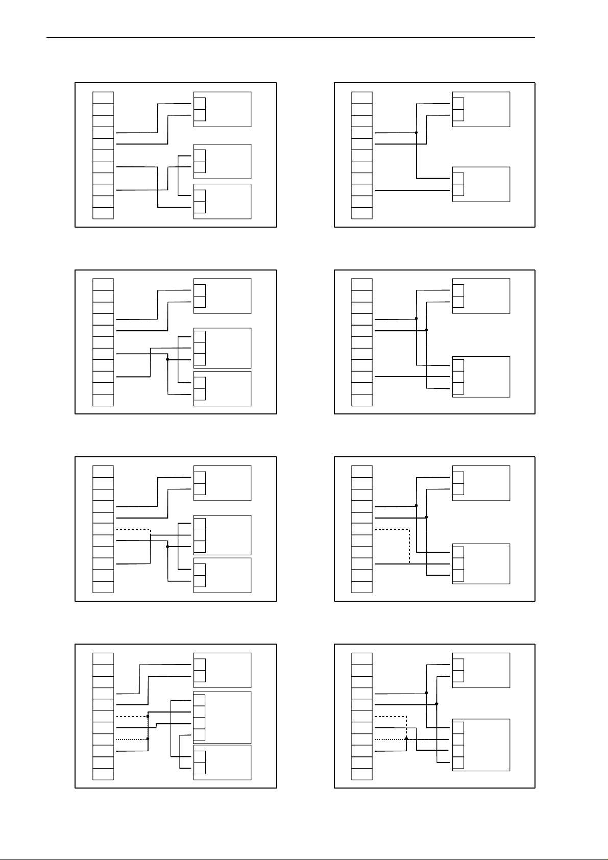
3.3.1. Anschluß eines Pt100 oder Pt1000 Temperaturfühlers bzw. Thermoelementes
Pt1000-Temperaturfühler (2-Leiter) Pt100-Temperaturfühler (3-Leiter) Thermoelement
1110 9 8 7 6 5 3 2 14
11
EASYBUS
10
EASYBUS
9
1V, mA, Freq., Pt100(0)
8
mV, TC, Pt100
7
GND, Pt100(0)
6
10V
5
GND, Supply -Uv
4
Supply +Uv
3
GND
2
Output 2
1
Output 1
4
5
7
9
+
_
9-28 VDC
Netzteil:
Pt1000
4
5
7
8
9
+
_
9-28 VDC
Netzteil:
Pt100
4
5
7
8
+
_
9-28 VDC
-
+
Netzteil:
TC
E31.0.02.6B-03 Anschluß- und Bedienungsanleitung GIA 20 EB Seite 6 v. 28
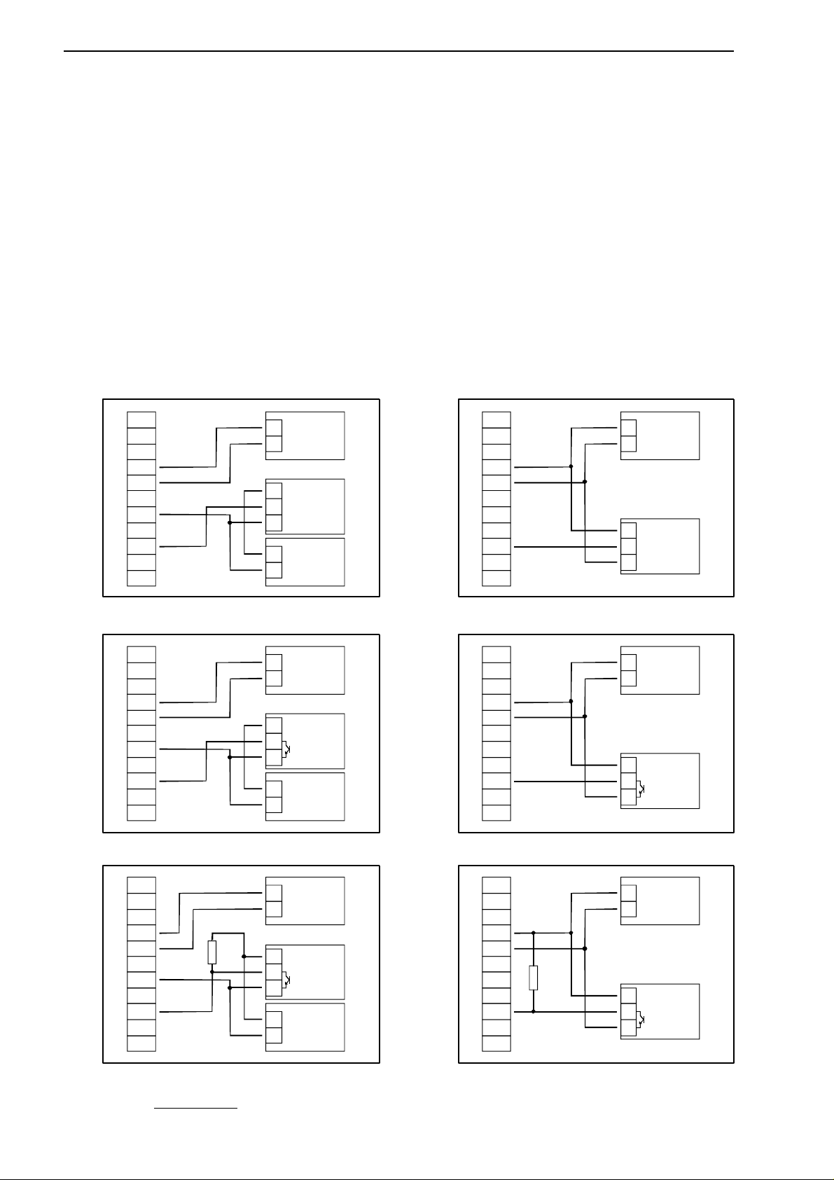
3.3.2. Anschluß eines 4-20mA Meßumformers in 2-Leiter-Technik
mit getrennter Transmitterversorgung ohne getrennte Transmitterversorgung
3.3.3. Anschluß eines 0(4)-20mA Meßumformers in 3-Leiter-Technik
mit getrennter Transmitterversorgung ohne getrennte Transmitterversorgung
3.3.4. Anschluß eines 0-1V, 0-2V oder 0-10V Meßumformers in 3-Leiter-Technik
mit getrennter Transmitterversorgung ohne getrennte Transmitterversorgung
3.3.5. Anschluß eines 0-1/2/10V bzw. 0-50mV Meßumformers in 4-Leiter-Technik
mit getrennter Transmitterversorgung ohne getrennte Transmitterversorgung
(Hinweis: Sig- und –Uv des Transmitters müssen gleiches Potential haben)
+
_
Netzteil:
9-28 VDC
4-20mA
Transmitter
+Uv
-Uv
+
_
Netzteil:
für Transmitter
4
5
7
9
+
_
Netzteil:
9-28 VDC
4-20mA
Transmitter
+Uv
-Uv
4
5
9
0(4)-20mA
Transmitter
+Uv
Sig.
-Uv
+
_
Netzteil:
9-28 VDC
+
_
Netzteil:
für Transmitter
4
5
7
9
0(4)-20mA
Transmitter
+Uv
Sig.
-Uv
+
_
Netzteil:
9-28 VDC
4
5
9
Transmitter
+Uv
Sig.
-Uv
+
_
Netzteil:
9-28 VDC
+
_
Netzteil:
für Transmitter
4
5
6
7
9
10V
1V / 2V
+
_
Netzteil:
9-28 VDC
4
5
6
9
10V
1V / 2V
Transmitter
+Uv
Sig.
-Uv
+
_
Netzteil:
9-28 VDC
+
_
Netzteil:
für Transmitter
4
5
6
7
8
9
10V
1V / 2V
Transmitter
+Uv
Sig-
-Uv
Sig+
50mV
Transmitter
+Uv
Sig-
-Uv
Sig+
+
_
Netzteil:
9-28 VDC
4
5
6
7
9
10V
1V / 2V
50mV
E31.0.02.6B-03 Anschluß- und Bedienungsanleitung GIA 20 EB Seite 7 v. 28
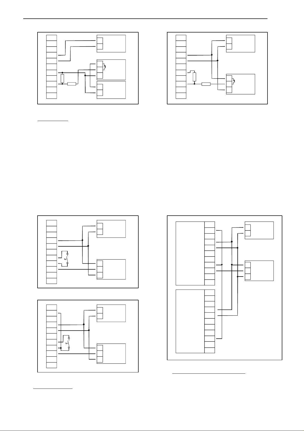
3.3.6. Anschluß eines Frequenzsignals
Bei der Frequenz- und Drehzahlmessung kann bei der Gerätekonfiguration zwischen 3 unterschiedlichen Eingangs-Signalarten ausgewählt werden. Es besteht die Möglichkeit des Anschlusses eines aktiven Signals (= TTL, ...), eines passiven Sensorsignals mit NPN (= NPN-Ausgang, Taster, Relais, ...)
oder mit PNP (= +Ub-schaltender PNP-Ausgang, High-side-Schalter, ...)
Bei der Konfigurationseinstellung „Schaltkontakt NPN“ wird im Gerät ein Pull-Up-Widerstand (~11kOhm
gegen +3.3V) zugeschaltet. Hierdurch kann bei Geräten mit NPN-Ausgang oder Schaltkontakten auf
den Anschluß eines externen Widerstandes verzichtet werden.
Bei der Konfigurationseinstellung „Schaltkontakt PNP“ wird im Gerät ein Pull-Down-Widerstand (~11kOhm
gegen GND) zugeschaltet. Hierdurch kann bei Geräten mit PNP-Ausgang auf einen externen Widerstand
verzichtet werden.
Es kann jedoch sein, daß für den Meßsignalgeber dennoch der Anschluß eines externen Widerstandes
erforderlich ist, da z.B. die Pull-Up-Spannung von 3.3V für den Geber nicht ausreicht oder im oberen
Frequenzbereich gemessen werden soll. In diesem Fall ist zu beachten, daß das Eingangssignal dann
wie ein aktives Signal zu betrachten ist und entsprechend in der Konfiguration „TTL“ auszuwählen ist.
Hinweis: beim Anschluß ist unbedingt darauf zu achten, daß die zulässige Eingangsspannung
bzw. der zulässige Eingangsstrom des Frequenzeinganges nicht überschritten wird.
Anschluß eines Gebers (mit getr. Versorgung) Anschluß eines Gebers (ohne eigene Versorgung)
mit TTL- oder PNP-Ausgang mit TTL- oder PNP-Ausgang
Anschluß eines Gebers (mit getr. Versorgung) mit NPN-Ausgang Anschluß eines Gebers (ohne eigene Versorgung) mit NPN-Ausgang
Anschluß eines Gebers (mit getr. Versorgung) mit NPN-Ausgang Anschluß eines Gebers (ohne eigene Versorgung) mit NPN-Ausgang
mit erforderlichem externen Widerstand mit erforderlichem externen Widerstand
Anschlußhinweis: Rv = 3k (bei Geberversorgung =12V) bzw. 7k (bei 24V), Gerätekonfiguration: Sens = TTL
+
_
Netzteil:
9-28 VDC
+
_
Netzteil:
für Geber
4
5
7
9
Geber
+Uv
Sig.
-Uv
+
_
Netzteil:
9-28 VDC
4
5
9
Geber
+Uv
Sig.
-Uv
+
_
Netzteil:
9-28 VDC
4
5
7
9
+
_
Netzteil:
für Geber
Rv
Geber
+Uv
Sig.
-Uv
+
_
Netzteil:
9-28 VDC
4
5
9
Rv
Geber
+Uv
Sig.
-Uv
Geber
+Uv
Sig.
-Uv
+
_
Netzteil:
9-28 VDC
+
_
Netzteil:
für Geber
4
5
7
9
+
_
Netzteil:
9-28 VDC
4
5
9
Geber
+Uv
Sig.
-Uv
E31.0.02.6B-03 Anschluß- und Bedienungsanleitung GIA 20 EB Seite 8 v. 28
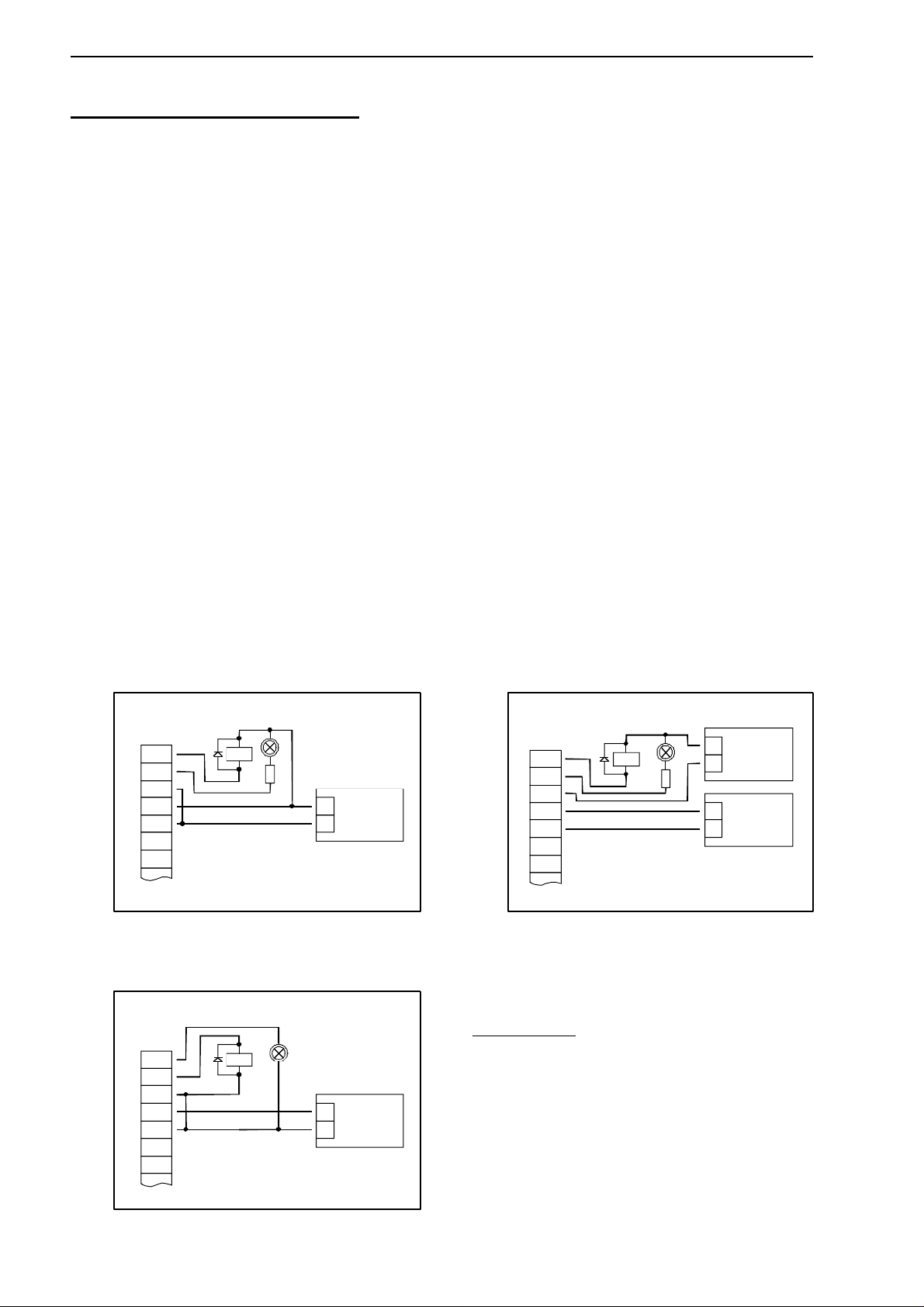
Anschluß eines Gebers (mit getr. Versorgung) mit Anschluß eines Gebers (ohne eigene Versorgung) mit
PNP-Ausgang und externer Widerstandsbeschaltung PNP-Ausgang und externer Widerstandsbeschaltung
Anschlußhinweis:Rv2 = 600r, Rv1 = 1k8 (bei Geberversorgung =12V) bzw. 4k2 (bei 24V), Gerätekonfiguration: Sens = TTL
(Rv1 dient zur Strombegrenzung und kann notfalls auch gebrückt werden. Er sollte jedoch den angegebenen Wert nicht überschreiten)
3.3.7. Anschluß eines Zählsignals
Wie bei der Frequenz- und Drehzahlmessung kann bei der Gerätekonfiguration zwischen 3 unterschiedlichen Eingangs-Signalarten ausgewählt werden.
Der Anschluß des Sensorsignals für Zählsignal erfolgt wie bei Frequenz- und Drehzahlmessung.
Verwenden Sie bitte die entsprechende Anschlußskizze aus diesem Kapitel.
Es besteht die Möglichkeit den Zählerstand jederzeit durch Verbindung der Klemme 8 mit GND (z.B.
Klemme 7) zurückzusetzen. Dies kann manuell (z.B. mit einem Taster) oder automatisch (mit einem
Schaltausgang des Gerätes) erfolgen.
Hinweis: beim Anschluß ist unbedingt darauf zu achten, daß die zulässige Eingangsspannung bzw. der
zulässige Eingangsstrom des Frequenzeingangs nicht überschritten wird
manuelles Rücksetzen mit externem Taster
automatisches Rücksetzen mit Ausgang 2 und
zusätzliches manuelles Rücksetzen mit externem Taster
Konfigurationshinweis: Ausgang 2 muß auf NPN gesetzt sein
GIA20EB kaskadierend
(Konfigurationshinweise für die GIA20EB:
Gerät 1 – Eingangssignal entsprechend Impulsgeber,
Ausgangsart von Ausgang 2 = NPN
Gerät 2 – Eingangssignal = Schaltkontakt
Rückstelltaste
+
_
Netzteil:
9-28 VDC
4
5
7
8
9
Geber
+Uv
Sig.
-Uv
+
_
Netzteil:
9-28 VDC
2
4
5
7
8
9
Gerät
Nr.1
Impuls-
geber
+Uv
Sig.
-Uv
2
4
5
7
8
9
Gerät
Nr.2
Rückstelltaste
+
_
Netzteil:
9-28 VDC
2
4
5
7
8
9
Geber
+Uv
Sig.
-Uv
+
_
Netzteil:
9-28 VDC
4
5
7
9
+
_
Netzteil:
für Geber
Geber
+Uv
Sig.
-Uv
Rv2
Rv1
+
_
Netzteil:
9-28 VDC
4
5
7
9
Geber
+Uv
Sig.
-Uv
Rv2
Rv1
E31.0.02.6B-03 Anschluß- und Bedienungsanleitung GIA 20 EB Seite 9 v. 28
3.4. Schaltausgänge anschließen
Hinweis: Um einen ungewollten oder falschen Schaltvorgang bei der Gerätekonfiguration zu
vermeiden empfehlen wird den Anschluß der Schaltausgänge erst nach der Konfiguration der gewünschten Schaltart durchzuführen.
Das Gerät besitzt 2 Schaltausgänge. Es kann in der Konfiguration des Gerätes zwischen 3 verschiedenen Schaltarten ausgewählt werden:
Low-Side: “Masse-schaltender“ NPN-Ausgang (open-collector)
Der Schaltausgang wird im aktiven Zustand (Schaltausgang ein) gegen den Minus-Pol der
Versorgungsspannung (Anschluß 3 bzw. 5) geschaltet.
High-Side: “+Ub-schaltender“ PNP-Ausgang (open-collector)
Der Schaltausgang wird im aktiven Zustand (Schaltausgang ein) gegen den Plus-Pol der
Versorgungsspannung (Anschluß 4) geschaltet.
Push-Pull: Der Schaltausgang ist im inaktiven Zustand (Schaltausgang aus) gegen den Minus-Pol der
Versorgungsspannung (Anschluß 3 bzw. 5) geschaltet und wird im aktiven Zustand
(Schaltausgang ein) gegen den Plus-Pol der Versorgung (Anschluß 4) geschaltet.
Wird ein Ausgang als Alarmausgang konfiguriert, so ist der Ausgang im Ruhezustand (kein Alarm vorhanden) 'ein'. Bei vorhandener Alarmbedingung 'öffnet' der Ausgangstransistor bzw. wechselt der PushPull-Ausgang von +Uv nach –Uv.
Bitte beachten Sie, daß die maximal zulässige Spannung, sowie der maximale Schaltstrom der
Schaltausgänge nicht (auch nicht kurzzeitig) überschritten werden darf.
Besonders beim Schalten von induktiven Lasten (z.B. Relais, Spulen usw.) ist darauf zu achten,
daß die auftretenden Spannungsspitzen durch Schutzmaßnahmen begrenzt werden.
Beim Schalten von großen kapazitiven Lasten ist es notwendig, den Einschaltstrom durch Vorschalten eines Widerstandes bzw. einer Strombegrenzung auf die zulässige Stromstärke zu begrenzen. Gleiches gilt für Glühlampen, da diese auf Grund ihres niedrigen Kaltwiderstandes
ebenfalls einen hohen Einschaltstrom haben können.
3.4.1. Anschluß bei Anschlußart Low-Side-Schalter (NPN-Ausgang, Masse schaltend)
Anschluß von Verbrauchern (Relais und Glühlampe) Anschluß von Verbrauchern (Relais und Glühlampe)
bei gemeinsamer Versorgung bei getrennter Versorgung der Verbraucher
3.4.2. Anschluß bei Anschlußart High-Side-Schalter (PNP-Ausgang, +Uv schaltend)
Anschluß von Verbrauchern (Relais und Glühlampe)
+
_
Netzteil:
9-28 VDC
+
_
Netzteil:
für Verbraucher
1
2
3
4
5
+
-
Relais
+
1
2
3
4
5
Relais
-
+
_
9-28 VDC
Netzteil:
Anschlußhinweise:
+
1
2
3
4
5
Relais
-
+
_
9-28 VDC
Netzteil:
Die Klemmen 3 und 5 sind im Gerät galvanisch verbunden.
Beim Schalten von größeren Strömen (> 50 mA) , sollten Sie
den Minus-Anschluß des Verbrauchers nicht an die Klemme 3
sondern direkt an die –Uv des Netzteiles anschließen.
Hierdurch werden mögliche Probleme durch Masseverschiebungen vermieden.

E31.0.02.6B-03 Anschluß- und Bedienungsanleitung GIA 20 EB Seite 10 v. 28
3.4.3. Anschluß bei Anschlußart Push-Pull-Ausgang
Anschluß eines Halbleiterrelais
3.5. Gemeinsamer Betrieb von mehreren Geräten
Die Ein- und Ausgänge des Gerätes sind nicht galvanisch getrennt. Werden mehrere Geräte miteinander
verdrahtet ist daher darauf zu achten, daß keine unzulässigen Potentialverschiebungen auftreten.
Insbesondere sind folgende Punkte zu berücksichtigen:
- Werden mehrere Geräte mit einer gemeinsamen Versorgungsspannung versorgt, so ist es empfehlenswert
die Meßgeber (Sensoren, Meßumformer) untereinander galvanisch zu trennen.
- Haben die Meßgeber untereinander eine galvanische Verbindung, so sollten die Geräte mit galvanisch
getrennten Versorgungsspannungen betrieben werden.
Bitte beachten Sie, daß die galvanische Verbindung der Meßgeber auch über das zu messende Medium
entstehen kann (z.B. pH-Elektrode und Leitwertelektrode in einer Flüssigkeit).
+
-
Uin
Halbleiter-
relais
+
_
Netzteil:
9-28 VDC
1
2
3
4
5

E31.0.02.6B-03 Anschluß- und Bedienungsanleitung GIA 20 EB Seite 11 v. 28
4. Konfiguration des Gerätes
Bitte beachten: Wird bei der Eingabe länger als 60 sec. keine Taste gedrückt, so wird die Konfiguration des
Gerätes abgebrochen.
Gegebenenfalls bereits getätigte Änderungen werden hierbei nicht gespeichert und gehen somit verloren!
Hinweis: Die Tasten 2 und 3 sind bei der Eingabe von Werten mit einer 'Roll-Funktion' ausgestattet. Wird die Taste kurz
gedrückt erhöht (Taste 2) bzw. erniedrigt (Taste 3) sich der Anzeigewert jeweils um 1 Digit.
Wird die Taste länger gedrückt (> 1s) beginnt der Wert auf- bzw. abwärts zu zählen, wobei die Geschwindigkeit nach kurzer Zeit erhöht wird.
Die Einstellung ist ferner mit einer ‘Überlauf-Funktion‘ ausgestattet. Wird bei der Einstellung der max. mögliche Einstellwert erreicht, so wird zum min. möglichen Einstellwert gewechselt und umgekehrt.
4.1. Eingangssignal auswählen
- Gerät in Betrieb nehmen und warten bis der Segmenttest beendet ist.
- Taste 2 für >2 Sekunden drücken (z.B. mit kleinem Schraubenzieher)
In der Anzeige erscheint “InP“ ('INPUT').
- Mit Taste 2 oder Taste 3 (mittlere bzw. rechte Taste) die gewünschte Meßart auswählen (siehe unten stehende Tabelle).
- Mit Taste 1 gewählte Meßart bestätigen. In der Anzeige erscheint wieder “InP“
Abhängig von der gewählten Meßart müssen weitere Einstellungen im entsprechenden Kapitel gemacht werden.
Meßart Eingangssignal
Als Input ein-
zustellen
weiter in Kapitel
0 – 10 V
0 – 2 V
0 – 1 V
Spannungssignal
0 – 50 mV
U 4.2
4 – 20 mAStromsignal
0 – 20 mA
I 4.2
Pt100 (0.1°C)
Pt100 (1°C)
Widerstand
Pt1000
t.rES 4.3
NiCr-Ni (Typ K)
Pt10Rh-Pt (Typ S)
NiCrSi-NiSi (Typ N)
Fe-CuNi (Typ J)
Thermoelement
Cu-CuNi (Typ T)
t.tc 4.3
TTL-SignalFrequenz
Schaltkontakt NPN, PNP
FrEq 4.4
TTL-SignalDrehzahl
Schaltkontakt NPN, PNP
rPn 4.5
TTL-SignalAufwärtszähler
Schaltkontakt NPN, PNP
Co.uP 4.6
TTL-SignalAbwärtszähler
Schaltkontakt NPN, PNP
Co.dn 4.6
Schnittstellenbetrieb serielle Schnittstelle
SEri 4.7
Bitte Beachten: Bei Veränderung der Einstellung für Meßart “InP“, Eingangssignal “SEnS“ und der
Anzeigeeinheit “Unit“ werden alle anderen Einstellungen auf Werkseinstellung zurückgesetzt. Alle anderen Konfigurationspunkte müssen daher neu eingestellt werden.
Dies betrifft auch die gemachten Einstellungen für Offset und Steigungskorrektur
sowie die Einstellung der Schaltpunkte!
Taster 1
Taster 2
Taster 3
E31.0.02.6B-03 Anschluß- und Bedienungsanleitung GIA 20 EB Seite 12 v. 28
4.2. Spannungs- und Strommessung (0-50mV, 0-1V, 0-2V, 0-10V, 0-20mA, 4-20mA)
Dieses Kapitel beschreibt die Konfiguration des Gerätes für Spannungs- und Stromsignale.
Diese Anweisung setzt voraus, daß Sie, entsprechend der Anweisung unter Kapitel 4.1. als Meßart “U“ oder
“I“ gewählt haben. In der Anzeige muß “InP“ stehen.
- Taste 1 drücken. In der Anzeige erscheint nun “SEnS“.
- Mit Taste 2 oder Taste 3 (mittlere bzw. rechte Taste) das gewünschte Eingangssignal auswählen.
Anzeige
Eingangssignal (Spannungsmes-
sung)
Anmerkung
10.00 0 – 10 V
2.00 0 – 2 V
1.00
0 – 1 V
0.050
0 – 50 mV
Anzeige
Eingangssignal
(Strommessung)
Anmerkung
4-20 4 – 20 mA
0-20
0 – 20 mA
- Mit Taste 1 gewähltes Eingangssignal bestätigen. In der Anzeige erscheint wieder “SEnS“.
- Taste 1 nochmals drücken, in der Anzeige erscheint “dP“ (Dezimalpunkt).
- Mit den Tasten 2 und 3 die gewünschte Dezimalpunktposition auswählen.
- Mit Taste 1 Dezimalpunktposition bestätigen. In der Anzeige steht wieder “dP“.
- Taste 1 nochmals drücken, in der Anzeige erscheint “di.Lo“ (Display Low = Untere Anzeigebereichsgrenze).
- Geben Sie nun mit den Tasten 2 und 3 den Anzeigewert ein, den das Gerät bei einem Eingangssignal
von 0mA, 4mA bzw. 0 Volt anzeigen soll.
- Den eingestellten Wert mit Taste 1 bestätigen. In der Anzeige steht wieder “di.Lo“.
- Taste 1 nochmals drücken, in der Anzeige erscheint “di.Hi“ (Display High = Obere Anzeigebereichsgrenze).
- Geben Sie nun mit den Tasten 2 und 3 den Anzeigewert ein, den das Gerät bei einem Eingangssignal
von 20mA, 50mV, 1 Volt, 2 Volt bzw. 10 Volt anzeigen soll.
- Den eingestellten Wert mit Taste 1 bestätigen. In der Anzeige steht wieder “di.Hi“.
- Taste 1 erneut drücken. In der Anzeige erscheint “Li“ (Limit = Meßbereichsbegrenzung).
- Mit den Tasten 2 und 3 gewünschte Meßbereichsbegrenzung wählen.
Anzeige Meßbereichsbegrenzung Anmerkung
off Deaktiviert
Überschreitung der Meßbereichsgrenzen um
ca. 10% zulässig.
on.Er aktiv, (Fehleranzeige)
Meßbereich ist genau auf das Eingangssignal
begrenzt. Bei Über-/Unterschreitung wird eine
entsprechende Fehlermeldung angezeigt.
on.rG
aktiv, (Anzeige Meßbereichsgrenze)
Meßbereich ist genau auf das Eingangssignal
begrenzt. Bei Über-/Unterschreitung wird die
Anzeigebereichsgrenze angezeigt.
[z.B. für Feuchte: bei Unter-/Überschreitung
wird weiter 0% bzw. 100% angezeigt]
Hinweis:Bei einer Überschreitung der Meßbereichsgrenzen von >10% wird unabhängig von der Limit-Einstellung
immer die entsprechende Fehlermeldung (“Err.1“ bzw. “Err.2“) angezeigt.
- Mit Taste 1 Auswahl bestätigen. In der Anzeige steht wieder “Li“.
- Taste 1 nochmals betätigen. In der Anzeige erscheint “FiLt“ (Filter = digitaler Filter).
E31.0.02.6B-03 Anschluß- und Bedienungsanleitung GIA 20 EB Seite 13 v. 28
- Mit den Tasten 2 und 3 wird der gewünschte Filterwert [in sec.] eingestellt.
Einstellbare Werte: 0.01 ... 2.00 sec.
Erklärung: bei dem digitalen Filter handelt es sich um die digitale Nachbildung eines Tiefpaßfilters.
Anwendungshinweis: bei Eingangssignal 0-50mV wird empfohlen einen Filterwert von min. 0.2 zu wählen.
- Mit Taste 1 bestätigen, in der Anzeige steht wieder “FiLt“.
Damit ist die Anpassung des Gerätes an Ihre Signalquelle abgeschlossen. Sie müssen jetzt noch die Ausgänge des Gerätes konfigurieren.
- Bei nochmaligem Drücken von Taste 1 erscheint in der Anzeige “outP“. (Output)
Es folgt nun die Konfiguration des Ausganges - folgen Sie hierzu den Anweisungen in Kapitel 4.8.
4.3. Temperaturmessung (Pt100, Pt1000 und Thermoelemente Typ J, K, N, S oder T)
Dieses Kapitel beschreibt die Konfiguration des Gerätes für Temperaturmessung mit Platin-Temperatursensoren oder Thermoelemente. Diese Anweisung setzt voraus, daß Sie, entsprechend der Anweisung unter Kapitel 4.1. als Meßart “t.res“ oder “t.tc“ gewählt haben. In der Anzeige muß “InP“ stehen.
- Taste 1 drücken. In der Anzeige erscheint nun “SEnS“.
- Mit Taste 2 oder Taste 3 (mittlere bzw. rechte Taste) das gewünschte Eingangssignal auswählen.
Anzeige
Eingangssignal
(Widerstand)
Anmerkung
Pt0.1 Pt100 (3-Leiter)
Meßbereich: -50.0 ... +200.0 °C (-58.0 ... + 392.0 °F)
Auflösung: 0.1°
Pt1 Pt100 (3-Leiter)
Meßbereich: -200 ... + 850 °C (-328 ... + 1562 °F)
Auflösung: 1°
1000
Pt1000 (2-Leiter)
Meßbereich: -200 ... + 850 °C (-328 ... + 1562 °F)
Auflösung: 1°
Anzeige
Eingangssignal
(Thermoelemente)
Anmerkung
niCr NiCr-Ni (Typ K) Meßbereich: -270 ... +1350 °C (-454 ... + 2462 °F)
S Pt10Rh-Pt (Typ S) Meßbereich: -50 ... +1750 °C (- 58 ... + 3182 °F)
n NiCrSi-NiSi (Typ N) Meßbereich: -270 ... +1300 °C (-454 ... + 2372 °F)
J Fe-CuNi (Typ J) Meßbereich: -170 ... + 950 °C (-274 ... + 1742 °F)
t Cu-CuNi (Typ T) Meßbereich: -270 ... + 400 °C (-454 ... + 752 °F)
- Mit Taste 1 gewähltes Eingangssignal bestätigen. In der Anzeige erscheint wieder “SEnS“.
- Taste 1 nochmals drücken, in der Anzeige erscheint “Unit“ (Anzeigeeinheit).
- Mit den Tasten 2 und 3 kann ausgewählt werden, ob die Temperatur in °C oder °F angezeigt werden soll.
- Mit Taste 1 die gewählte Meßeinheit bestätigen. In der Anzeige steht wieder “Unit“.
- Taste 1 nochmals betätigen. In der Anzeige erscheint “FiLt“ (Filter = digitaler Filter).
- Mit den Tasten 2 und 3 wird der gewünschte Filterwert [in sec.] eingestellt.
Einstellbare Werte: 0.01 ... 2.00 sec.
Erklärung: bei dem digitalen Filter handelt es sich um die digitale Nachbildung eines Tiefpaßfilters.
- Mit Taste 1 bestätigen, in der Anzeige steht wieder “FiLt“.
Damit ist die Anpassung des Gerätes an Ihre Signalquelle abgeschlossen. Sie müssen jetzt noch die Ausgänge des Gerätes konfigurieren.
- Bei nochmaligem Drücken von Taste 1 erscheint in der Anzeige “outP“. (Output)
Es folgt nun die Konfiguration des Ausganges - folgen Sie hierzu den Anweisungen in Kapitel 4.8.
Für die Einstellung von Offset- und Steigungskorrektur lesen Sie bitte Kapitel 6.
E31.0.02.6B-03 Anschluß- und Bedienungsanleitung GIA 20 EB Seite 14 v. 28
4.4. Frequenzmessung (TTL, Schaltkontakt)
Dieses Kapitel beschreibt die Konfiguration des Gerätes für Frequenzmessung.
Diese Anweisung setzt voraus, daß Sie, entsprechend der Anweisung unter Kapitel 4.1. als Meßart “FrEq“
gewählt haben. In der Anzeige muß “InP“ stehen.
- Taste 1 drücken. In der Anzeige erscheint nun “SEnS“.
- Mit Taste 2 oder Taste 3 (mittlere bzw. rechte Taste) das gewünschte Eingangssignal auswählen.
Anzeige Eingangssignal Anmerkung
ttL TTL-Signal
nPn
Schaltkontakt, NPN
zum direkten Anschluß eines passiven
Schaltkontaktes (z.B. Taster, Relais) bzw.
Gebers mit NPN-Ausgang.
Pull-up-Widerstand ist im Gerät integriert.
Hinweis: bei Einsatz von Tastern und Relais sind
prellfreie Taster bzw. Relais zu verwenden!
PnP
Schaltkontakt, PNP
zum direkten Anschluß eines Gebers mit
PNP-Ausgang.
Pull-down-Widerstand ist im Gerät integriert.
Hinweis:Bitte beachten Sie die Hinweise für den Anschluß eines Frequenzgebers (siehe 3.3.6)
Bei Anschluß von Schaltkontakt-Gebern mit erhöhten Frequenzbereich (= mit externer Beschaltung) ist
entsprechend der Anschlußbeschreibung das Eingangssignal TTL auszuwählen.
- Mit Taste 1 gewähltes Eingangssignal bestätigen. In der Anzeige erscheint wieder “SEnS“.
- Taste 1 nochmals drücken, in der Anzeige erscheint “Fr.Lo“ (Frequenz Low = Untere Meßfrequenzgrenze).
- Geben Sie nun mit den Tasten 2 und 3 den minimal bei der Messung auftretenden Frequenzwert ein.
- Den eingestellten Wert mit Taste 1 bestätigen. In der Anzeige steht wieder “Fr.Lo“.
- Taste 1 nochmals drücken, in der Anzeige erscheint “Fr.Hi“ (Frequenz High = obere Meßfrequenzgrenze).
- Geben Sie nun mit den Tasten 2 und 3 den maximal bei der Messung auftretenden Frequenzwert ein.
- Den eingestellten Wert mit Taste 1 bestätigen. In der Anzeige steht wieder “Fr.Hi“.
- Taste 1 nochmals drücken, in der Anzeige erscheint “dP“ (Dezimalpunkt).
- Mit den Tasten 2 und 3 die gewünschte Dezimalpunktposition auswählen.
- Mit Taste 1 Dezimalpunktposition bestätigen. In der Anzeige steht wieder “dP“.
- Taste 1 nochmals drücken, in der Anzeige erscheint “di.Lo“ (Display Low = Untere Anzeigebereichsgrenze).
- Geben Sie nun mit den Tasten 2 und 3 den Anzeigewert ein, den das Gerät bei der unteren Meßfrequenzgrenze (Einstellung von fr.Lo) anzeigen soll.
- Den eingestellten Wert mit Taste 1 bestätigen. In der Anzeige steht wieder “di.Lo“.
- Taste 1 nochmals drücken, in der Anzeige erscheint “di.Hi“ (Display High = Obere Anzeigebereichsgrenze).
- Geben Sie nun mit den Tasten 2 und 3 den Anzeigewert ein, den das Gerät bei der oberen Meßfrequenzgrenze (Einstellung von fr.Hi) anzeigen soll.
- Den eingestellten Wert mit Taste 1 bestätigen. In der Anzeige steht wieder “di.Hi“.
- Taste 1 erneut drücken. In der Anzeige erscheint “Li“ (Limit = Meßbereichsbegrenzung).
- Mit den Tasten 2 und 3 gewünschte Meßbereichsbegrenzung wählen.
Anzeige Meßbereichsbegrenzung Anmerkung
off Deaktiviert
Überschreitung der Meßfrequenzgrenzen bis
zum max. Meßbereich ist zulässig.
on.Er Aktiv, (Fehleranzeige)
Meßbereich ist genau auf die Meßfrequenzgrenzen begrenzt. Bei Über-/Unterschreitung
wird eine entspr. Fehlermeldung angezeigt.

E31.0.02.6B-03 Anschluß- und Bedienungsanleitung GIA 20 EB Seite 15 v. 28
on.rG
aktiv, (Anzeige Meßbereichsgrenze)
Meßbereich ist genau auf die Meßfrequenzgrenzen begrenzt. Bei Über-/Unterschreitung
wird die Anzeigebereichsgrenze angezeigt.
[z.B. für Feuchte: bei Unter-/Überschreitung
wird weiter 0% bzw. 100% angezeigt]
Hinweis:Bei einer Überschreitung der max. Meßbereichsgrenzen (10kHz) wird unabhängig von der Limit-
Einstellung immer die entsprechende Fehlermeldung (“Err.1“) angezeigt.
- Mit Taste 1 Auswahl bestätigen. In der Anzeige steht wieder “Li“.
- Taste 1 nochmals betätigen. In der Anzeige erscheint “FiLt“ (Filter = digitaler Filter).
- Mit den Tasten 2 und 3 wird der gewünschte Filterwert [in sec.] eingestellt.
Einstellbare Werte: 0.01 ... 2.00 sec.
Erklärung: bei dem digitalen Filter handelt es sich um die digitale Nachbildung eines Tiefpaßfilters.
- Mit Taste 1 bestätigen, in der Anzeige steht wieder “FiLt“.
Damit ist die Anpassung des Gerätes an Ihre Signalquelle abgeschlossen. Sie müssen jetzt noch die Ausgänge des Gerätes konfigurieren.
- Bei nochmaligem Drücken von Taste 1 erscheint in der Anzeige “outP“. (Output)
Es folgt nun die Konfiguration des Ausganges - folgen Sie hierzu den Anweisungen in Kapitel 4.8.
4.5. Drehzahlmessung (TTL, Schaltkontakt)
Dieses Kapitel beschreibt die Konfiguration des Gerätes für Drehzahlmessung.
Diese Anweisung setzt voraus, daß Sie, entsprechend der Anweisung unter Kapitel 4.1. als Meßart “rPn“
gewählt haben. In der Anzeige muß “InP“ stehen.
- Taste 1 drücken. In der Anzeige erscheint nun “SEnS“.
- Mit Taste 2 oder Taste 3 (mittlere bzw. rechte Taste) das gewünschte Eingangssignal auswählen.
Anzeige Eingangssignal Anmerkung
ttL TTL-Signal
nPn
Schaltkontakt, NPN
zum direkten Anschluß eines passiven
Schaltkontaktes (z.B. Taster, Relais) bzw.
Gebers mit NPN-Ausgang.
Pull-up-Widerstand ist im Gerät integriert.
Hinweis: bei Einsatz von Tastern und Relais sind
prellfreie Taster bzw. Relais zu verwenden!
PnP
Schaltkontakt, PNP
zum direkten Anschluß eines Gebers mit
PNP-Ausgang.
Pull-down-Widerstand ist im Gerät integriert.
Hinweis:Bitte beachten Sie die Hinweise für den Anschluß eines Frequenzgebers (siehe 3.3.6)
Bei Anschluß von Schaltkontakt-Gebern mit erhöhten Frequenzbereich (= mit externer Beschaltung) ist
entsprechend der Anschlußbeschreibung das Eingangssignal TTL auszuwählen.
- Mit Taste 1 gewähltes Eingangssignal bestätigen. In der Anzeige erscheint wieder “SEnS“.
- Taste 1 nochmals drücken, in der Anzeige erscheint “diu“ (Divisor = Vorteiler).
- Geben Sie nun mit den Tasten 2 und 3 den gewünschten Vorteiler ein.
Der Vorteiler ist auf die Anzahl der Impulse, die Ihr Geber pro Umdrehung liefert, einzustellen.
- Den eingestellten Wert mit Taste 1 bestätigen. In der Anzeige steht wieder “diu“.
- Taste 1 nochmals drücken, in der Anzeige erscheint “dP“ (Dezimalpunkt).
- Geben Sie nun mit den Tasten 2 und 3 die gewünschte Position des Dezimalpunktes ein.
Mit der Position des Dezimalpunktes kann die Auflösung der Drehzahlmessung beeinflußt werden.
Je weiter der Dezimalpunkt nach links verschoben wird, desto feiner ist die Auflösung. Beachten Sie jedoch, daß hierdurch auch der max. darstellbare Umdrehungswert reduziert wird.
Beispiel: Ihr Motor läuft derzeit mit ca. 50 Umdrehungen/min.
Bei keinem Dezimalpunkt ist die mögliche Anzeige 49 – 50 – 51, der max. Anzeigewert ist 9999 U/min.
Bei Dezimalpunkt --.-- ist die Anzeige 49.99 – 50.00 – 50.01, der max. Anzeigewert beträgt 99.99 U/min.

E31.0.02.6B-03 Anschluß- und Bedienungsanleitung GIA 20 EB Seite 16 v. 28
- Den eingestellten Wert mit Taste 1 bestätigen. In der Anzeige steht wieder “dP“.
Damit ist die Anpassung des Gerätes an Ihre Signalquelle abgeschlossen. Sie müssen jetzt noch die Ausgänge des Gerätes konfigurieren.
- Bei nochmaligem Drücken von Taste 1 erscheint in der Anzeige “outP“. (Output)
Es folgt nun die Konfiguration des Ausganges - folgen Sie hierzu den Anweisungen in Kapitel 4.8.
4.6. Auf-/Abwärtszähler (TTL, Schaltkontakt)
Der Aufwärtszähler beginnt bei 0 und zählt entsprechend seiner Einstellung nach oben.
Beim Abwärtszähler wird mit dem Zählvorgang bei der eingestellten oberen Anzeigebereichsgrenze begonnen und entsprechend der Einstellung nach unten gezählt.
Der Zählerstand kann jederzeit durch Verbinden der Klemme 8 mit GND (z.B. Klemme 7) zurückgesetzt
werden. Der Zählvorgang beginnt dann wieder von vorne sobald die Verbindung wieder aufgehoben wird.
Besonderheit: Der aktuelle Zählerstand bleibt bei Stromausfall erhalten. Nach Neustart zählt das Gerät ab
diesem Zählerstand weiter.
Dieses Kapitel beschreibt die Konfiguration des Gerätes für Zählfunktion.
Diese Anweisung setzt voraus, daß Sie, entsprechend der Anweisung unter Kapitel 4.1. als Meßart “Co.up“
bzw. “Co.dn“ gewählt haben. In der Anzeige muß “InP“ stehen.
- Taste 1 drücken. In der Anzeige erscheint nun “SEnS“.
- Mit Taste 2 oder Taste 3 (mittlere bzw. rechte Taste) das gewünschte Eingangssignal auswählen.
Anzeige Eingangssignal Anmerkung
ttL TTL-Signal
nPn
Schaltkontakt, NPN
zum direkten Anschluß eines passiven
Schaltkontaktes (z.B. Taster, Relais) bzw.
Gebers mit NPN-Ausgang.
Pull-up-Widerstand ist im Gerät integriert.
Hinweis: bei Einsatz von Tastern und Relais sind
prellfreie Taster bzw. Relais zu verwenden!
PnP
Schaltkontakt, PNP
zum direkten Anschluß eines Gebers mit
PNP-Ausgang.
Pull-down-Widerstand ist im Gerät integriert.
Hinweis:Bitte beachten Sie die Hinweise für den Anschluß eines Frequenzgebers (siehe 3.3.7)
Bei Anschluß von Schaltkontakt-Gebern mit erhöhten Frequenzbereich (= mit externer Beschaltung) ist
entsprechend der Anschlußbeschreibung das Eingangssignal TTL auszuwählen.
- Mit Taste 1 gewähltes Eingangssignal bestätigen. In der Anzeige erscheint wieder “SEnS“.
- Taste 1 drücken. In der Anzeige erscheint nun “EdGE“ (Signalflanke).
- Mit Taste 2 oder Taste 3 (mittlere bzw. rechte Taste) die gewünschte Signalflanke auswählen.
Anzeige Signalflanke Anmerkung
PoS positiv
Die Übernahme des Zählimpulses erfolgt mit
der positiven (steigenden) Flanke
nEG
negativ
Die Übernahme des Zählimpulses erfolgt mit
der negativen (fallenden) Flanke
- Mit Taste 1 gewählte Signalflanke bestätigen. In der Anzeige erscheint wieder “EdGE“.
- Taste 1 nochmals drücken, in der Anzeige erscheint “diu“ (Divisor = Vorteiler).
E31.0.02.6B-03 Anschluß- und Bedienungsanleitung GIA 20 EB Seite 17 v. 28
- Geben Sie nun mit den Tasten 2 und 3 den gewünschten Vorteiler ein.
Die am Eingang des Gerätes ankommenden Impulse werden durch den Vorteiler geteilt, bevor sie zur
Auswertung an das Gerät gelangen.
Hierdurch ist z.B. eine einfache Anpassung des Gerätes an einen Durchflußgeber oder eine Vorskalierung für große Zählerwerte möglich.
Beispiel 1: Ihr Durchflußgeber liefert 165 Impulse je Liter. Durch die Eingabe eines Vorteilerwertes von
165 gelangt jeder 165-igste Impuls (somit 1 Impuls je Liter) zur Weiterverarbeitung.
Beispiel 2: Ihr Impulsgeber liefert während des Meßvorgangs insgesamt ca. 5 000 000 Impulse. (Dies
überschreitet jedoch den Meßbereich des Gerätes!)
Durch die Eingabe eines Vorteilers von 1000 gelangt jeder tausendste Impulse zur Weiterverarbeitung –
mit somit 5000 Werten ist der Meßbereich des Gerätes noch nicht überschritten.
- Den eingestellten Wert mit Taste 1 bestätigen. In der Anzeige steht wieder “diu“.
- Taste 1 nochmals drücken, in der Anzeige erscheint “Co.Hi“ (Counter High = Obere Zählbereichsgrenze).
- Geben Sie nun mit den Tasten 2 und 3 die max. Impulszahl (nach Vorteiler) für den Zählvorgang ein.
Beispiel: Ihr Durchflußgeber liefert 1800 Impulse je Liter, Sie haben als Vorteiler 100 eingestellt und Sie
erwarten während der Messung einen max. Durchfluß von 300 Liter.
Durch die Eingabe eines Vorteilerwertes von 100 erhalten Sie 18 Impulse je Liter. Bei der max. Durchflußmenge von 300 Liter ergibt sich eine max. Impulszahl von 18 * 300 = 5400.
- Den eingestellten Wert mit Taste 1 bestätigen. In der Anzeige steht wieder “Co.Hi“.
- Taste 1 nochmals drücken, in der Anzeige erscheint “dP“ (Dezimalpunkt).
- Mit den Tasten 2 und 3 die gewünschte Dezimalpunktposition für die Anzeige auswählen.
- Mit Taste 1 Dezimalpunktposition bestätigen. In der Anzeige steht wieder “dP“.
- Taste 1 nochmals drücken, in der Anzeige erscheint “di.Hi“ (Display High = Obere Anzeigebereichsgrenze).
- Geben Sie nun mit den Tasten 2 und 3 den Anzeigewert ein, den das Gerät bei der max. Impulszahl
(Einstellung von co.Hi) anzeigen soll.
Beispiel: Ihr Durchflußgeber liefert 1800 Impulse je Liter und Sie erwarten während der Messung einen
max. Durchfluß von 300 Liter. Sie haben als Vorteiler 100 und als Zählbereichsgrenze 5400 eingestellt.
Die Anzeige soll in einer Auflösung von 0.1 Liter erfolgen:
Es ist somit der Dezimalpunkt auf die Position ---.- zu stellen und als Anzeigegrenze 300.0 einzustellen.
- Den eingestellten Wert mit Taste 1 bestätigen. In der Anzeige steht wieder “di.Hi“.
- Taste 1 erneut drücken. In der Anzeige erscheint “Li“ (Limit = Meßbereichsbegrenzung).
- Mit den Tasten 2 und 3 gewünschte Meßbereichsbegrenzung (Zählbereichsbegrenzung) wählen.
Anzeige Meßbereichsbegrenzung Anmerkung
off Deaktiviert
Überschreitung der Zählbereichsgrenze bis
zum max. Meßbereich ist zulässig.
on.Er aktiv, (Fehleranzeige)
Meßbereich ist genau auf die eingestellte
Zählbereichsgrenze begrenzt.
Bei Über-/Unterschreitung wird eine entspr.
Fehlermeldung angezeigt.
on.rG
aktiv, (Anzeige Meßbereichsgrenze)
Meßbereich ist genau auf die eingestellte
Zählbereichsgrenze begrenzt.
Bei Über-/Unterschreitung wird die obere
Zählbereichsgrenze bzw. 0 angezeigt.
Hinweis:Die untere Zählbereichsgrenze (bei Abwärtszähler) ist fest auf 0 gesetzt.
- Mit Taste 1 Auswahl bestätigen. In der Anzeige steht wieder “Li“.
Damit ist die Anpassung des Gerätes an Ihre Signalquelle abgeschlossen. Sie müssen jetzt noch die Ausgänge des Gerätes konfigurieren.
- Bei nochmaligem Drücken von Taste 1 erscheint in der Anzeige “outP“. (Output)
Es folgt nun die Konfiguration des Ausganges - folgen Sie hierzu den Anweisungen in Kapitel 4.8.

E31.0.02.6B-03 Anschluß- und Bedienungsanleitung GIA 20 EB Seite 18 v. 28
4.7. Schnittstellenbetrieb
Im Betriebsmodus “Schnittstellenbetrieb“ führt das Gerät keine selbständige Messung durch.
Der Anzeigewert des Gerätes wird dem Gerät über die Schnittstelle gesendet.
Die Reglerfunktion bzw. Alarmüberwachung des Anzeigewertes steht weiterhin zu Verfügung.
Die EASYBUS-Adresse des Gerätes für die Kommunikation kann am Gerät oder mit einer EASYBUS-Software
(z.B. EbxKonfig) eingestellt werden. Bitte beachten Sie, daß bei einer Systeminitialisierung in einem
EASYBUS-System die Geräteadresse automatisch neu zugewiesen wird.
Dieses Kapitel beschreibt die Konfiguration des Gerätes als EASYBUS-Anzeige.
Diese Anweisung setzt voraus, daß Sie, entsprechend der Anweisung unter Kapitel 4.1. als Meßart “SEri“
gewählt haben. In der Anzeige muß “InP“ stehen.
- Taste 1 nochmals drücken, in der Anzeige erscheint “Adr“ (Adresse).
- Mit den Tasten 2 und 3 die gewünschte Geräteadresse [0 ... 239] auswählen.
- Mit Taste 1 Geräteadresse bestätigen. In der Anzeige steht wieder “Adr“.
Eine weitere Anpassung des Gerätes ist nicht erforderlich. Sie müssen jetzt noch die Ausgänge des Gerätes
konfigurieren.
- Bei nochmaligem Drücken von Taste 1 erscheint in der Anzeige “outP“. (Output)
Es folgt nun die Konfiguration des Ausganges - folgen Sie hierzu den Anweisungen in Kapitel 4.8.
4.8. Ausgangsfunktion auswählen
- Nach der Konfiguration des Einganges (Kapitel 4.2 – 4.7) ist nun die Ausgangsfunktion auszuwählen.
In der Anzeige steht nun “outP“. (Output)
- Mit Taste 2 oder Taste 3 (mittlere bzw. rechte Taste) die gewünschte Ausgangsfunktion auswählen.
Funktion
Beschreibung
Ausgang 1 Ausgang 2
Als Output
einzustellen
weiter in Kapitel
Kein Ausgang,
Gerät ist nur Anzeige
--- --- no --
2-Punkt-Regler digitaler
2-Punkt-Regler
--- 2P 5.1
3-Punkt-Regler
digitaler
2-Punkt-Regler
digitaler
2-Punkt-Regler
3P 5.1
2-Punkt-Regler mit
Min-/Max-Alarm
digitaler
2-Punkt-Regler
Min-/Max-Alarm 2P.AL 5.2
Min-/Max-Alarm,
gemeinsam
--- Min-/Max-Alarm AL.F1 5.3
Min-/Max-Alarm,
getrennt
Max-Alarm Min-Alarm AL.F2 5.3
- Mit Taste 1 gewählte Ausgangsfunktion bestätigen. In der Anzeige erscheint wieder “outP“
Die folgend beschriebenen Einstellungen sind abhängig von der gewählten Ausgangsfunktion.
Bei der Einstellung kann es deshalb vorkommen, daß bei der von Ihnen gewählten Ausgangsfunktion ein
oder mehrere Punkte nicht vorhanden sind.
- Taste 1 nochmals drücken, in der Anzeige erscheint “1.dEL“ (Verzögerung von Ausgang 1).
- Mit den Tasten 2 und 3 den gewünschten Wert für die Schaltverzögerung für Ausgang 1 einstellen.
Bemerkung: Der eingestellte Wert entspricht der Schaltverzögerung in Sekunden.
- Mit Taste 1 eingestellte Schaltverzögerung bestätigen. In der Anzeige steht wieder “1.dEL“.
- Taste 1 nochmals drücken, in der Anzeige erscheint “1.out“ (Ausgangsart von Ausgang 1).
- Mit Taste 2 oder Taste 3 (mittlere bzw. rechte Taste) die gewünschte Ausgangsart auswählen.

E31.0.02.6B-03 Anschluß- und Bedienungsanleitung GIA 20 EB Seite 19 v. 28
Anzeige Ausgangsart Anmerkung
nPn
Low-Side
NPN, open collector, GND schaltend
PnP
High-Side
PNP, open collector, +Ub schaltend
Pu.Pu
Push-Pull
- Den eingestellten Wert mit Taste 1 bestätigen. In der Anzeige steht wieder “ 1.out“.
- Taste 1 nochmals drücken, in der Anzeige erscheint “1.Err“ (Vorzugslage von Ausgang 1).
- Mit Taste 2 oder Taste 3 (mittlere bzw. rechte Taste) den gewünschten Ausgangszustand im Fehlerfall
auswählen.
Anzeige
Vorzugslage des Schaltaus-
ganges
Anmerkung
off im Fehlerfall inaktiv
Low-/High-Side-Schalter ist im Fehlerfall geöffnet,
Push-Pull-Ausgang ist im Fehlerfall auf Low
on
im Fehlerfall aktiv
Low-/High-Side-Schalter ist im Fehlerfall geschlo ssen,
Push-Pull-Ausgang ist im Fehlerfall auf High
- Den eingestellten Zustand mit Taste 1 bestätigen. In der Anzeige steht wieder “ 1.Err“.
- Bei Ausführung 3-Punkt-Regler erfolgt nun analog zur Einstellung von Ausgang 1 die Einstellung für den
Ausgang 2. Die angezeigten Menüpunkte sind:
“2.dEL“ (Verzögerung Ausgang 2), “2.out“ (Ausgangsart Ausgang 2), “2.Err“ (Vorzugslage Ausgang 2).
- Taste 1 nochmals drücken (erfolgt nur bei Ausgangsausführung mit Min-/Max-Alarm),
in der Anzeige erscheint “A.out“ (Ausgangsart des Alarmausganges).
- Mit Taste 2 oder Taste 3 (mittlere bzw. rechte Taste) die gewünschte Ausgangsart auswählen.
Anzeige Ausgangsart Anmerkung
nPn
Low-Side
NPN, open collector, GND schaltend
Schaltausgang ist ohne Alarmbedingung geschlossen (mit GND verbunden) und wird im
Alarmfall geöffnet.
PnP
High-Side
PNP, open collector, +Ub schaltend
Schaltausgang ist ohne Alarmbedingung geschlossen (liefert somit eine Spannung) und
wird im Alarmfall geöffnet.
Pu.Pu
Push-Pull
Schaltausgang ist ohne Alarmbedingung auf
High und wird im Alarmfall auf Low geschaltet.
Bitte beachten: Die Schaltausgänge sind als Alarmausgang invertiert!
Das heißt, solange keine Alarmbedingung vorliegt ist der Schaltausgang aktiv.
Tritt eine Alarmbedingung auf so wird der Schaltausgang inaktiv
Bemerkung: Bei der Ausgangsfunktion „Min-/Max-Alarm, getrennt“ gilt die Einstellung der Ausgangsart
für beide Alarmausgänge.
- Den eingestellten Wert mit Taste 1 bestätigen. In der Anzeige steht wieder “ A.out“.
Abhängig von der gewählten Ausgangsfunktion erfolgt nun noch die Einstellung der Schalt- bzw. Alarmpunkte. Hierzu müssen weitere Einstellungen entsprechend dem Kapitel „Schaltpunkte bzw. Alarmgrenzen
einstellen“ gemacht werden.
Hinweis: Die Einstellung der Schalt- und Alarmpunkte kann zu einem späteren Zeitpunkt in einem geson-
derten Menü nachgeholt werden. (siehe Kapitel 5)

E31.0.02.6B-03 Anschluß- und Bedienungsanleitung GIA 20 EB Seite 20 v. 28
5. Schaltpunkte bzw. Alarmgrenzen einstellen
Bitte beachten: Wird bei der Eingabe länger als 60 sec. keine Taste gedrückt, so wird die Schaltpunkteinstellung des Gerätes abgebrochen.
Gegebenenfalls gemachte Änderungen werden hierbei nicht gespeichert und gehen somit verloren!
Bitte beachten: Bei Veränderung der Konfigurations-Einstellung für “InP“, “SEnS“ bzw. “Unit“ werden bereits
getätigte Einstellungen für Schaltpunkte bzw. Alarmgrenzen zurückgesetzt!
Hinweis: Die Tasten 2 und 3 sind bei der Eingabe von Werten mit einer 'Roll-Funktion' ausgestattet. Wird die Taste kurz
gedrückt erhöht (Taste 2) bzw. erniedrigt (Taste 3) sich der Anzeigewert jeweils um 1 Digit.
Wird die Taste länger gedrückt (> 1s) beginnt der Wert auf- bzw. abwärts zu zählen, wobei die Geschwindigkeit nach kurzer Zeit erhöht wird.
Die Einstellung ist ferner mit einer ‘Überlauf-Funktion‘ ausgestattet. Wird bei der Einstellung der max. mögliche Einstellwert erreicht, so wird zum min. möglichen Einstellwert gewechselt und umgekehrt.
- Der Aufruf des Menüs für die Einstellung der Schalt-/Alarmpunkte erfolgt
durch Drücken auf Taste 1 für >2 Sekunden.
- Abhängig von der in der Konfiguration unter „Output“ gewählten Einstellung
erfolgt eine unterschiedliche Anzeige. Wechseln Sie hierzu in das entsprechend Kapitel.
Funktion
Beschreibung
Ausgang 1 Ausgang 2
Als Output
eingestellt
weiter in Kapitel
Kein Ausgang,
Gerät ist nur Anzeige
--- --- no
Aufruf nicht
möglich !
2-Punkt-Regler digitaler
2-Punkt-Regler
--- 2P 5.1
3-Punkt-Regler digitaler
2-Punkt-Regler
digitaler
2-Punkt-Regler
3P 5.1
2-Punkt-Regler mit
Min-/Max-Alarm
digitaler
2-Punkt-Regler
Min-/Max-Alarm 2P.AL 5.2
Min-/Max-Alarm, gemeinsam
--- Min-/Max-Alarm AL.F1 5.3
Min-/Max-Alarm,
getrennt
Max-Alarm Min-Alarm AL.F2 5.3
5.1. 2-Punkt-Regler, 3-Punkt-Regler
Dieses Kapitel beschreibt die Einstellung der Schaltpunkte bei Verwendung des Gerätes als 2-Punkt- bzw.
3-Punkt-Reglers.
Diese Anweisung setzt voraus, daß Sie, entsprechend der Anweisung unter Kapitel 4.8, die Ausgangsfunktion “2P“ oder “3P“ gewählt haben.
- Taste 1 drücken (sofern nicht schon geschehen).
In der Anzeige erscheint nun “1.on“. (Einschaltpunkt von Ausgang 1)
- Mit den Tasten 2 und 3 den gewünschten Wert einstellen, bei dem der Ausgang 1 einschalten soll.
- Mit Taste 1 eingestellten Schaltpunkt bestätigen. In der Anzeige steht wieder “1.on“.
- Taste 1 drücken. In der Anzeige erscheint nun “1.off“. (Ausschaltpunkt von Ausgang 1)
- Mit den Tasten 2 und 3 den gewünschten Wert einstellen, bei dem der Ausgang 1 ausschalten soll.
- Mit Taste 1 eingestellten Schaltpunkt bestätigen. In der Anzeige steht wieder “1.off“.
Beispiel: Sie haben eine Heizplatte und möchten diese auf eine Temperatur von 120°C, mit einer Hystere-
se von +2°C regeln.
Hierfür ist für den Einschaltpunkt “1.on“ = 120°C und den Ausschaltpunkt “1.off“ = 122°C einzustellen. => Bei einer Temperatur unter 120°C schaltet das Gerät ein, bei 122°C schaltet es aus.
Bemerkung: Je nach Trägheit Ihrer Heizplatte ist ein Überschwingen der Temperatur möglich.
Taster 1
Taster 2
Taster 3

E31.0.02.6B-03 Anschluß- und Bedienungsanleitung GIA 20 EB Seite 21 v. 28
Wenn Sie als Ausgangsverhalten '2-Punkt-Regler' gewählt haben, ist damit die Schaltpunkteinstellung des
Gerätes abgeschlossen. Drücken Sie nochmals die Taste 3 um zur Anzeige des Meßwertes umzuschalten.
Wenn Sie '3-Punkt-Regler' gewählt haben, fahren Sie bitte wie folgt fort:
- Taste 1 drücken. In der Anzeige erscheint nun “2.on“. (Einschaltpunkt von Ausgang 2)
- Mit den Tasten 2 und 3 den gewünschten Wert einstellen, bei dem der Ausgang 2 einschalten soll.
- Mit Taste 1 eingestellten Schaltpunkt bestätigen. In der Anzeige steht wieder “2.on“.
- Taste 1 drücken. In der Anzeige erscheint nun “2.off“. (Ausschaltpunkt von Ausgang 2)
- Mit den Tasten 2 und 3 den gewünschten Wert einstellen, bei dem der Ausgang 2 ausschalten soll.
- Mit Taste 1 eingestellten Schaltpunkt bestätigen. In der Anzeige steht wieder “2.off“.
Damit ist die Schaltpunkteinstellung des Gerätes abgeschlossen. Drücken Sie die Taste 3 um zur Anzeige
des Meßwertes umzuschalten.
5.2. 2-Punkt-Regler mit Alarm
Dieses Kapitel beschreibt die Einstellung der Schalt- und Alarmpunkte bei Verwendung des Gerätes als
2-Punkt-Regler mit Min-/Max-Alarm. Diese Anweisung setzt voraus, daß Sie, entsprechend der Anweisung
unter Kapitel 4.8, die Ausgangsfunktion “2P.AL“ gewählt haben.
- Taste 1 drücken (sofern nicht schon geschehen). In der Anzeige erscheint nun “1.on“. (Einschaltpunkt von Ausgang 1)
- Mit den Tasten 2 und 3 den gewünschten Wert einstellen, bei dem der Ausgang 1 einschalten soll.
- Mit Taste 1 eingestellten Schaltpunkt bestätigen. In der Anzeige steht wieder “1.on“.
- Taste 1 drücken. In der Anzeige erscheint nun “1.off“. (Ausschaltpunkt von Ausgang 1)
- Mit den Tasten 2 und 3 den gewünschten Wert einstellen, bei dem der Ausgang 1 ausschalten soll.
- Mit Taste 1 eingestellten Schaltpunkt bestätigen. In der Anzeige steht wieder “1.off“.
Beispiel: Sie haben einen Kühlraum und möchten diesen auf eine Temperatur zwischen -20°C und -22°C
regeln.
Hierfür ist für den Einschaltpunkt “1.on“ = -20°C und den Ausschaltpunkt “1.off“ = -22°C einzustellen. => Bei einer Temperatur über -20°C schaltet das Gerät ein, bei -22°C schaltet es aus.
Bemerkung: Je nach Trägheit Ihres Kühlkreislaufes ist ein Überschwingen der Temperatur möglich.
- Taste 1 drücken. In der Anzeige erscheint nun “AL.Hi“. (Max-Alarmpunkt)
- Mit den Tasten 2 und 3 den gewünschten Wert einstellen, ab dem Max-Alarm ausgelöst werden soll.
- Mit Taste 1 eingestellten Alarmpunkt bestätigen. In der Anzeige steht wieder “AL.Hi“.
- Taste 1 drücken. In der Anzeige erscheint nun “AL.Lo“. (Min-Alarmpunkt)
- Mit den Tasten 2 und 3 den gewünschten Wert einstellen, bei dem Min-Alarm ausgelöst werden soll.
- Mit Taste 1 eingestellten Alarmpunkt bestätigen. In der Anzeige steht wieder “AL.Lo“.
- Taste 1 drücken. In der Anzeige erscheint nun “A.dEL“. (Alarmverzögerung)
- Mit den Tasten 2 und 3 den gewünschten Wert für die Alarmverzögerung einstellen.
Bemerkung: Der eingestellte Wert entspricht der Alarmverzögerung in Sekunden.
Der Alarmfall muß für die als Alarmverzögerung eingestellte Zeit anstehen, damit die
Alarmmeldung ausgelöst wird.
- Mit Taste 1 eingestellte Alarmverzögerung bestätigen. In der Anzeige steht wieder “A.dEL“.
Beispiel: Sie möchten die Temperatur im oben beschriebenen Kühlraum zusätzlich auf Temperatur von
-15°C und -30°C alarmüberwachen.
Hierfür ist für den Max-Alarm “AL.Hi“ = -15°C und den Min-Alarm “AL.Lo“ = -30°C einzustellen.
=> Steigt die Temperatur über -15°C bzw. sinkt sie unter -30°C ab, so löst das Gerät nach der
eingestellten Alarmverzögerung den Alarm aus.
Bitte beachten Sie, daß der Alarmausgang invertiert ist. Das heißt der Schaltausgang ist bei keinem Alarm
aktiv.
Damit ist die Schaltpunkt- und Alarmeinstellung des Gerätes abgeschlossen. Drücken Sie die Taste 3 um zur
Anzeige des Meßwertes umzuschalten.

E31.0.02.6B-03 Anschluß- und Bedienungsanleitung GIA 20 EB Seite 22 v. 28
5.3. Min-/Max-Alarm (getrennt oder gemeinsam)
Dieses Kapitel beschreibt die Einstellung der Alarmpunkte bei Verwendung des Gerätes zur Min-/MaxwertÜberwachung. Diese Anweisung setzt voraus, daß Sie, entsprechend der Anweisung unter Kapitel 4.8, die
Ausgangsfunktion “AL.F1“ oder “AL.F2“ gewählt haben.
- Taste 1 drücken (sofern nicht schon geschehen). In der Anzeige erscheint nun “AL.Hi“. (Max-Alarmpunkt)
- Mit den Tasten 2 und 3 den gewünschten Wert einstellen, ab dem Max-Alarm ausgelöst werden soll.
- Mit Taste 1 eingestellten Alarmpunkt bestätigen. In der Anzeige steht wieder “AL.Hi“.
- Taste 1 drücken. In der Anzeige erscheint nun “AL.Lo“. (Min-Alarmpunkt)
- Mit den Tasten 2 und 3 den gewünschten Wert einstellen, bei dem Min-Alarm ausgelöst werden soll.
- Mit Taste 1 eingestellten Alarmpunkt bestätigen. In der Anzeige steht wieder “AL.Lo“.
- Taste 1 drücken. In der Anzeige erscheint nun “A.dEL“. (Alarmverzögerung)
- Mit den Tasten 2 und 3 den gewünschten Wert für die Alarmverzögerung einstellen.
Bemerkung: Der eingestellte Wert entspricht der Alarmverzögerung in Sekunden.
Der Alarmfall muß für die als Alarmverzögerung eingestellte Zeit anstehen, damit die
Alarmmeldung ausgelöst wird.
- Mit Taste 1 eingestellte Alarmverzögerung bestätigen. In der Anzeige steht wieder “A.dEL“.
Beispiel: Sie möchten die Temperatur in einem Gewächshaus auf 15°C und 50°C alarmüberwachen.
Hierfür ist für den Max-Alarm “AL.Hi“ = 50°C und den Min-Alarm “AL.Lo“ = 15°C einzustellen.
=> Steigt die Temperatur über 50°C bzw. sinkt sie unter 15°C ab, so löst das Gerät nach der eingestellten Alarmverzögerung den Alarm aus.
Bitte beachten Sie, daß der Alarmausgang invertiert ist. Das heißt der Schaltausgang ist bei keinem Alarm
aktiv.
Damit ist die Alarmeinstellung des Gerätes abgeschlossen. Drücken Sie die Taste 3 um zur Anzeige des
Meßwertes umzuschalten.

E31.0.02.6B-03 Anschluß- und Bedienungsanleitung GIA 20 EB Seite 23 v. 28
6. Offset- und Steigungskorrektur
Die Offset- und Steigungskorrektur dient zum Ausgleich von Sensortoleranzen bzw. zur Feinjustierung von
Abweichungen Ihres Meßumformers bzw. Signalgebers.
Bitte beachten: Wird bei der Eingabe länger als 60 sec. keine Taste gedrückt, so wird die Offset-/ Steigungskorrektur des Gerätes abgebrochen.
Gegebenenfalls gemachte Änderungen werden hierbei nicht gespeichert und gehen somit verloren!
Bitte beachten: Bei Veränderung der Konfigurations-Einstellung für “InP“, “SEnS“ bzw. “Unit“ werden bereits
getätigte Einstellungen für Offset- und Steigungskorrektur zurückgesetzt!
Hinweis: Die Tasten 2 und 3 sind bei der Eingabe von Werten mit einer 'Roll-Funktion' ausgestattet. Wird die Taste kurz
gedrückt erhöht (Taste 2) bzw. erniedrigt (Taste 3) sich der Anzeigewert jeweils um 1 Digit.
Wird die Taste länger gedrückt (> 1s) beginnt der Wert auf- bzw. abwärts zu zählen, wobei die Geschwindigkeit nach kurzer Zeit erhöht wird.
Die Einstellung ist ferner mit einer ‘Überlauf-Funktion‘ ausgestattet. Wird bei der Einstellung der max. mögliche Einstellwert erreicht, so wird zum min. möglichen Einstellwert gewechselt und umgekehrt.
- Gerät in Betrieb nehmen und warten bis der Segmenttest beendet ist.
- Taste 3 für >2 Sekunden drücken (z.B. mit kleinem Schraubenzieher)
In der Anzeige erscheint “OFFS“ (Offset = Nullpunktverschiebung).
- Mit den Tasten 2 und 3 den gewünschten Offset-Wert einstellen.
Die Eingabe des Offset erfolgt in Digit bzw. °C/°F.
Der eingestellte Offset-Wert wird von dem gemessenen Wert abgezogen. (genaue Berechnung siehe bei Scale)
- Mit Taste 1 eingestellten Schaltpunkt bestätigen. In der Anzeige steht wieder “OFFS“.
- Taste 1 drücken. In der Anzeige erscheint nun “SCAL“. (Scale = Steigung)
- Mit den Tasten 2 und 3 den gewünschten Steigungskorrekturwert einstellen.
Die Eingabe der Steigungskorrektur erfolgt in %. Der Anzeigewert wird nach folgender Formel berechnet:
Anzeige = (gemessener Wert – Offset) * (1 + Steigungskorrektur [% / 100] )
Beispiel:Die Einstellung ist 2.00 => Steigung ist um 2.00% erhöht => Steigung = 102%. Bei einem gemessenen
Wert von 1000 (ohne Steigungskorrektur) würde das Gerät nun 1020 anzeigen.
- Mit Taste 1 eingestellten Steigungskorrekturwert bestätigen. In der Anzeige steht wieder “SCAL“.
Damit ist die Einstellung von Offset- und Steigungskorrektur des Gerätes abgeschlossen. Drücken Sie die
Taste 3 um zur Anzeige des Meßwertes umzuschalten.
Beispiele für Offset- und Steigungskorrektur:
Beispiel 1: Anschluß eines Pt1000-Fühlers (mit Offsetfehler durch die Kabellänge des Sensorkabels)
Die Geräteanzeige ohne Offset und Steigungskorrektur ist wie folgt: bei 0°C = 2°C, bei 100°C = 102°C
Hieraus errechnet sich: Nullpunkt: 2
Steigung: 102 – 2 = 100 (Abweichung = 0)
Folglich sind einzustellen: Offset = 2 (= Nullpunktabweichung)
Scale = 0.00
Beispiel 2: Anschluß eines 4-20mA-Druckmeßumformers
Die Geräteanzeige ohne Offset und Steigungskorrektur ist wie folgt: bei 0 bar = 0.08, bei 20 bar = 20.02
Hieraus errechnet sich: Nullpunkt: 0.08
Steigung: 20.02 – 0.08 = 19.94
Abweichung: 0.06 (= Soll-Steigung – Ist-Steigung = 20.00 - 19.94)
Folglich sind einzustellen: Offset = 0.08 (= Nullpunktabweichung)
Scale = 0.30 (= Abweichung / Ist-Steigung = 0.06 / 19.94 = 0.0030 = 0.30% )
Beispiel 3: Anschluß eines Durchflußmeßgebers
Die Geräteanzeige ohne Offset und Steigungskorrektur ist wie folgt: bei 0 l/min. = 0.00, bei 16 l/min. = 16.17
Hieraus errechnet sich: Nullpunkt: 0.00
Steigung: 16.17 – 0.00 = 16.17
Abweichung: -0.17 (= Soll-Steigung – Ist-Steigung = 16.00 - 16.17)
Folglich sind einzustellen: Offset = 0.00
Scale = -1.05 (= -Abweichung / Ist-Steigung = -0.17 / 16.17 = -0.0105 = -1.05% )
Taster 1
Taster 2
Taster 3

E31.0.02.6B-03 Anschluß- und Bedienungsanleitung GIA 20 EB Seite 24 v. 28
7. Min-/Max-Wertspeicher
Das Gerät besitzt eine Min-/Max-Wertspeicher. Darin wird der tiefste und der höchste Betriebswert gespeichert.
Abruf des Min.-Wertes: Taste 3 kurz drücken es wird kurz “Lo“ angezeigt, anschließend
wird für ca. 2 sec. der Min-Wert angezeigt.
Abruf des Max.-Wertes: Taste 2 kurz drücken es wird kurz “Hi“ angezeigt, anschließend
wird für ca. 2 sec. der Max-Wert angezeigt.
Löschen des Min-/Max-Wertes: Taste 2 u. 3 gleichzeitig für 2 sec. drücken es wird in der Anzeige kurz “CLr“ ange-
zeigt, der Min-/Max-Wert wird auf den aktuellen Anzeigewert zurückgesetzt.
8. Serielle Schnittstelle
Das Gerät besitzt eine EASYBUS-Schnittstelle. Das Gerät kann als vollwertiges EASYBUS-Modul betrieben werden.
Die serielle Schnittstelle des Gerätes ermöglicht die Kommunikation des Gerätes mit einem übergeordneten
Rechner. Die Datenabfrage und Übertragung erfolgt im Master/Slave-Betrieb, d.h. das Gerät sendet nur
Daten auf Anforderung. Jedes Gerät besitzt eine ID-Nummer, so daß eine eindeutige Identifikation möglich
ist. Mit der entsprechenden Software (z.B. EBxKonfig – kostenlos im Internet erhältlich) kann dem Gerät eine
Geräteadresse zugeordnet werden.
Benötigtes Zubehör für den Schnittstellenbetrieb:
- Pegelwandler EASYBUS ó PC: z.B. EBW1, EBW64, EB2000MC
- Software für die Kommunikation mit dem Gerät
EBS9M: 9-Kanal-Software zum Anzeigen des Meßwertes
EASYCONTROL: Universal Mehrkanal-Software zur Echtzeitaufzeichnung und -darstellung von Meßdaten
eines Gerätes im ACCESS®-Datenbankformat
EASYBUS-DLL: EASYBUS-Entwicklerpaket zur Entwicklung eigener Software, dieses enthält eine
universelle Windows®-Funktionsbibliothek mit Dokumentation und Programmbeispielen. Die DLL kann von allen gängigen Programmiersprachen eingebunden werden.
9. Fehlercodes
Erkennt das Gerät unzulässige Betriebszustände, wird ein entsprechender Fehlercode angezeigt.
Folgende Fehlercodes sind definiert:
Err.1: Meßbereich überschritten
Diese Fehlermeldung signalisiert, daß der Meßbereich des Gerätes überschritten wird.
Mögliche Fehlerursache: - Eingangssignal zu groß
- Fühlerbruch (bei Pt100 und Pt1000)
- Fühlerschluß (bei 0(4)-20mA)
- Zählerüberlauf
Abhilfe: - Die Fehlermeldung wird zurückgesetzt, sobald das Eingangssignal
wieder innerhalb der zugelassenen Grenzen liegt.
- Sensor, Meßumformer bzw. Frequenzgeber überprüfen.
- Gerätekonfiguration überprüfen (z.B. Eingangssignal).
- Zähler rücksetzen.
Err.2: Meßbereich unterschritten
Diese Fehlermeldung signalisiert, daß der Meßbereich des Gerätes unterschritten wird.
Mögliche Fehlerursache: - Eingangssignal zu klein bzw. negativ
- Strom kleiner 4mA
- Fühlerschluß (bei Pt100 und Pt1000)
- Fühlerbruch (bei 4-20mA)
- Zählerunterlauf

E31.0.02.6B-03 Anschluß- und Bedienungsanleitung GIA 20 EB Seite 25 v. 28
Abhilfe: - Die Fehlermeldung wird zurückgesetzt, sobald das Eingangssignal
wieder innerhalb der zugelassenen Grenzen liegt.
- Sensor, Meßumformer bzw. Frequenzgeber überprüfen.
- Gerätekonfiguration überprüfen (z.B. Eingangssignal).
- Zähler rücksetzen.
Err.3: Anzeigebereich überschritten
Diese Fehlermeldung signalisiert, daß der max. mögliche Anzeigebereich von 9999 Digit des
Gerätes überschritten wird.
Mögliche Fehlerursache: - Skalierung fehlerhaft
- Zählerüberlauf
Abhilfe: - Die Fehlermeldung wird zurückgesetzt, sobald der Anzeigewert
wieder < 9999 ist.
- Zähler rücksetzen.
- Bei häufigem Auftreten sollte ggf. überlegt werden ob der durch die
Skalierung gewählte Anzeigebereich nicht zu groß gewählt wurde und
entsprechend reduziert werden sollte (z.B. Faktor 10)
Err.4: Anzeigebereich unterschritten
Diese Fehlermeldung signalisiert, daß der min. mögliche Anzeigebereich von -1999 Digit des
Gerätes unterschritten wird.
Mögliche Fehlerursache: - Skalierung fehlerhaft
- Zählerunterlauf
Abhilfe: - Die Fehlermeldung wird zurückgesetzt, sobald der Anzeigewert
wieder innerhalb der zugelassenen Grenzen liegt.
- Zähler rücksetzen.
- Bei häufigem Auftreten sollte ggf. überlegt werden ob der durch die
Skalierung gewählte Anzeigebereich nicht zu groß gewählt wurde und
entsprechend reduziert werden sollte (z.B. Faktor 10)
Err.7: Systemfehler
Das Gerät hat eine integrierte Eigendiagnosefunktion, die ständig wesentliche Teile des Gerätes
kontrolliert. Erkennt die Diagnosefunktion einen Defekt, wird die Fehlermeldung Err.7 angezeigt.
Mögliche Fehlerursache: - zulässige Betriebstemperatur über- bzw. unterschritten
- Gerät defekt
Abhilfe: - Betriebstemperatur einhalten
- Gerät austauschen.
Err.9: Sensor defekt
Das Gerät hat eine integrierte Diagnosefunktion für den angeschlossen Fühler oder Geber.
Erkennt die Diagnosefunktion einen Defekt, wird die Fehlermeldung Err.9 angezeigt.
Mögliche Fehlerursache: - Fühlerbruch bzw. Fühlerkurzschluß bei Pt100 oder Pt1000
- Fühlerbruch bei Thermoelementen
Abhilfe: - Sensor kontrollieren und ggf. austauschen
Er.11: Wert konnte nicht berechnet werden
Diese Fehlermeldung signalisiert, daß eine für die Berechnung des Anzeigewertes nötige
Meßgröße fehlerhaft oder außerhalb des zulässigen Bereiches ist.
Mögliche Fehlerursache: - Skalierung fehlerhaft
Abhilfe: - Einstellung und Eingangssignal prüfen

E31.0.02.6B-03 Anschluß- und Bedienungsanleitung GIA 20 EB Seite 26 v. 28
10. Technische Daten
Max. Anschlußdaten:
Betriebswerte Grenzwerte
zwischen
Anschluß
min. max. min. max.
Anmerkung
Versorgungsspannung 4 und 5 9 V 28 V 0 V 30 V
NPN
30V,
I<1A
nicht kurzschlußfest
Schaltausgang
1 und 2
PNP
1 und 3,
2 und 3
I<200mA nicht kurzschlußfest
Eingang mA 9 und 7 0 mA 20 mA 0 mA 30 mA
Eingang 0-1(2)V, Freq, ... 9 und 7 0 V 3.3 V -1 V
30 V,
I<10mA
Eingang 0-50mV, TC, ... 8 und 7 0 V 3.3 V -1 V
10 V,
I<10mA
Eingang 0-10V 6 und 7 0 V 10 V -1 V 20 V
Die Grenzwerte dürfen nicht (auch nicht kurzzeitig) überschritten werden!
Meßeingänge: Universaleingang für
Meßart Eingangssignal Meßbereich Auflösung Bemerkung
0 – 10 V 0 ... 10 V Ri > 300 kOhm
0 – 2 V 0 ... 2 V Ri > 10 kOhm
0 – 1 V 0 ... 1 V Ri > 10 kOhm
Spannungssignal
0 – 50 mV 0 ... 50 mV Ri > 10 kOhm
4 – 20 mA 4 ... 20 mA Ri = ~ 125 OhmStromsignal
0 – 20 mA 0 ... 20 mA Ri = ~ 125 Ohm
Pt100 (0.1°C)
-50.0 ... +200.0 °C
(bzw. –58 ... +392 °F)
0.1 °C bzw. °F
3-Leiter-Anschluß
max. zul. Leitungswiderstand: 20 Ohm
Pt100 (1°C)
-200 ... +850 °C
(bzw. -328 ... +1562 °F)
1 °C bzw. °F
3-Leiter-Anschluß
max. zul. Leitungswiderstand: 20 Ohm
Widerstand
Pt1000
-200 ... +850 °C
(bzw. -328 ... +1562 °F)
1 °C bzw. °F 2-Leiter-Anschluß
NiCr-Ni (Typ K)
-270 ... +1350 °C
(bzw. -454 ... +2462 °F)
1 °C bzw. °F
Pt10Rh-Pt (Typ S)
-50 ... +1750 °C
(bzw. -58 ... +3182 °F)
1 °C bzw. °F
NiCrSi-NiSi (Typ N)
-270 ... +1300 °C
(bzw. -454 ... +2372 °F)
1 °C bzw. °F
Fe-CuNi (Typ J)
-170 ... +950 °C
(bzw. -274 ... +1742 °F)
1 °C bzw. °F
Thermoelement
Cu-CuNi (Typ T)
-270 ... +400 °C
(bzw. -454 ... +752 °F)
1 °C bzw. °F
TTL-Signal 0 Hz ... 10 kHz 0.001 Hz
Schaltkontakt NPN 0 Hz ... 3 kHz 0.001 Hz
interner Pull-Up-Widerstand (~11 kOhm
gegen +3.3V) wird zugeschaltet.
Frequenz
Schaltkontakt PNP 0 Hz ... 1 kHz 0.001 Hz
interner Pull-Down-Widerstand (~11
kOhm gegen GND) wird zugeschaltet.
Drehzahl
TTL-Signal,
Schaltkontakt NPN, PNP
0 ... 9999 U/min 0.001 U/min
zuschaltbarer Vorteiler (1-1000),
Pulsfrequenz: max. 600000 Imp./min. *
Abwärtszähler,
Aufwärtszähler
TTL-Signal,
Schaltkontakt NPN, PNP
0 ... 9999
mit Vorteiler: 9 999 000
zuschaltbarer Vorteiler (1-1000)
Pulsfrequenz: max. 10000 Imp./sec. *
* = bei Schaltkontakt entsprechend Frequenzeingang geringere Werte

E31.0.02.6B-03 Anschluß- und Bedienungsanleitung GIA 20 EB Seite 27 v. 28
Anzeigebereich: (für Spannung-, Strom-, Frequenzmessung)
-1999 ... 9999 Digit, Anfangs-, Endwert und Dezimalpunktposition frei wählbar
empfohlene Spanne: < 2000 Digit
Genauigkeit: (bei Nenntemperatur)
Normsignal: < 0.2% FS ±1Digit (bei 0 – 50mV: < 0.3% FS ±1Digit)
Widerstandsthermometer:< 0.5% FS ±1Digit
Thermoelemente: < 0.3% FS ±1Digit (bei Type S: < 0.5% FS ±1Digit)
Frequenz: < 0.2% FS ±1Digit
Vergleichstellengenauigkeit: ±1°C ±1Digit (bei Nenntemperatur)
Temperaturdrift: < 0.01% FS / K (bei Pt100 – 0.1°C: < 0.015% FS / K)
Meßrate: ca. 100 Messungen / sec. (bei Normsignal) bzw.
ca. 4 Messungen / sec. (bei Temperaturmessung) bzw.
ca. 4 Messungen / sec. (bei Frequenz, rpm mit f > 4 Hz) bzw. entsprechend f (bei f < 4 Hz)
Ausgänge: 2 Schaltausgänge, nicht galv. getrennt,
Ausgangsart: wählbar: Low-Side, High-Side oder Push-Pull
Anschlußdaten: Low-Side: 28V/1A; High-Side: Ub/200mA
Reaktionszeit: < 20 msec. bei Normsignal
< 0.3 sec. bei Temperatur, Frequenz (f > 4 Hz)
Ausgangsfunktionen: 2-Punkt, 3-Punkt, 2-Punkt mit Alarm, Min-/Max-Alarm gemeinsam oder getrennt.
Schaltpunkte: frei wählbar
Anzeige: ca. 10 mm hohe, 4-stellige rote LED-Anzeige
Bedienung: mittels 3 Taster, zugänglich nach Abnahme der Frontblende oder über Schnittstelle.
Schnittstelle: EASYBUS-Schnittstelle, galv. getrennt
Spannungsversorgung: 9 bis 28 V DC
Stromverbrauch: max. 30 mA (ohne Schaltausgang)
Nenntemperatur: 25°C
Arbeitstemperatur: -20 bis +50°C
Relative Feuchte: 0 bis 80% r.F. (nicht betauend)
Lagertemperatur: -30 bis +70°C
Gehäuse: glasfaserverstärktes Noryl, Sichtscheibe Polycarbonat
Abmessung: 24 x 48 mm (Frontrahmenmaß).
Einbautiefe: ca. 65 mm (incl. Schraub-/Steckklemmen)
Panelbefestigung: mit VA-Federklammer.
Mögliche Paneldicken: von 1 bis ca. 10 mm.
Panelausschnitt: 21.7+0.5 x 45+0.5 mm (H x B)
Elektroanschluß: über Schraub-/Steckklemme: 2-pol. für Schnittstelle und 9-pol. für übrige Anschlüsse.
Leiterquerschnitte von 0.14 bis 1.5 mm².
Schutzklasse: frontseitig IP54, mit optionellen O-Ringen IP65
Elektromagnetische Verträglichkeit (EMV): EN61326 +A1 +A2 (Anhang A, Klasse B),
zusätzlicher Fehler: < 1% FS
Bei Anschluß von langen Leitungen sind entsprechend geeignete externe Maßnah-
men gegen Stoßspannungen vorzusehen.

E31.0.02.6C-03 Manual for connection and operation of the GIA 20 EB page 1 of 28
Manual for connection and operation of
GIA 20 EB
Version 2.0
GREISINGER electronic GmbH
D - 93128 Regenstauf, Hans-Sachs-Straße 26
Phone: 0049 9402 / 9383-0, Fax: 0049 9402 / 9383-33, e-mail: info@greisinger.de

E31.0.02.6C-03 Manual for connection and operation of the GIA 20 EB page 2 of 28
I N D E X
1. SAFETY REGULATIONS.................................................................................................................................................3
2. INTRODUCTION................................................................................................................................................................4
3. ELECTRIC CONNECTION..............................................................................................................................................5
3.1. Terminal assignment....................................................................................................................................................... 5
3.2. Connection data............................................................................................................................................................... 5
3.3. Connecting an input signal.............................................................................................................................................5
3.3.1. Connecting a Pt100 or Pt1000 RTD probe or a thermocouple probe...................................................................5
3.3.2. Connecting a 4-20mA transmitter in 2-wire-technology.......................................................................................6
3.3.3. Connecting a 0(4)-20mA transmitter in 3-wire-technology..................................................................................6
3.3.4. Connecting a 0-1V, 0-2V or 0-10V transmitter in 3-wire-technology.................................................................6
3.3.5. Connecting a 0-1/2/10V or 0-50mV transmitter in 4-wire-technology................................................................6
3.3.6. Connecting a frequency- or rotation-signal............................................................................................................7
3.3.7. Connecting a counter signal....................................................................................................................................8
3.4. Connecting switching outputs........................................................................................................................................9
3.4.1. Connection with configured low-side-switching output (NPN output, switching to GND)...............................9
3.3.2. Connection with configured high-side-switching output (PNP output, switching to +Uv)................................ 9
3.4.3. Connection with configured push-pull-switching output....................................................................................10
3.5. Commen wiring of several GIA20EB .........................................................................................................................10
4. CONFIGURATION OF THE DEVICE.........................................................................................................................11
4.1. Selecting an input signal type.......................................................................................................................................11
4.2. Measuring voltage and current (0-50mV, 0-1V, 0-2V, 0-10V, 0-20mA, 4-20mA) .................................................12
4.3. Measuring temperature (Pt100, Pt1000 RTD probes and thermocouple type J, K, N, S or T) .........................................13
4.4. Measuring of frequency (TTL, switching-contact)....................................................................................................14
4.5. Measuring of rotation speed (TTL, switching-contact).............................................................................................15
4.6. Up-/Downwards counter (TTL, switching-contact)...................................................................................................16
4.7. Interface mode...............................................................................................................................................................18
4.8. Selection of the output function...................................................................................................................................18
5. SWITCHPOINTS RESP. ALARM-BOUNDARIES....................................................................................................20
5.1. 2-point-controller, 3-point-controller ..........................................................................................................................20
5.2. 2-point-controller with alarm function........................................................................................................................ 21
5.3. Minimum/maximum-alarm (individual or common) ................................................................................................ 22
6. OFFSET- AND SLOPE-ADJUSTMENT.......................................................................................................................23
7. MIN-/MAX-VALUE STORAGE.....................................................................................................................................24
8. SERIAL INTERFACE......................................................................................................................................................24
9. ERROR CODES.................................................................................................................................................................24
10. SPECIFICATION............................................................................................................................................................26

E31.0.02.6C-03 Manual for connection and operation of the GIA 20 EB page 3 of 28
1. Safety regulations
This device was designed and tested considering the Safety regulations for electronic measuring devices.
Faultless operation and reliability in operation of the measuring device can only be assured if the General
Safety Measures and the devices specific safety regulation mentioned in this users manual are considered.
1. Faultless operation and reliability in operation of the measuring device can only be assured if the device
is used within the climatic conditions specified in the chapter “Specifications“
2. Always disconnect the device from its supply before opening it. Take care that nobody can touch any of
the unit‘s contacts after installing the device.
3. Standard regulations for operation and safety for electrical, light and heavy current equipment have to be
observed, with particular attention paid to the national safety regulations (e.g. VDE 0100).
4. When connecting the device to other devices (e.g. the PC) the interconnection has to be designed most
thoroughly, as internal connections in third-party devices (e.g. connection of ground with protective earth)
may lead to undesired voltage potentials.
5. The device must be switched off and must be marked against using again, in case of obvious malfunc-
tions of the device which are e.g.:
- visible damage.
- no prescripted working of the device.
- storing the device under inappropriate conditions for longer time.
When not sure, the device should be sent to the manufacturer for repairing or servicing.
ATTENTION: When running electric devices, parts of them will always be electrically
live. Unless the warnings are observed serious personal injuries or damage to property may result. Skilled personnel only should be allowed to work with this device. For
trouble-free and safe operation of the device please ensure professional transport,
storage, installation and connection as well as proper operation and maintenance.
SKILLED PERSONNEL
Are persons familiar with installation, connection, commissioning and operation of the product and have
professional qualification relating to their job.
For example:
• Training or instruction resp. qualifications to switch on or off, isolate, ground and mark electric circuits and
devices or systems.
• Training or instruction according to the state.
• First-aid training.
ATTENTION:
Do NOT use this product as safety or emergency stopping device, or in any other application where failure of the product could result in personal injury or material damage.
Failure to comply with these instructions could result in death or serious injury and
material damage.

E31.0.02.6C-03 Manual for connection and operation of the GIA 20 EB page 4 of 28
2. Introduction
The GIA20EB is a microprocessor controlled displaying, monitoring and
controlling device.
The device is supporting one universal interface for the connection of:
- Standard transmitter signals (0-20mA, 4-20mA, 0-50mV, 0-1V,
0-2V and 0-10V )
- RTD (for Pt100 and Pt1000),
- Thermocouple probes (type K, J, N, T and S)
- Frequency (TTL and switching contact)
As well as rotation measuring, counting, etc. ...
The device features two switching outputs, which can be configured as
2-point-controller, 3-point-controller, 2-point-controller with min./max. alarm,
common or individual min./max. alarm.
The state of the switching outputs is displayed with two LED’s beneath the
front 4-digit LED-display.
The left LED displays the state of the 1st output, the right LED displays the state of the 2nd output.
Furthermore the device supports one EASYBUS-interface for communicating with a host computer that makes
the device to a full functions EASYBUS-module.
When leaving our factory the GIA20EB has been subjected to various inspection tests and is completely
calibrated.
Before the GIA20EB can be used, it has to be configured for the customer’s application.
Hint: In order to avoid undefined input states and unwanted or wrong switching processes, we sug-
gest to connect the device’s switching outputs after You have configured the device properly.
For configuring the GIA20EB please proceed as follows:
- Disassemble the red front plate (see sketch).
- Connect the device to its supply
(see chapter 3 ‘Electric connection‘).
- Switch on the supply voltage and wait until the device completed its
built-in segment test .
- Adjust the device to the input signal required. Follow the instructions
in chapter 4 ‘Input configuration‘
- Follow the instructions given in chapter 5 ‘Output and alarm
configuration‘ to configure the outputs of the GIA20EB.
- Reassemble the red front plate.
- Connect the device properly (see chapter 3 'Electric connection‘)

E31.0.02.6C-03 Manual for connection and operation of the GIA 20 EB page 5 of 28
3. Electric connection
Wiring and commissioning of the device must be carried out by skilled personnel only.
In case of wrong wiring the GIA20EB may be destroyed. We can not assume any warranty in case of
wrong wiring of the device.
3.1. Terminal assignment
11 EASYBUS-Interface
10 EASYBUS-Interface
9 Input: 0-1V, 0-2V, mA, frequency, Pt100, Pt1000
8 Input: 0-50mV, thermocouples, Pt100
7 Input: GND, Pt100, Pt1000
6 Input: 0-10V
5 Supply voltage: GND
4 Supply voltage: +Uv
3 Switching output: GND
2 Switching output: 2
1 Switching output: 1
Hint: The contacts 3, 5 and 7 are connected internally.
3.2. Connection data
typical limitations
Between
terminals
min. max. min. max.
notes
Supply voltage 4 and 5 9 V 28 V 0 V 30 V
NPN
30V,
I<1A
Not short circuit protected
Switching output
1 and 2
PNP
1 and 3,
2 and 3
I<200mA
Not short circuit protected
Input mA 0 mA 20 mA 0 mA 30 mA
Input 0-1(2)V, Freq., ...
9 and 7
0 V 3.3 V -1 V
30 V,
I<10mA
Input 0-50mV, TC, ... 8 and 7 0 V 3.3 V -1 V
10 V,
I<10mA
Input 0-10V 6 and 7 0 V 10 V -1 V 20 V
These limits must not be exceeded (not even for a short time) !
3.3. Connecting an input signal
Please take care not to exceed the limitations of the inputs when connecting the device as this may lead
to destruction of the device:
3.3.1. Connecting a Pt100 or Pt1000 RTD probe or a thermocouple probe
Pt1000-RTD probe (2-wire) Pt100-RTD probe (3-wire) Thermocouple probe
1110 9 8 7 6 5 3 2 14
11
EASYBUS
10
EASYBUS
9
1V, mA, Freq., Pt100(0)
8
mV, TC, Pt100
7
GND, Pt100(0)
6
10V
5
GND, Supply -Uv
4
Supply +Uv
3
GND
2
Output 2
1
Output 1
4
5
7
9
+
_
9-28 VDC
Supply
Pt1000
4
5
7
8
9
+
_
9-28 VDC
Supply
Pt100
4
5
7
8
+
_
9-28 VDC
-
+
Supply
TC

E31.0.02.6C-03 Manual for connection and operation of the GIA 20 EB page 6 of 28
3.3.2. Connecting a 4-20mA transmitter in 2-wire-technology
with individual transmitter supply without individual transmitter supply
3.3.3. Connecting a 0(4)-20mA transmitter in 3-wire-technology
with individual transmitter supply without individual transmitter supply
3.3.4. Connecting a 0-1V, 0-2V or 0-10V transmitter in 3-wire-technology
with individual transmitter supply without individual transmitter supply
3.3.5. Connecting a 0-1/2/10V or 0-50mV transmitter in 4-wire-technology
with individual transmitter supply without individual transmitter supply
(Note: Sig- and –Uv of the Transmitter must be the same potential)
+
_
Supply
9-28 VDC
4-20mA
Transmitter
+Uv
-Uv
+
_
Supply
for Transmitter
4
5
7
9
+
_
Supply
9-28 VDC
4-20mA
Transmitter
+Uv
-Uv
4
5
9
0(4)-20mA
Transmitter
+Uv
Sig.
-Uv
+
_
Supply
9-28 VDC
+
_
Supply:
for Transmitter
4
5
7
9
0(4)-20mA
Transmitter
+Uv
Sig.
-Uv
+
_
Supply
9-28 VDC
4
5
9
Transmitter
+Uv
Sig.
-Uv
+
_
Supply
9-28 VDC
+
_
Supply
for Transmitter
4
5
6
7
9
10V
1V / 2V
+
_
Supply
9-28 VDC
4
5
6
9
10V
1V / 2V
Transmitter
+Uv
Sig.
-Uv
+
_
Supply
9-28 VDC
+
_
Supply
for Transmitter
4
5
6
7
8
9
10V
1V / 2V
Transmitter
+Uv
Sig-
-Uv
Sig+
50mV
Transmitter
+Uv
Sig-
-Uv
Sig+
+
_
Supply
9-28 VDC
4
5
6
7
9
10V
1V / 2V
50mV

E31.0.02.6C-03 Manual for connection and operation of the GIA 20 EB page 7 of 28
3.3.6. Connecting a frequency- or rotation-signal
When measuring frequency or rotation three different input signals can be selected in the device’s configuration.
There is the possibility of connecting an active signal (= TTL, ...), a passive sensor-signal with NPN
(= NPN-output, push-button, relay, ...) or PNP (= a PNP output switching to +Ub, high-side push-button, ...).
When configuring the device with a NPN switching output, a pull-up-resistor (~11k referring to +3.3V) is
connected internally. So when You use a device with NPN output You don‘t need to connect a resistor
externally.
When configuring the device with a PNP switching output, a pull-down resistor (~11k referring to GND)
is connected internally. So when You use a device with PNP output You don‘t need a resistor externally.
It may be that your measuring-signal source needs the connection of an external resistor e.g. the pull-upvoltage of 3.3V is not enough for the signal source, or you want to measure in the top level frequency
range. In this case the input signal has to be treated like an active signal and you have to configure the device as „TTL“.
Hint: when connecting the device You have to take care not to exceed the limits of the input
voltage respective the input current of the frequency-input.
Connection of a transducer (with separate power supply) Connection of a transducer (without separate power supply)
with TTL or PNP output and external resistor for current limitation. with TTL or PNP output and external resistor for current limitation.
Connection of a transducer (with separate power supply) with NPN output. Connection of a transducer (without separate power supply) with NPN output.
Connection of a transducer (with separate power supply) with NPN output Connection of a transducer (without separate power supply) with NPN output
and needed external resistor and needed external resistor.
Hint: Rv = 3k (with power supply voltage = 12V) or 7k (with power supply voltage = 24V), device configuration: Sens = TTL
+
_
Supply
9-28 VDC
+
_
Supply
for Transducer
4
5
7
9
Transducer
+Uv
Sig.
-Uv
+
_
Supply
9-28 VDC
4
5
9
Transducer
+Uv
Sig.
-Uv
+
_
Supply
9-28 VDC
4
5
7
9
+
_
Supply
for Transducer
Rv
Transducer
+Uv
Sig.
-Uv
+
_
Supply
9-28 VDC
4
5
9
Rv
Transducer
+Uv
Sig.
-Uv
Transducer
+Uv
Sig.
-Uv
+
_
Supply
9-28 VDC
+
_
Supply
for Transducer
4
5
7
9
+
_
Supply
9-28 VDC
4
5
9
Transducer
+Uv
Sig.
-Uv

E31.0.02.6C-03 Manual for connection and operation of the GIA 20 EB page 8 of 28
Connecting of a transducer (with individual power supply) Connecting of a transducer (without individual power supply)
PNP output with external resistor wiring. PNP output and external resistor wiring.
Hint: Rv2 = 600r, Rv1 = 1k8 (with power supply voltage = 12V) or 4k2 (with power supply voltage = 24V), device config.: Sens = TTL
(Rv1 is a current limiting resistor and may be shorted if necessary. It should never exceed the mentioned value.)
3.3.7. Connecting a counter signal
When configuring the device you can select 3 different input signal modes similar to the connetion of
frequency- and rotation-signals. The connection of a sensor-signal for a counter-signal is the same used
for the frequency- and rotation-signal.
Please use the wiring diagram given below.
There is the possibility to reset the counter. When connecting contact 8 with GND (e.g. contact 7) the
counter will be reset. You can do this manually (e.g. with the help of a push-button) or automatically
(with one switching output of the device).
Hint: When connecting the device, take care not to exceed the limits of the input-voltage or the input-
current of the frequency input.
manually reset the device with the help of a push-button
automatically resetting with the help of output 2 and
additional resetting the device via push-button
Hint: Output 2 has to be configured as NPN output
Cascading of GIA20EB`s
Hint for GIA20EB:
Device 1 – Input signal like impuls-transmitter,
Output 2 configured as NPN output
Device 2 – Input-signal = switching-contact
ResetButton
+
_
Supply:
9-28 VDC
4
5
7
8
9
Transducer
+Uv
Sig.
-Uv
+
_
Supply
9-28 VDC
2
4
5
7
8
9
Device
No.1
Pulse
generator
+Uv
Sig.
-Uv
2
4
5
7
8
9
Device
No.2
ResetButton
+
_
Supply
9-28 VDC
2
4
5
7
8
9
Transducer
+Uv
Sig.
-Uv
+
_
Supply
9-28 VDC
4
5
7
9
+
_
Supply
for Transducer
Transducer
+Uv
Sig.
-Uv
Rv2
Rv1
+
_
Netzteil:
9-28 VDC
4
5
7
9
Geber
+Uv
Sig.
-Uv
Rv2
Rv1

E31.0.02.6C-03 Manual for connection and operation of the GIA 20 EB page 9 of 28
3.4. Connecting switching outputs
The device features two switching outputs, with three different operating modes for each switching output, which are:
Low-Side: “GND-switching“ NPN output (open-collector)
The switching output is connected to the negative rail of the supply voltage (connection 3
or 5) when active (switching output on).
High-Side: “+Ub-switching“ PNP output (open-collector)
The switching output is connected to the positive rail of the supply voltage (connection 4)
when active (switching output on).
Push-Pull: The switching output is connected to the negative rail of the supply voltage (connection 3
or 5) when inactive. When the switching output is active, it’s connected to the positive rail
of the supply voltage (connection 4).
In case of configuring one output as an alarm output, the output will be active in idle state (no alarm present). The output transistor opens or the push-pull output changes from +Uv to –Uv when an alarm condition occurred.
Hint: In order to avoid unwanted or wrong switching processes, we suggest to connect the
device’s switching outputs after you have configured the device’s switching outputs
properly.
Please take care that you must not exceed the limits of the voltage and of the maximum current
of the switching outputs (not even for a short period of time). Please take extreme care when
switching inductive loads (like coils or relays, etc.) because of their high voltage peaks, protective measures to limit these peaks have to be taken.
When switching large capacitive loads a series resistor for current limitation needed, because of
the high turn-on-current of high capacitive loads. The same applies to incandescent lamps,
whose turn-on-current is also quite high due to their low cold resistance.
3.4.1. Connection with configured low-side-switching output (NPN output, switching to GND)
Connection of consumer loads (relay and lamp) Connection of consumer loads (relay and lamp)
(without individual supply voltage) (with individual supply voltage)
3.4.2. Connection with configured high-side-switching output (PNP output, switching to +Uv)
Connection of consumer loads (relay and lamp)
+
_
Supply
9-28 VDC
+
_
Supply
for load
1
2
3
4
5
+
-
Relay
+
1
2
3
4
5
1
2
3
4
5
Relay
+
Relay
-
Supply
+
_
9-28 VDC
-
Supply
+
_
9-28 VDC
Hints:
Connections 3 and 5 are internally electrically connected.
When switching higher currents (> 50 mA) , the –Uv connec-
tion should not be attatched to the device (connection 3) but to
the –Uv connection of the external power supply unit.
When doing this, you get rid off ground displacement.

E31.0.02.6C-03 Manual for connection and operation of the GIA 20 EB page 10 of 28
3.4.3. Connection with configured push-pull-switching output
Connection of a semiconductor-relay
3.5. Commen wiring of several GIA20EB
Inputs and outputs are not electrically isolated. When interconnecting several GIA20EB`s you have to make
sure that there is no potential displacement.
Make sure to observe the following points:
- When several GIA20EB`s are connected to the same power supply unit it is highly recommended to isolate
the sensors, measuring transducers etc.
- When the sensors, measuring transducers etc. are electrically connected, and you can’t manage to isolate
them, you should use separate electrically isolated power supply units for each devices. Please note, that
an electric connection may also be created via the medium to be measured (e.g. pH-electrodes and conductivity-electrodes in fluids).
+
-
Uin
Semicond.-
relay
+
_
Supply
9-28 VDC
1
2
3
4
5

E31.0.02.6C-03 Manual for connection and operation of the GIA 20 EB page 11 of 28
4. Configuration of the device
Please note: When you are configuring the device and don’t press any button for more than 60 sec. the
configuration of the device will be cancelled. The changes you made will not be saved and will be lost!
Hint: The buttons 2 and 3 are featured with a ‘roll-function‘. When pressing the button once the value will be raised
(button 2) by one or lowered (button 3) by one. When holding the button pressed for longer than 1 sec. the
value starts counting up or down, the counting speed will be raised after a short period of time.
The device also features a ‘overflow-function‘, when reaching the upper limit of the range, the device switches
to the lower limit, vice versa.
4.1. Selecting an input signal type
- Turn the device on and wait until it completed its built-in segment test.
- Press button 2 for >2 sec. (e.g. with a small screw driver)
The device displays “InP“ ('INPUT').
- Use button 2 or button 3 (middle resp. right button) to select the input signal (see table below).
- Validate the selection with button 1 (the left button). The display will show “InP“ again.
Depending on the selected input signal, additional configurations will be needed.
Input type Signal
to select as
input
proceed in chapter
0 – 10 V
0 – 2 V
0 – 1 V
Voltage signal
0 – 50 mV
U 4.2
4 – 20 mACurrent signal
0 – 20 mA
I 4.2
Pt100 (0.1°C)
Pt100 (1°C)
RTD
Pt1000
t.rES 4.3
NiCr-Ni (Type K)
Pt10Rh-Pt (Type S)
NiCrSi-NiSi (Type N)
Fe-CuNi (Type J)
Thermocouples
Cu-CuNi (Type T)
t.tc 4.3
TTL-signalFrequency
Switch-contact NPN, PNP
FrEq 4.4
TTL-signalRotation
Switch-contact NPN, PNP
rPn 4.5
TTL-signalCounter up
Switch-contact NPN, PNP
Co.uP 4.6
TTL-signalCounter down
Switch-contact NPN, PNP
Co.dn 4.6
Interface mode Serial interface
SEri 4.7
Please note: When changing the measuring mode “InP“, the input signal “SEnS“ and the display-
unit “Unit“ all settings will be changed to factory default. You have to set all the
other settings. This also regards the settings for offset and slope-adjustment as well
as the switching points!
Button 1
Button 2
Button 3

E31.0.02.6C-03 Manual for connection and operation of the GIA 20 EB page 12 of 28
4.2. Measuring voltage and current (0-50mV, 0-1V, 0-2V, 0-10V, 0-20mA, 4-20mA)
This chapter describes how you configure the GIA20EB for measuring voltage- resp. current-signals from an
external transmitter. This instruction demands that you selected “U“ or “I“ as your desired input type like it is
explained in chapter 4.1. The display has to show “InP“.
- Press Button 1. The display shows “SEnS“.
- Select the desired input signal using button 2 or button 3 (middle resp. right button).
Display Input Signal (voltage measuring) Notes
10.00 0 – 10 V
2.00 0 – 2 V
1.00
0 – 1 V
0.050
0 – 50 mV
Display
Input signal
(current measuring)
Notes
4-20 4 – 20 mA
0-20
0 – 20 mA
- Validate the selected input signal by pressing button 1. The display shows “SEnS“ again.
- Press button 1 again, The display will show “dP“ (decimal point).
- Select the desired decimal point place by pressing button 2 resp. button 3.
- Validate the selected decimal position by pressing button 1. The display shows “dP“ again.
- Press button 1 again, the display will show “di.Lo“ (Display Low = low display value).
- Use button 2 resp. button 3 to select the desired value the device should display when a 0mA, 4mA
resp. 0V input signal is attached.
- Validate the selected value by pressing button 1. The display shows “di.Lo“ again.
- Press button 1 again, the display will show “di.Hi“ (Display High = high display value).
- Use button 2 resp button 4 to select the desired value the device should display when a 20mA, 50mV,
1V, 2V resp. 10V input signal is attached.
- Validate the selected value by pressing button 1. The display shows “di.Hi“ again.
- Press button 1 again. The display will show “Li“ (Limit = Measuring range limit).
- Use button 2 resp. button 3 to select the desired measuring range limit..
Display Measuring range limit Notes
Off Deactivated
Exceeding of the measuring range limit is
tolerable for about 10% of the selected input
signal.
on.Er Active, (displays error)
The measuring range limit is exactly bounded
by the input signal. When exceeding or
shortfalling the input signal the device will
display an error message.
on.rG
Active, (displays the selected limit)
The measuring range limit is exactly bounded
by the input signal. When exceeding or
shortfalling the input signal the device will
display the selected lower/upper display
value.
[e.g. humidity: when shortfalling or exceeding,
the device will display 0% resp. 100%]
Hint: When exceeding the measuring range limit > 10% independently from the setting, the device will always
display an error message (“Err.1“ resp. “Err.2“).

E31.0.02.6C-03 Manual for connection and operation of the GIA 20 EB page 13 of 28
- Press button 1 to validate the selection, the display shows “Li“ again.
- When pressing button 1 again, the display will show “FiLt“ (Filter = digital filter).
- Use button 2 and button 3 to select the desired filter [in sec.].
Selectable values: 0.01 ... 2.00 sec.
Explanation: this digital filter is a digital replica of a low pass filter.
Note: when using the input signal 0-50mV a filter value of at least 0.2 is recommended
- Press button 1 to validate your value, the display shows “FiLt“ again.
Now your device is adjusted to your signal source. Now the only thing left to do is to adjust the outputs of the
device.
- When pressing button 1 again, the display shows “outP“. (output)
For configuring the outputs of the GIA20EB, please follow the instructions given in chapter 4.8.
4.3. Measuring temperature (Pt100, Pt1000 RTD probes and thermocouple type J, K, N, S or T)
This chapter describes how to configure the device for temperature measuring with the help of external platinum RTD probes or thermocouple probes. This instruction demands that you selected “t.res“ or “t.tc“ as your
desired input type like it is explained in chapter 4.1. The device has to display “InP“.
- When pressing button 1 the display shows “SEnS“.
- Use button 2 or button 3 (middle resp. right button) to select your desired input signal.
Display
Input signal
(RTD)
Notes
Pt0.1 Pt100 (3-wire)
Meas.-range:-50.0 ... +200.0 °C (-58.0 ... + 392.0 °F)
Resolution: 0.1°
Pt1 Pt100 (3-wire)
Meas.-range:-200 ... + 850 °C (-328 ... + 1562 °F)
Resolution: 1°
1000
Pt1000 (2-wire)
Meas.-range:-200 ... + 850 °C (-328 ... + 1562 °F)
Resolution: 1°
Display
Input signal
(Thermocouples)
Notes
NiCr NiCr-Ni (type K) Meas.-range: -270 ... +1350 °C (-454 ... + 2462 °F)
S Pt10Rh-Pt (type S) Meas.-range: -50 ... +1750 °C (- 58 ... + 3182 °F)
n NiCrSi-NiSi (type N) Meas.-range: -270 ... +1300 °C (-454 ... + 2372 °F)
J Fe-CuNi (type J) Meas.-range: -170 ... + 950 °C (-274 ... + 1742 °F)
T Cu-CuNi (type T) Meas.-range: -270 ... + 400 °C (-454 ... + 752 °F)
- Validate the selected input signal by pressing button 1. The display shows “SEnS“ again.
- When pressing button 1 again, the display will show “Unit“ (the unit you want to display).
- Use button 2 and button 3 to select weather you want to display °C or °F.
- Use button 1 to validate the selected unit, the display shows “Unit“ again.
- Press button 1 to again, the display will be showing “FiLt“ (Filter = digital filter).
- Use button 2 and button 3 for setting the desired filter-value [in sec.].
Selectable values: 0.01 ... 2.00 sec.
Explanation: this digital filter is a digital replica of a low pass filter.
- Use button 1 to validate your selection, the display shows “FiLt“ again.
Now your device is adjusted to your signal source. Now the only thing left to do is to adjust the outputs of the
device.

E31.0.02.6C-03 Manual for connection and operation of the GIA 20 EB page 14 of 28
- When pressing button 1 again, the display shows “outP“. (output)
For configuring the outputs of the GIA20EB, please follow the instructions shown in chapter 4.8.
For setting the offset and for setting the slope-adjustment, please follow the instructions given in chapter 6.
4.4. Measuring of frequency (TTL, switching-contact)
This chapter describes how to configure the device for measuring frequency.
This instruction demands that you selected “FrEq“ as your desired input type like it is explained in chapter 4.1.
The device has to display “InP“.
- When pressing button 1 the display will show “SEnS“.
- Use button 2 or button 3 (middle resp. right button) to select the desired input signal.
Display Input signal Note
ttL TTL-signal
nPn
Switching contact, NPN
For direct connection of a passive switching
contact (e.g. push button, relay) resp. Transmitter with NPN output.
A pull-up-resistor is internally connected.
Hint: when using push-buttons or relays, they must
be bounce-free!
PnP
Switching contact, PNP
For direct connection of a transmitter with
PNP output.
A pull-down-resistor is internally connected.
Hint: For the connection of a frequency-transmitter, please follow the instructions given in chapter 3.3.6
When connecting a switching-contact-transmitter with increased frequency range (= with external circuitry)
you have to select TTL as your desired input signal.
- Validate your selected input signal by pressing button 1. The display shows “SEnS“ again.
- When pressing button 1 again, the display will show “Fr.Lo“ (frequency low = lower frequency range limit).
- Use button 2 and button 3 to select the lowest frequency that may occur when measuring.
- Press button 1 to validate your selection. The display shows “Fr.Lo“ again.
- When pressing button 1 again, the display will show “Fr.Hi“ (frequency high = upper frequency range limit).
- Use button 2 and button 3 to select the highest frequency that may occur when measuring.
- Press button 1 to validate your selection. The display shows “Fr.Hi“ again.
- When pressing button 1 again, the display will show “dP“ (decimal point).
- Use button 2 and button 3 to select the desired decimal point position.
- Press button 1 to validate your selection. The display shows “dP“ again.
- When pressing button 1 again, the display will show “di.Lo“ (display low = display at lower frequency range limit).
- Set the value the device shall display at the lower frequency range limit by pressing button 2 resp.
button 3.
- Press button 1 to validate your selection. The display shows “di.Lo“ again.
- When pressing button 1 again, the display will show “di.Hi“ (display high = display at upper freqzency range limit).
- Set the value the device shall display at the upper frequency range limit by pressing button 2 resp.
button 3.
- Press button 1 to validate your selection. The display shows “di.Hi“ again.
- When pressing button 1 again, the display will show “Li“ (limit = measuring range limitation).

E31.0.02.6C-03 Manual for connection and operation of the GIA 20 EB page 15 of 28
- Use button 2 and button 3 to select the desired measuring range limitation.
Display Measuring range limit Note
off Inactive
Exceeding of the measuring-frequency is tolerable until you reach the maximum measuring range limit.
on.Er active, (error indicator)
The measuring range is exactly bounded by
the selected frequency-measuring-range-limit.
When exceeding or shortfalling of the limit the
device will display an error message.
on.rG
active, (frequency range limit)
The measuring range is exactly bounded by
the selected frequency-measuring-range-limit.
When exceeding or shortfalling of the limit the
device will display the lower or upper displayrange-limit. [e.g. for humidity: when short-
falling resp. exceeding the device will display
0% resp. 100%]
Hint: When exceeding the maximum range limit (10kHz) independently from the limit setting an error message
will be displayed (“Err.1“).
- Press button 1 to validate your selection. The display shows “Li“ again.
- When pressing button 1 again, the display will show “FiLt“ (Filter = digital filter).
- Use button 2 and button 3 to select the desired filter value [in sec.].
Usable values: 0.01 ... 2.00 sec.
Explanation: this digital filter is a digital replica of a low pass filter.
- Press button 1 to validate your selection. The display shows “FiLt“ again.
Now your device is adjusted to your signal source. The only thing you left do is to adjust the outputs of the
device.
- When pressing button 1 again, the display will show “outP“. (Output)
For configuring the outputs of the GIA20EB, please follow the instructions shown in chapter 4.8.
4.5. Measuring of rotation speed (TTL, switching-contact)
This chapter describes how to configure the device for measuring rotation speed.
This instruction demands that you selected “rPn“ as your desired input type like it is explained in chapter 4.1.
The device has to display “InP“.
- When pressing button 1 the device will display “SEnS“.
- Use button 2 or button 3 (middle resp. right button) to select the desired input signal.
Display Input-signal Notes
ttL TTL-signal
nPn
Switching contact, NPN
For direct connection of a passive switching
contact (e.g. push button, relay) resp. transmitter with NPN output.
A pull-up-resistor is internally connected.
Hint: when using push-buttons or relays, they must
be bounce-free!
PnP
Switching contact, PNP
For direct connection of a transmitter with
PNP output.
A pull-down-resistor is internally connected.
Hint: For the connection of a frequency-transmitter, please follow the instructions given in chapter 3.3.6
When connecting a switching-contact-transmitter with increased frequency range (= with external circuitry)
you have to select TTL as your desired input signal.
- Press button 1 to validate your selected input signal. The display shows “SEnS“ again.
- When pressing button 1 again, the display will show “diu“ (divisor).

E31.0.02.6C-03 Manual for connection and operation of the GIA 20 EB page 16 of 28
- Use button 2 and 3 to select your desired divisor.
Set the divisor to the pulses per rotation the transmitter supplies.
- Press button 1 to validate your selection. The display shows “diu“ again.
- When pressing button 1 again, the display will show “dP“ (decimal point).
- Use button 2 and button 3 to select the desired decimal point position.
Use the decimal point position to change the resolution of your measurement. The more the decimal
point position is on the left, the finer the resolution will become. Please note that you lower the maximum
value that can be displayed, either.
Example: your engine runs with 50 rotations per minute.
With no decimal point the device will display something like 49 – 50 – 51, the maximum value that can
be displayed is 9999 rotations per minute.
With the decimal point position on the left e.g. XX.XX the device will display something like 49.99 –
50.00 – 50.01, but the maximum value that can be displayed is 99.99 rotations per minute.
- Press button 1 to validate your selection. The display shows “dP“ again.
Now your device is adjusted to your signal source. The only thing left to do is to adjust the outputs of the
device.
- When pressing button 1 again, the display will show “outP“. (Output)
For configuring the outputs of the GIA20EB, please follow the instructions shown in chapter 4.8.
4.6. Up-/Downwards counter (TTL, switching-contact)
The upwards counter starts counting upwards from 0 according to its settings.
The dow nwards counter starts counting downwards from the upper value that had been selected.
Feature: The current value of the counter can be reset anytime by connecting pin 8 to GND (e.g. pin 7).
The counter starts from its beginning as you disconnect pin 8 and pin 7.
The current counter value won‘t be lost if the voltage supply is disconnected. After restarting the
counter starts from this value.
This chapter describes how to configure the device as a counter.
This instruction demands that you selected “Co.up“ or “Co.dn“ as your desired input type like it is explained
in chapter 4.1.The device has to display “InP“.
- When pressing button 1 the display will show “SEnS“.
- Use button 2 or button 3 (middle resp. right button) to select the desired input signal.
Display Input-signal Note
ttL TTL-signal
nPn
Switching contact, NPN
For direct connection of a passive switching
contact (e.g. push button, relay) resp. transmitter with NPN output.
A pull-up-resistor is internally connected.
Hint: when using push-buttons or relays, they must
be bounce-free!
PnP
Switching contact, PNP
For direct connection of a transmitter with
PNP output.
A pull-down-resistor is internally connected.
Hint: For connecting a frequency-transmitter, please follow the instructions given in chapter 3.3.7
When connecting a switching-contact-transmitter with increased frequency range (= with external circuit)
you have to select TTL as your desired input signal.
- Press button 1 to validate your selected input signal. The display shows “SenS“ again.
- When pressing button 1 again, the device will be displaying “EdGE“ (signal edge).

E31.0.02.6C-03 Manual for connection and operation of the GIA 20 EB page 17 of 28
- Use button 2 or button3 (middle resp. right button) to select the desired signal edge.
Display Signal edge Note
PoS Positive
The counter is triggered on the positive (rising) edge.
nEG
Negative
The counter is triggered on the negative (falling) edge.
- Press button 1 to validate your selection, the display shows “EdGE“ again.
- When pressing button 1 again, the display will show “diu“ (divisor = pre-scaling factor).
- Use button 2 and button 3 to select the desired pre-scaling factor.
The incoming pulses will be divided with the selected pre-scaling factor, after that they will be transmitted to the device for further processing.
By this factor you can adapt the device to your transmitter or select a pre-scaling factor for large values
Example 1: Your flow rate transmitter supplies 165 pulses per litre. When setting a pre-scaling factor of 165 every
165th pulse (so 1 pulse per litre) will be used for further processing.
Example 2: Your transmitter is supplying about 5 000 000 pulses during the measurement, which exceeds the limit
of the GIA20EB. But when setting a pre-scaling factor of 1000 only every 1000th pulse is used for further process-
ing. So you only got a value 5000 which won’t exceed the limit of the GIA20EB.
- Press button 1 to validate your selection. The display shows “diu“ again.
- Press button 1 again. The display shows “Co.Hi“ (counter high = upper counting range limit).
- Use button 2 and button 3 to select the maximum pulse-count (after pre-scaling factor) for the counting
process.
Example: Your flow rate transmitter is supplying 1800 pulses per litre, you selected a pre-scaling factor of 100 and
you are expecting a maximum flow rate of 300 litres during the measurement. With a pre-scaling factor of 100 selected, you will get 18 pulses per litre. With a maximum flow rate of 300 litres you will be getting a pulse count of 18
* 300 = 5400.
- Press button 1 to validate your selection. The display shows “Co.Hi“ again.
- When pressing button 1 again, the device will be displaying “dP“ (decimal point).
- Use button 2 and button 3 to select the desired decimal point position.
- Press button 1 to validate your selected decimal point position. The display shows “dP“ again.
- Press button 1 again. The display shows “di.Hi“ (display high = upper display range limit).
- Use button 2 and button 3 to set the value to be displayed when the maximum pulse (setting of co.Hi)
count is reached.
Example: Your flow rate transmitter is supplying 1800 pulses per litre and you are expecting a maximum flow rate of
300 litres. You selected a pre-scaling factor of 100 and a counter range limit of 5400. When wanting a resolution of
0.1 litres shown in the display of the device you would have to set the decimal point position to ---.- and a display
range limit of 300.0.
- Press button 1 to validate your selection. The display shows “di.Hi“ again.
- Press button 1. The display will show “Li“ (Limit = measuring range limit).
- Use button 2 and button 3 to select the desired measuring range limit (counter range limit).
Display Measuring range limit Note
off Inactive
Exceeding of the counter range is tolerable
until you reach the maximum measuring
range limit.
on.Er active, (error indicator)
The measuring range is exactly bounded by
the selected counter-range-limit. When exceeding or shortfalling of the limit the device
will display an error message.
on.rG
active, (measuring range limit)
The measuring range is exactly bounded by
the selected counter-range-limit. When exceeding or shortfalling of the limit the device
will display the upper counter-range-limit or 0
Hint: The lower counter-range-limit (for configured downwards counter) is fixed to 0.

E31.0.02.6C-03 Manual for connection and operation of the GIA 20 EB page 18 of 28
- Press button 1 to validate your selection. The display shows “Li“ again.
Now your device is adjusted to your signal source. The only thing left to do is to adjust the outputs of the
device.
- When pressing button 1 again, the display will show “outP“. (Output)
For configuring the outputs of the GIA20EB, please follow the instructions shown in chapter 4.8.
4.7. Interface mode
When the device is in the interface mode it won’t make any measurements by itself. The value shown in the
device’s display is sent via serial interface. But the switching and alarm functions of the displayed value are
still available.
The EASYBUS-Address of the device needed for the communication can be set manually with the device itself
or with the help of an EASYBUS-software (like EbxKonfig). Please note, when carrying out an EASYBUS-system-
initialisation the device’s address will be reset automatically.
This chapter describes how to configure the device as an EASYBUS-display.
This instruction demands that you selected “SEri“ as your desired input type like it is explained in chapter 4.1
The device has to display “InP“.
- When pressing button 1 again, the device will display “Adr“ (address).
- Use button 2 and button 3 to select the desired address [0 ... 239] of the device.
- Press button 1 to validate the selected device address. The display shows “Adr“ again.
You don’t need any further configuration but the outputs.
- When pressing button 1 again, the device will be displaying “outP“ (output).
For configuring the outputs please follow the instructions given in chapter 4.8.
4.8. Selection of the output function
- After configuration of the input (chapter 4.2 – 4.7) you have to select the output function.
The display shows “outP“ (output).
- Use button 2 and button 3 (middle resp. right button) to select the desired output-function.
Function
Description
Output 1 Output 2
To select as
output
See chapter
No output, device is used
as display unit
--- --- no --
2-point-controller digital
2-point-controller
--- 2P 5.1
3-point-controller digital
2-point-controller
digital
2-pointcontroller
3P 5.1
2-point-controller with
Min-/Max-alarm
digital
2-pointcontroller
Min-/Max-alarm 2P.AL 5.2
Min-/Max-alarm,
common
--- Min-/Max-alarm AL.F1 5.3
Min-/Max-alarm,
individual
Max-alarm Min-alarm AL.F2 5.3
- Press button 1 to validate the selected output function. The display shows “outP“ again.
Depending on your output function setting, it may be possible that one or more settings described below
won’t be available.

E31.0.02.6C-03 Manual for connection and operation of the GIA 20 EB page 19 of 28
- When pressing button 1 again, the device will display “1.dEL“ (delay of output 1).
- Use button 2 and button 3 to set the desired value [in sec.] for the switching-delay of output 1.
- Press button 1 to validate the selection. The display shows “1.dEL“ again.
- When pressing button 1 again, the device will display “1.out“ (kind of output 1).
- Use button 2 or button 3 (middle resp. right button) to select the desired output function.
Display Kind of output Note
nPn
Low-Side
NPN, open collector, switching GND
PnP
High-Side
PNP, open collector, switching +Ub
Pu.Pu
Push-Pull
- Press button 1 to validate the selection. The display shows “ 1.out“ again.
- When pressing button 1 again, the device will display “1.Err“ (preferred state of output 1).
- Use button 2 and button 3 (middle resp. right button) to set the desired initial state in case of an error.
Display Preferred state of the output Note
off Inactive in case of an error
Low-/High-side-switch is opened in case of an error.
Push-Pull-output is low in case of an error.
on
Active in case of an error
Low-/High-side-switch is closed in case of an error.
Push-Pull-output is high in case of an error.
- Press button 1 to validate the selection. The display shows “1.Err“ again.
- In case you selected a 3-point-controller you have to make the following settings similar to the settings
you already made for output 1:
“2.dEL“ (delay of output 2), “2.out“ (kind of output 2), “2.Err“ (preferred state of output 2).
- When pressing button 1 again, (only if you configured the device with min-/max-alarm)
the device will be displaying “A.out“ (kind of the alarm-output).
- Use button 2 or button 3 (middle resp. right button) to select the desired kind of the alarm-output.
Display Kind of the alarm-output Note
nPn
Low-Side
NPN, open collector, switching GND
Switching output is closed (connected to
GND) as long there is no alarm-condition, and
is opened if there is an alarm-condition.
PnP
High-Side
PNP, open collector, switching +Ub
Switching output is closed (is under voltage)
as long there is no alarm-condition, and is
opened if there is an alarm-condition.
Pu.Pu
Push-Pull
Switching output is high with no alarmcondition and changes to low if there is an
alarm-condition.
Please Note: The switching outputs are inverted when using them as alarm-outputs!
This means as long there is no alarm-condition, the switching output will be active! In case of an alarm-condition the output will become inactive!
Note: When using the output function “min-/max-alarm, individual“ the setting for kind of alarm
output is used for both alarm-outputs.
- Press button 1 to validate the selection. The display shows “ A.out“ again.
Depending on the selected output function you have to make the settings for switching resp. alarm points.
See description in chapter „switchpoints resp. alarm-boundaries“ for further information.
Hint: The settings for the switching and alarm points can be made later in an extra menu (see chapter 5)

E31.0.02.6C-03 Manual for connection and operation of the GIA 20 EB page 20 of 28
5. Switchpoints resp. alarm-boundaries
Please note: The settings of the switchpoints will be cancelled, when no button was pressed for more than
60 sec. changes you may have made already won‘t be saved and will be lost!
Please note: The settings of the switchpoints and alarm-boundaries will automatically be reset to factory
default when any changes for the settings “InP”, “SEnS“ resp. “Unit“ had been made!
Hint: The buttons 2 and 3 are featured with a ‘roll-function‘. When pressing the button once the value will be raised
(button 2) by one or lowered (button 3) by one. When holding the button pressed for longer than 1 sec. the
value starts counting up or down, the counting speed will be raised after a short period of time.
The device also features an ‘overflow-function‘, when reaching the upper limit the device switches to the lower
limit, vice versa.
- When pressing button 1 for >2 sec. the menu to select the switchpoints and
alarm-boundaries will be called.
- Depending on the configuration you have made in the „output“ menu you
will get different Display values. Please follow the specific chapter for further information.
Function
Description
Output 1 Output 2
Selected
as output
Go on in chapter
No output, device is used
as displaying unit
--- --- no
No function call
possible
2-point-controller digital
2-point-controller
--- 2P 5.1
3-point-controller digital
2-point-controller
digital
2-point-controller
3P 5.1
2-point-controller with
min-/max-alarm
digital
2-point-controller
min-/max-alarm 2P.AL 5.2
min-/max-alarm, common --- min-/max-alarm AL.F1 5.3
min-/max-alarm, individ-
ual
max-alarm min-alarm AL.F2 5.3
5.1. 2-point-controller, 3-point-controller
This chapter describes how to configure the device as a 2-point-controller resp. 3-point-controller.
This instruction demands that you selected “2P“ or “3P“ as your desired output function like it is explained in
chapter 4.8.
- Press button 1 (when not already done). The device will be displaying “1.on“ (turn-on-point of output 1).
- Use button 2 and button 3 to set the desired value, the device’s output 1 should be turning on.
- Press button 1 to validate your selection. The display shows “1.on“ again.
- When pressing button 1 again, the device will be displaying “1.off“. (turn-off-point of output 1)
- Use button 2 and button 3 to set the desired value, the device’s output 1 should be turning off.
- Press button 1 to validate your selection. The display shows “1.off“again.
Example: You want to control the temperature of a heating coil, with a hysteresis of +2°C, to 120°C.
Therefor you will have to select the turn-on-point “1.on“ to 120°C and the turn-off-point to “122°C“.
When your heating coil temperature falls below 120°C it will be turned on. When the temperature
rises above 122°C the heating coil will be turned off.
Note: Depending on the inertia of your heating coil an overshooting of the temperature may be possible.
When selected ‘2-point-controller‘ you finished configuring your device. Press button 3 to switch over to display the measuring value.
When selected ‘3-point-controller‘ please follow the instructions given below.
Button 1
Button 2
Button 3

E31.0.02.6C-03 Manual for connection and operation of the GIA 20 EB page 21 of 28
- Press button 1 (when not already done). The device will be displaying “2.on“ (turn-on-point of output 2).
- Use button 2 and button 3 to set the desired value, the device’s output 2 should be turning on.
- Press button 1 to validate your selection. The display shows “2.on“ again.
- When pressing button 1 again, the device will be displaying “2.off“. (turn-off-point of output 2)
- Use button 2 and button 3 to set the desired value, the device’s output 2 should be turning off.
- Press button 1 to validate your selection. The display shows “2.off“again.
Now you finished configuring your device. Press button 3 to switch over to display the measuring value.
5.2. 2-point-controller with alarm function
This chapter describes how to configure the device as a 2-point-controller with alarm function.
This instruction demands that you selected “2P.AL as your desired output function like it is explained in
chapter 4.8.
- Press button 1 (when not already done). The device will be displaying “1.on“ (turn-on-point of output 1).
- Use button 2 and button 3 to set the desired value, the device’s output 1 should be turning on.
- Press button 1 to validate your selection. The display shows “1.on“ again.
- When pressing button 1 again, the device will be displaying “1.off“. (turn-off-point of output 1)
- Use button 2 and button 3 to set the desired value, the device’s output 1 should be turning off.
- Press button 1 to validate your selection. The display shows “1.off“again.
Example: You want to control the temperature of a cooling chamber between –20°C and –22°C.
Therefor you will have to select –20°C for the turn-on-point 1 “1.on“ and –22°C for the turn-offpoint 1 “1.off“. When the temperature rises above –20°C the device turns its output 1 on, when
falling below –22°C the device will turn its output 1 off .
Note: Depending on the inertia of your cooling circuit an overshooting of the temperature may be possible.
- When pressing button 1, the device will be displaying “AL.Hi“. (maximum alarm-value)
- Use button 2 and button 3 to set the desired value, the device should turn on its maximum-alarm.
- Press button 1 to validate your selection. The display shows “AL.Hi“ again.
- When pressing button 1 again, the device will be displaying “AL.Lo“. (minimum alarm-value)
- Use button 2 and button 3 to set the desired value, the device should turn on its minimum-alarm
- Press button 1 to validate your selection. The display shows “AL.Lo“ again.
- When pressing button 1 again, the device will be displaying “A.dEL“. (delay of the alarm-function)
- Use button 2 and button 3 to set the desired delay of the alarm-function.
Note: The unit of the value to be set is in [sec.]. The device will turn on the alarm after the
minimum resp. the maximum alarm value was active for the delay-time you have set.
- Press button 1 to validate the delay time. The display shows “A.dEL“ again.
Example: You want to have an alarm monitoring for the cooling chamber mentioned above. The alarms
should start when the temperature will be rising above –15°C resp. falling below –30°C.
Therefor you have to select –15°C for the maximum alarm-value “Al.Hi“ and –30°C for the minimum alarm-value “AL.Lo“.
The alarm will be starting after the temperature rises above –15°C and stays above –15°C for the
entered delay time resp. after it had been falling below –30°C and stays below –30°C for the entered delay time.
Please note that the alarm-outputs are inverted! This means, that the output will be active if there is no
alarm!
Now you finished configuring your device. Press button 3 to switch over to display the measuring value.

E31.0.02.6C-03 Manual for connection and operation of the GIA 20 EB page 22 of 28
5.3. Minimum/maximum-alarm (individual or common)
This chapter describes how to configure the device‘s alarm boundaries for min-/max-alarm-monitoring.
This instruction demands that you selected “AL.F1“ resp. “AL.F2“ as your desired output function like it is
explained in chapter 4.8.
- Press button 1 (when not already done) , the device will be displaying “AL.Hi“. (maximum alarm-value)
- Use button 2 and button 3 to set the desired value, the device should turn on its maximum-alarm.
- Press button 1 to validate your selection. The display shows “AL.Hi“ again.
- When pressing button 1 again, the device will be displaying “AL.Lo“. (minimum alarm-value)
- Use button 2 and button 3 to set the desired value, the device should turn on its minimum-alarm
- Press button 1 to validate your selection. The display shows “AL.Lo“ again.
- When pressing button 1 again, the device will be displaying “A.dEL“. (delay of the alarm-function)
- Use button 2 and button 3 to set the desired delay of the alarm-function.
Note: The unit of the value to be set is in [sec.]. The device will turn on the alarm after minimum
resp. maximum alarm value was active for the delay-time you have set.
- Press button 1 to validate the delay time. The display shows “A.dEL“ again.
Example: You want to have a temperature alarm-monitoring of a greenhouse. The alarm should start when
the temperature rises above 50°C resp. falls below 15°C.
Therefore your settings will be 50°C for the maximum alarm-value “AL.HI“ and 15°C for the minimum alarm-value “AL.Lo“.
The alarm will be starting after the temperature rises above 50°C and stays above 50°C for the
entered delay time resp. after it had been falling below 15°C and stays below 15°C for the entered delay time.
Please note that the alarm-outputs are inverted! This means, that the output will be active when there is no
alarm!
Now you finished configuring your device. Press button 3 to switch over to display the measuring value.

E31.0.02.6C-03 Manual for connection and operation of the GIA 20 EB page 23 of 28
6. Offset- and slope-adjustment
The offset and slope-adjustment function can be used for compensating the tolerance of the used sensor,
resp. for vernier adjustment of the used transducer resp. transmitter.
Please note: The settings of the offset- / slope-adjustment will be cancelled, when no button was pressed
for more than 60 sec. Changes you may have made already won‘t be saved and will be lost!
Please note: The settings of the offset- / slope-adjustment and alarm-boundaries will automatically be reset to
factory default when any changes for the settings “InP”, “SEnS“ resp. “Unit“ had been made!
Hint: The buttons 2 and 3 are featured with a ‘roll-function‘. When pressing the button once the value will be raised
(button 2) by one or lowered (button 3) by one. When holding the button pressed for longer than 1 sec. the
value starts counting up or down, the counting speed will be raised after a short period of time.
The device also features a ‘overflow-function‘, when reaching the upper limit the device switches to the lower
limit, vice versa.
- Turn on the device and wait after it finished its built-in segment test.
- Press button 3 > 2 sec. (e.g. with a small screwdriver).
The device will be displaying „OFFS“ (offset).
- Use button 2 and button 3 for setting the desired zero point offset-value.
The input of the offset will be in digit resp. °C/°F.
The value that had been set will be subtracted from the measured value. (see below for further information)
- Press button 1 to validate your selection. The display shows “OFFS“ again.
- When pressing button 1 again, the device will be displaying “SCAL“. (scale = slope)
- Use button 2 and button 3 to select the desired slope-adjustment.
The slope adjustment will be entered in %. The value displayed can be calculated like this:
Displayed value = (measured value – zero point offset) * (1 + slope adjustment [% / 100]).
Example:The setting is 2.00 => the slope has risen 2.00% => slope = 102%.
When measuring a value of 1000 (without slope-adjustment) the device would display 1020 (with slope
adjustment of 102%)
- Press button 1 to validate the selection of the slope-adjustment. The display shows “SCAL“ again.
Examples for offset- and slope-adjustment:
Example 1: Connecting a Pt1000-sensor (with an offset error depending on the cable-length of the sensor)
The device displays the following values (without offset- or slope-adjustment): 2°C at 0°C and 102°C at 100°C
Therefore you calculated: zero point: 2
slope: 102 – 2 = 100 (deviation = 0)
You have to set: offset = 2 (= zero point-deviation)
scale = 0.00
Example 2: Connecting of a 4-20mA-pressure-transducer
The device displays the following values (without offset- or slope-adjustment): 0.08 at 0.00 bar and 20.02 at 20.00 bar
Therefore you calculated: zero point: 0.08
slope: 20.02 – 0.08 = 19.94
deviation: 0.06 (= target-slope – actual-slope = 20.00 - 19.94)
You have to set: offset = 0.08 (= zero point-deviation)
scale = 0.30 (= deviation / actual-slope = 0.06 / 19.94 = 0.0030 = 0.30% )
Example 3: Connecting of a flow-rate-transducer
The device displays the following values (without offset- or slope-adjustment): 0.00 at 0.00 l/min and 16.17 at 16.00 l/min
Therefore you calculated: zero point: 0.00
slope: 16.17 – 0.00 = 16.17
deviation: - 0.17 (=target-slope – actual slope = 16.00 - 16.17)
You have to set: offset = 0.00
scale = - 1.05 (= deviation / actual-slope = - 0.17 / 16.17 = - 0.0105 = - 1.05% )
Button 1
Button 2
Button
3

E31.0.02.6C-03 Manual for connection and operation of the GIA 20 EB page 24 of 28
7. Min-/max-value storage:
The device features a minimum/maximum-value storage. In this storage the highest resp. lowest performance
data is saved.
Calling of the minimum-value press button 3 shortly the device will display “Lo“ briefly, after that
the min-value is displayed for about 2 sec.
Calling of the maximum-value press button 2 shortly the device will display “Hi“ briefly, after that
the max-value is displayed for about 2 sec.
Erasing of the min/max values press button 2 and 3 for 2 sec. The device will display “CLr“ briefly, after
that the min/max-values are set to the current displayed value.
8. Serial interface:
The device features one EASYBUS-Interface. You can use the device as a full function EASYBUS-device. The
serial interface allows the device to communicate with a host computer. Data polling and data transfer is
done in master/slave mode, so the device will only send data on demand. Every device has a unique IDnumber that makes exact identification of each device possible. With the help of a software (like EbxKonfig –
freeware version available via internet) you are able to reassign an address to the device.
Additional accessories needed for the interface mode:
- Level converter EASYBUS ó PC: e.g. EBW1, EBW64, EB2000MC
- Software for communication with the device
EBS9M: 9-channel-software for displaying a measured value.
EASYCONTROL: multi-channel software for real-time-recording and displaying measure-values of a de-
vice in ACCESS®-database-format.
EASYBUS-DLL: EASYBUS-developer-package for developing own software. This package features a
universal WINDOWS®-Library with documentation and program-examples. The DLL
can be used in any usual programming language.
9. Error codes
When detecting an operating state which is not permissible, the device will display an error code
The following error codes are defined:
Err.1: Exceeding of the measuring range
Indicates that the valid measuring range of the device has been exceeded.
Possible causes: - Input signal to high.
- Sensor broken (Pt100 and Pt1000).
- Sensor shorted (0(4)-20mA).
- Counter overflow.
Remedies: - The error-message will be reset if the input signal is within the limits.
- check sensor, transducer resp. transmitter.
- check device configuration (e.g. input signal)
- reset the counter.
Err.2: Values below the measuring range
Indicates that the values are below the valid measuring range of the device.
Possible causes: - Input signal is to low resp. negative.
- Current below 4mA.
- Sensor shorted (Pt100 and Pt1000).
- Sensor broken (4-20mA).
- Counter underflow.
Remedies: - The error-message will be reset if the input signal is within the limits.
- Check sensor, transducer resp. transmitter.
- check device configuration (e.g. input signal)
- Reset the counter.

E31.0.02.6C-03 Manual for connection and operation of the GIA 20 EB page 25 of 28
Err.3: Display range has been exceeded
Indicates that the valid display range (9999 digit) of the device has been exceeded.
Possible causes: - Incorrect scale.
- Counter overflow.
Remedies: - The error-message will be reset if the display value is below 9999.
- Reset the counter.
- When happening frequently, check the scale-setting, maybe it was set
too high and should be reduced.
Err.4: Values below display range
Indicates that display value is below the valid display range of the device (-1999 digit).
Possible causes: - Incorrect scale.
- Counter underflow.
Remedies: - The error-message will be reset if the display value is above -1999.
- Reset the counter
– When happening frequently, check the scale-setting, maybe it was set too
low and should be increased.
Err.7: System-error
The device features an integrated self-diagnostic-function which checks essential parts of the device permanently. When detecting a failure, error-message Err.7 will be displayed.
Possible causes: - Valid operating temperature range has been exceeded resp. is below
the valid temperature range.
- Device defective.
Remedies: - Stay within valid temperature range.
- Exchange the defective device.
Err.9: Sensor defective
The device features an integrated diagnostic-function for the connected sensor resp. transmitter.
When detecting a failure, error-message Err.9 will be displayed.
Possible causes: - Sensor broken resp. sensor shorted (Pt100 or Pt1000).
- Sensor broken (thermo-elements).
Remedies: - Check sensor resp. exchange defective sensor.
Er.11: Value could not be calculated
Indicates a measuring value, needed for calculation of the display value, is faulty resp. out of
range.
Possible causes: - Incorrect scale.
Remedies: - Check settings and input signal.

E31.0.02.6C-03 Manual for connection and operation of the GIA 20 EB page 26 of 28
10. Specification
Absolute maximum ratings:
Performance data Limit values
Connection
between
min. max. min. max.
Notes
Supply voltage 4 and 5 9 V 28 V 0 V 30 V
NPN 30V, I<1A not short circuit protected
Switching output
1 and 2
PNP
1 and 3,
2 and 3
I<200mA
not short circuit protected
Input mA 9 and 7 0 mA 20 mA 0 mA 30 mA
Input 0-1(2)V, Freq, ... 9 and 7 0 V 3.3 V -1 V 30 V, I<10mA
Input 0-50mV, TC, ... 8 and 7 0 V 3.3 V -1 V
10 V,
I<10mA
Input 0-10V 6 and 7 0 V 10 V -1 V 20 V
Absolute maximum ratings must not be exceeded (not even for a short period of time)!
Measuring inputs: Standard inputs for
Input type Signal Range Resolution Note
0 – 10 V 0 ... 10 V Ri > 300 kOhm
0 – 2 V 0 ... 2 V Ri > 10 kOhm
0 – 1 V 0 ... 1 V Ri > 10 kOhm
Standard-voltagesignal
0 – 50 mV 0 ... 50 mV Ri > 10 kOhm
4 – 20 mA 4 ... 20 mA Ri = ~ 125 OhmStandard-current-
signal
0 – 20 mA 0 ... 20 mA Ri = ~ 125 Ohm
Pt100 (0.1°C)
-50.0 ... +200.0 °C
(resp. –58.0 ... +392.0 °F)
0.1 °C resp.
°F
3-wire-connection
max. perm. line resistance: 20 Ohm
Pt100 (1°C)
-200 ... +850 °C
(resp. -328 ... +1562 °F)
1 °C resp. °F
3-wire-connection
max. perm. line resistance: 20 Ohm
RTD probes
Pt1000
-200 ... +850 °C
(resp. -328 ... +1562 °F)
1 °C resp. °F 2- wire-connection
NiCr-Ni (Type K)
-270 ... +1350 °C
(resp. -454 ... +2462 °F)
1 °C resp. °F
Pt10Rh-Pt (Type S)
-50 ... +1750 °C
(resp. -58 ... +3182 °F)
1 °C resp. °F
NiCrSi-NiSi (Type N)
-270 ... +1300 °C
(resp. -454 ... +2372 °F)
1 °C resp. °F
Fe-CuNi (Type J)
-170 ... +950 °C
(resp. -274 ... +1742 °F)
1 °C resp. °F
Thermocouple
probes
Cu-CuNi(Type T)
-270 ... +400 °C
(resp. -454 ... +752 °F)
1 °C resp. °F
TTL-Signal 0 Hz ... 10 kHz 0.001 Hz
Switching contact
NPN
0 Hz ... 3 kHz 0.001 Hz
An internal pull-up-resistor (~11 kOhm to
+3.3V) is connected automatically.
Frequency
Switching contact
PNP
0 Hz ... 1 kHz 0.001 Hz
An internal pull-down-resistor (~11 kOhm
to GND) is connected automatically.
Rotation TTL-Signal,
Switching contact
NPN, PNP
0 ... 9999 U/min
0.001
U/min
Pre-scaling-factor (1-1000),
Pulse-frequency: max. 600000 p./min. *
Up/DownwardsCounter
TTL-Signal,
Switching contact
NPN, PNP
0 ... 9999
with pre-scaling factor: 9 999 000
Pre-scaling-factor (1-1000)
Pulse-frequency: max. 10000 p./sec. *
* = with switching contact accordingly to frequency input lower values may occur

E31.0.02.6C-03 Manual for connection and operation of the GIA 20 EB page 27 of 28
Display range: (voltage-, current and frequency-measurement)
-1999 ... 9999 Digit, initial value, terminal value and decimal point position arbitrary.
Recommended range: < 2000 Digit
Accuracy: (at nominal temperature)
Standard-signals: < 0.2% FS ±1Digit (from 0 – 50mV: < 0.3% FS ±1Digit)
RTD: < 0.5% FS ±1Digit
Thermocouples: < 0.3% FS ±1Digit (from Type S: < 0.5% FS ±1Digit)
Frequency: < 0.2% FS ±1Digit
Point of comparsation: ±1°C ±1Digit (at nominal temperature)
Temperature drift: < 0.01% FS / K (from Pt100 – 0.1°C: < 0.015% FS / K)
Measuring freq.: approx. 100 measures / sec. (standard-signal) resp.
approx. 4 measures / sec. (temperature-measurement) resp.
approx. 4 measures / sec. (frequency, rpm at f > 4 Hz) resp. accordingly f (at f < 4 Hz)
Outputs: 2 switching outputs, not electrically isolated,
Output type: selectable: low-side, high-side or push-pull
Connection specs.: low-side: 28V/1A; high-side: Ub/200mA
Response Time: < 20 msec. for standard signals
< 0.3 sec. for temperature, frequency (f > 4 Hz)
Output-functions: 2-point, 3-point, 2-point with alarm, min-/max-alarm common or individual.
Switching points: arbitrary
Display: approx. 10 mm height, 4-digit red LED-display
Handling: 3 push-buttons, accessible after dismounting of the front panel or via interface
Interface: EASYBUS-interface, electrically isolated
Power supply: 9 to 28 V DC
Current drain: max. 30 mA (without switching output)
Nominal temp.: 25°C
Operating ambient: -20 to +50°C
Relative Humidity: 0 to 80% r.H. (non condensing)
Storing temp.: -30 to +70°C
Enclosure: main housing: fibre-glass-reinforced noryl
front view-panel: polycarbonat
Dimensions: 24 x 48 mm (front-panel admeasurement).
Installation depth: approx. 65 mm (incl. Screw-in/plug-in clamps)
Panel Mounting: via VA-spring-clip.
Panel thickness: available from 1 to approx. 10 mm.
Panel cut-out: 21.7+0.5 x 45+0.5 mm (H x W)
Connection: via screw-in/plug-in clamps: 2-pol. for the interface and 9-pol for the other connections
Conductor cross-selection from 0.14 to 1.5 mm².
Protection class: front IP54, with optional o-rings IP65
EMC: EN61326 +A1 +A2 (appendix A, class B), additional errors: < 1% FS
When connecting long leads adequate measures against voltage surges have to be
taken.
 Loading...